
Installation Manual
7000 Apple Tree Avenue
Bergen, NY 14416
ph: 800-543-2550
fax: 585-494-1839
www.libertypumps.com
Copyright © Liberty Pumps, Inc. 2018
All rights reserved.
PUMPS
7225000I
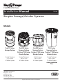
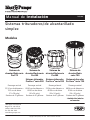
Simplex Sewage/Grinder Systems
Models
Pro370-Series
Sewage System
Pro380-Series
Sewage System
ProVore
®
380-Series
Grinder System
Pro380-Series
Sewage System
ProVore
®
380-Series
Grinder System
700-Series
Sewage System
ProVore
®
700-Series
Grinder System
Vertical Discharge
21”D x 30”H
41 Gallon System
Vertical Discharge
24”D x 24”H
41 Gallon System
Side Discharge
24”D x 24”H
41 Gallon System
Vertical Discharge
24”D x 36”H
70 Gallon System
«Indoor Installation
Only»

– 2 – Copyright © Liberty Pumps, Inc. 2018
All rights reserved. 7225000I
Contents
Safety Precautions . . . . . . . . . . . . . . . . . . . . . . . . . . . . . . . . . . . . . . . . . . . . . . . . . . 3
Introduction . . . . . . . . . . . . . . . . . . . . . . . . . . . . . . . . . . . . . . . . . . . . . . . . . . . . . . . 4
Basin Dimensions . . . . . . . . . . . . . . . . . . . . . . . . . . . . . . . . . . . . . . . . . . . . . . . . . . . 4
Cover Descriptions . . . . . . . . . . . . . . . . . . . . . . . . . . . . . . . . . . . . . . . . . . . . . . . . . . 5
In-Ground Basin Installation . . . . . . . . . . . . . . . . . . . . . . . . . . . . . . . . . . . . . . . . . 6
Installation and Connections . . . . . . . . . . . . . . . . . . . . . . . . . . . . . . . . . . . . . . . . . 6
QuickTree and 370/380-Series Access Cover . . . . . . . . . . . . . . . . . . . . . . . . . . . . . 7
700-Series Access Cover . . . . . . . . . . . . . . . . . . . . . . . . . . . . . . . . . . . . . . . . . . . . . 8
Electrical Service and Operation . . . . . . . . . . . . . . . . . . . . . . . . . . . . . . . . . . . . . . . 8
Supplemental Installation Instructions . . . . . . . . . . . . . . . . . . . . . . . . . . . . . . . . 10
Maintenance and Troubleshooting . . . . . . . . . . . . . . . . . . . . . . . . . . . . . . . . . . . . 11
Warranty . . . . . . . . . . . . . . . . . . . . . . . . . . . . . . . . . . . . . . . . . . . . . . . . . . . . . . . . . 12
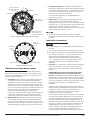
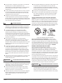
Safety Guidelines
This safety alert symbol is used in the manual and on the pump to alert of potential risk for serious injury
or death.
This safety alert symbol identifies risk of electric shock. It is accompanied with an instruction intended to
minimize potential risk of electric shock.
This safety alert symbol identifies risk of fire. It is accompanied with an instruction intended to minimize
potential risk of fire.
This safety alert symbol identifies risk of serious injury or death. It is accompanied with an instruction
intended to minimize potential risk of injury or death.
Warns of hazards, which if not avoided, will result in serious injury or death.
Warns of hazards, which if not avoided, could result in serious injury or death.
Warns of hazards, which if not avoided, could result in minor or moderate injury.
Signals an important instruction related to the pump. Failure to follow these instructions could result in
pump failure or property damage.
WARNING
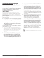
Read every supplied manual before using pump system. Follow all the safety instructions in
manual(s) and on the pump. Failure to do so could result in serious injury or death.
Installer: manual must remain with owner or system operator/maintainer.
Record information from pump nameplate:
Keep this manual handy for future reference.
Pump Model #:
For replacement manual, visit libertypumps.com,
or contact Liberty Pumps at 1-800-543-2550.
Pump Serial #:
Retain dated sales receipt for warranty.
Manufacture Date:
Install Date:
DANGER
WARNING
CAUTION
NOTICE
NOTICE

7225000I Copyright © Liberty Pumps, Inc. 2018
All rights reserved. – 3 –
Safety Precautions
Accidental contact with electrically live parts, items, fluid, or
water can cause serious injury or death.
Always disconnect pump(s) from power source(s) before
handling or making any adjustments to either the pump(s),
the pump system, or the control panel.
All installation and maintenance of pumps, controls,
protection devices, and general wiring shall be done by
qualified personnel.
All electrical and safety practices shall be in accordance with
the National Electrical Code
®
, the Occupational Safety and
Health Administration, or applicable local codes and
ordinances.
Do not remove cord and strain relief, and do not connect
conduit to pump.
Pump shall be properly grounded using its supplied
grounding conductor. Do not bypass grounding wires or
remove ground prong from attachment plugs. Failure to
properly ground the pump system can cause all metal
portions of the pump and its surroundings to become
energized.
Do not handle or unplug the pump with wet hands, when
standing on damp surface, or in water unless wearing
Personal Protective Equipment.
Always wear dielectric rubber boots and other applicable
Personal Protective Equipment (PPE) when water is on the
floor and an energized pump system must be serviced, as
submerged electrical connections can energize the water. Do
not enter the water if the water level is higher than the PPE
protection or if the PPE is not watertight.
Do not lift or carry a pump or a float assembly by its power
cord. This will damage the power cord, and could expose the
electrically live wires inside the power cord.
The electrical power supply shall be located within the length
limitations of the pump power cord, and for below grade
installations, it shall be at least 4
ft (1.22 m) above floor level.
Do not use this product in applications where human contact
with the pumped fluid is common (such as swimming pools,
fountains, marine areas, etc.).
Protect the power and control cords from the environment.
Unprotected power and control (switch) cords can allow
water to wick through ends into pump or switch housings,
causing surroundings to become energized.
Do not use an extension cord to power the product.
Extension cords can overload both the product and extension
cord supply wires. Overloaded wires will get very hot and can
catch on fire.
This product requires a separate, properly fused and
grounded branch circuit, sized for the voltage and amperage
requirements of the pump, as noted on the nameplate.
Overloaded branch circuit wires will get very hot and can
catch on fire.
Do not use this product with or near flammable or explosive
fluids such as gasoline, fuel oil, kerosene, etc. If rotating
elements inside pump strike any foreign object, sparks may
occur. Sparks could ignite flammable liquids.
These pumps are not to be installed in locations classified as
hazardous in accordance with the National Electric Code
®
,
ANSI/NFPA 70.
Sewage and effluent systems produce and may contain
flammable and explosive gases. Prevent introduction of
foreign objects into basin as sparks could ignite these gases.
Use caution using tools and do not use electronic devices or
have live, exposed electrical circuits in or around basins, open
covers and vents.
Do not modify the pump/pump system in any way.
Modifications may affect seals, change the electrical loading
of the pump, or damage the pump and its components.
All pump/pump system installations shall be in compliance
with all applicable Federal, State, and Local codes and
ordinances.
Do not allow children to play with the pump system.
Do not allow any person who is unqualified, to have contact
with this pump system. Any person who is unaware of the
dangers of this pump system, or has not read this manual,
can easily be injured by the pump system.
In 200V/230V installations, one side on the line going to the
pump is always “hot”, whether the float switch is on or off. To
avoid hazards, install a double pole disconnect near the
pump installation.
Vent basin in accordance with local code. Proper venting of
sewer gases alleviates poisonous gas buildup and reduces the
risk of explosion and fire from these flammable gases.
Wear adequate Personal Protective Equipment when working
on pumps or piping that have been exposed to wastewater.
Sump and sewage pumps often handle materials which can
transmit illness or disease upon contact with skin and other
tissues.
Do not enter a pump basin after it has been used. Sewage
and effluent can emit several gases which are poisonous.
Do not remove any tags or labels from the pump or its cord.
Keep clear of suction and discharge openings. To prevent
injury, never insert fingers into pump while it is connected to
a power source.
Do not use this product with flammable, explosive, or
corrosive fluids. Do not use in a flammable and/or explosive
atmosphere as serious injury or death could result.
This product contains chemicals known to the State of
California to cause cancer and birth defects or other
reproductive harm. www.p65warnings.ca.gov.
NOTICE
Do not use pumps with fluid over 140°F (60°C). Operating the
pump in fluid above this temperature can overheat the pump,
resulting in pump failure. Maximum continuous duty fluid
temperature is 104°F (40°C).
WARNING
RISK OF ELECTRIC SHOCK
WARNING
RISK OF FIRE
WARNING
RISK OF SERIOUS INJURY OR DEATH

– 4 – Copyright © Liberty Pumps, Inc. 2018
All rights reserved. 7225000I
Do not use pump system with mud, sand, cement,
hydrocarbons, grease, or chemicals. Pump and system
components can be damaged from these items causing
product malfunction or failure. Additionally, flooding can
occur if these items jam the impeller or piping.
Do not run dry.
The Uniform Plumbing Code
®
states that sewage systems
shall have an audio and visual alarm that signals a
malfunction of the system, to reduce the potential for
property damage.
Do not exert heavy pressure or run heavy equipment on the
backfill material as this could cause the tank to collapse.
Do not overtighten bolts.
Do not position the pump float directly under the inlet from
drain tile or in the direct path of any incoming water.
Side discharge not available for 700-Series basins.
700-Series are not suitable for outdoor applications.
Introduction
Before installation, read the following instructions carefully. Each
pump is individually factory tested to ensure proper performance.
Closely following these instructions will eliminate potential
operating problems, assuring years of trouble-free service.
ProVore
®
grinder systems easily handle solids and sewage
waste found in typical residential applications. Their unique cutter
system grinds difficult wastes and then pumps it through a 1-1/2”
or 2” discharge line. The ProVore 380-Series system is supplied
with a 2” discharge outlet. Do not increase this pipe size above 2”
as adequate flow rates may not be achieved for proper operation.
Discharge sizes may be reduced to 1-1/2” or 1-1/4”. Consult
Liberty Pumps for proper pipe and system sizing.
Pro-Series systems come with an integral control system with
alarm and QuickTree® float system. Pump and alarm floats are
pre-set on the QuickTree system at proper operating levels. The
QuickTree system is located under a separate access cover for
ease of maintenance and service. Floats for both pump activation
and alarm are mounted on a stainless steel tree (rod), separate
from the pump. There is no need to disconnect plumbing or
remove the pump to inspect service or replace floats. QuickTree
floats are preset at the factory for optimum operating levels and
should not be adjusted.
Pro-Series systems also feature a clear disposable construction
cover designed to protect the system during rough-in and
masonry work. The protective cover should remain in place until
finish plumbing; however, it can be removed and reinstalled if
required. The cover is snapped into the threaded ports of the
discharge and vent. To remove the clear cover, simply pull
upward, disengaging it from the discharge and vent holes.
700-Series systems feature a heavy-duty basin with 4” inlet hub
pre-assembled to basin. The system comes pre-assembled from
the factory with pump and automatic controls pre-mounted,
requiring no system assembly at job site. The cover is equipped
with a 2” or 3” discharge and 2” or 3” vent flange. Installation is
limited to indoor only.
Was current system sized by a professional? Minimum fluid flows
are required in sewage applications. Consult Liberty Pumps for
proper pump sizing prior to installation.
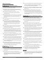
20-¹/ࢩ”
[51.4cm]
3”
[7.6cm]
23”
[58.4cm]
30”
[76.2cm]
10”
[25.4cm]
21-¹/ࢧ”
[54.6cm]
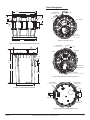
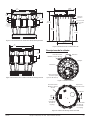
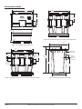
Basin Dimensions
Figure 1. 370-Series Basin Dimensions
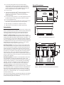
24-³/ࢭ”
[61.9cm]
3-¹/ࢩ”
[7.6cm]
23-¹/ࢧ”
[59.7cm]
25”
[63.5cm]
9-¹/ࢩµ
[23.5cm]
Figure 2. 380-Series Vertical Discharge Basin Dimensions

24-³/ࢭ”
[61.9cm]
7-࢝/ࢭ”
[20cm]
4”
[10.2cm]
3-¹/ࢩ”
[7.6cm]
23-¹/ࢧ”
[59.7cm]
25”
[63.5cm]
9-¹/ࢩ”
[23.5cm]
2” PVC
discharge
Cord exit
2” PVC hub
7225000I Copyright © Liberty Pumps, Inc. 2018
All rights reserved. – 5 –
Figure 3. 380-Series Side Discharge Basin Dimensions
Figure 4. 700-Series Basin Dimensions
Vent
Inlet
Discharge
Nameplate
(model and serial number)
Alarm
(optional, shipped
on top of system)
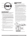
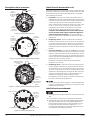
Cover Descriptions
Figure 5. 370-Series Cover
Inlet
Vent
Discharge
Inspection/
Access cover
Nameplate
(model and serial number)
Alarm
(optional, shipped on top of system)
Figure 6. 380-Series Vertical Discharge Cover
Inlet
2” PVC hub
cord exit
Discharge
Inspection/
access cover
Nameplate
(model and serial number)
Figure 7. 380-Series Side Discharge Cover
4” inlet
hub
with 4” seal
Ø30”
[76.2cm]
22-ð/ࢧ”
[57.2cm]
36-ȹ/ࢭ”
[93cm]
41-ò/ࢩ”
[106.1cm]
24
-ȹ/ࢭ
”
[62.5cm]

– 6 – Copyright © Liberty Pumps, Inc. 2018
All rights reserved. 7225000I
Figure 8. 700-Series Cover
In-Ground Basin Installation
ProVore and Pro-Series basins can be installed in both indoor and
outdoor applications. The 700-Series basins are not suitable for
outdoor applications and can only be installed indoors.
A. Excavation: Excavate the hole as small as possible, with a
minimum
recommended 8” diametrical clearance around the
tank. Never place the basin directly in contact with rocks or
other sharp objects. Place only fine, 1/8” to 3/4” pea gravel or
1/8” to 1/2” washed, crushed stone as bedding between the
basin and the hole walls. Do not use sand or native soil as
backfill. Properly compact underneath the basin to provide
a solid, level base that can support the weight of the filled
basin. It is recommended that the top lip of the basin be level
with the finished floor.
B. Initial Backfill: Only fine, 1/8” to 3/4” pea gravel or 1/8” to
1/2” washed, crushed stone should be used around the
bottom of the basin to hold it in place. Do not use sand or
native soil as backfill. Make the inlet connection as required
for particular basin.
C. Inlet Connection: Pr
o-Series basins have a 4” inlet molded
to the side of the tank. This inlet is sized to accept a 4”
no-hub type coupling. 700-Series basins use a hub with a 4”
seal for inlet connection.
Connect the gravity drainage line from the fixtures to this
hub.
D. Final Backfill: Large rocks, clods, and foreign objects should
be
kept out of the backfill material. Only fine, 1/4” to 3/4” pea
gravel, or 1/8” to 1/2” washed, crushed stone is
recommended. Do not use sand or native soil as backfill.
Mound the backfill slightly and allow for natural settling.
Provide access to the basin cover for maintenance and
service.
NOTICE
Do not exert heavy pressure or run heavy equipment on the
backfill material as this could cause the tank to collapse.
Installation and Connections
NOTICE
Side discharge not available for 700-Series basins.
700-Series are not suitable for outdoor applications.
Do not increase 702/PRG system discharge pipe size
above 2” as adequate flow rates may not be achieved for
proper operation. Discharge sizes may be reduced to 1-1/4”.
Contact Liberty Pumps with questions regarding proper pipe
sizes and flow rates.
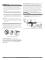
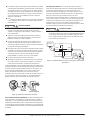
E. Discharge: Using an adapter, connect the discharge pipe to
the threaded 2” or 3” port provided on the cover (or the 2”
PV
C nipple used on side discharge models).
IMPORTANT: Do not reduce the discharge pipe size below
that which is provided on the pump. Sewage pumps
discharge size should not be smaller than 2”. In some
applications, it may be necessary to increase the pipe size to
reduce friction losses. Contact Liberty Pumps with questions
regarding proper pipe sizes and flow rates.
Install the remaining discharge line. In vertical discharge
applications,
a union should be installed just above the cover
to facilitate pump removal if necessary (side discharge
applications are equipped with an in-basin union).
In both vertical and side discharge models, a check valve is
recommended after the union to prevent the backflow of
liquid after each pumping cycle. A gate or ball valve should
follow
the check valve to allow periodic cleaning of the check
valve or removal of the pump. The remainder of the discharge
line should be as short as possible with a minimum number
of turns, to minimize friction head loss. Do not restrict the
discharge below 2” in sewage applications. Larger pipe sizes
may be required to eliminate friction head loss over long
runs. Contact Liberty Pumps or other qualified person if there
are questions regarding proper pipe size and flow rates.
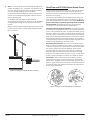
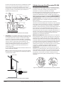
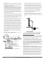
Figure 9 shows a typical outdoor installation. Variations may
apply to actual installation.
Alarm
(optional)
Vent
Union Check Valve
Ball Valve
Discharge
Use No-hub Style
Connector 4" Inlet Pipe
Figure 9. Typical Installation (Pro380-Series shown)
Discharge
Vent
Cord entry
Access cover
Nameplate

7225000I Copyright © Liberty Pumps, Inc. 2018
All rights reserved. – 7 –
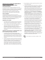
F. Vent: On Pro370, 700, and vertical discharge Pro380-Series
models, a threaded 2” or 3” connection is provided on top of
the cover. The vent must be piped to the existing building
vent, or extended outside on its own standpipe.
On both side and vertical discharge systems, the vent size
must be in accordance with applicable codes, but not less
than the discharge size.
On Pro380SD (side discharge) models, venting is
accomplished through the inlet. See Figure 10 for Pro380SD
venting example through the inlet pipe as an alternative
solution.
SYSTEM
VENT
DISCHARGE
WATER
CLOSET
VENT
Note: Pro-Series systems shipped with steel pipe option have
a rubber grommet seal on the discharge instead of female
NPT connections.
Figure 10. Example Pro380SD Alternative Venting
QuickTree and 370/380-Series Access Cover
Liberty Pumps Pro370 systems and vertical discharge 380-Series
systems feature QuickTree technology. Floats for both pump
activation and alarm (if equipped) are mounted on the QuickTree,
separate from the pump.
The QuickTree float system uses a stainless steel mounting rod
(tree) and specially designed cord clamping brackets to affix the
pump
float and (optional) alarm float in the system. All floats are
preset at the factory at optimum operating levels and should
not be adjusted. Field adjusting floats may cause improper
activation or turn-off of the pump and optional alarm.
QuickTree removal and float inspection: The QuickTree system
is
located under the separate access cover to help ease inspection,
service, and replacement of a float. To inspect the float(s), simply
unbolt the access cover and lift out the QuickTree assembly from
its holder. There is no need to disconnect plumbing or remove the
pump. Vertical discharge systems feature a manual pump (with no
switch attached directly to the pump). Operation of the pump is
accomplished by the QuickTree system. Side discharge 380-Series
systems are equipped with an automatic pump.
Re-inserting the QuickTree: After service or inspection of the
floats, re-insert the QuickTree into its holder. It is important that
cords
from the pump motor, float switch, and optional alarm float
are properly sealed in the specially designed rubber sealing
channels under the access cover. Proper sealing is required to
keep sewer gas from leaking from the system. Place the cords
securely in the rubber channels as shown in Figure 11 [left], being
careful to remove excessive cord “slack” from inside the system.
IMPORTANT: Three cord channels are provided. For systems
without the alarm option, only two channels are used and the
third must be “plugged” with an attached rubber plug seal. See
Figure 11 [right]. If the alarm cord is present, all three channels will
be used. All rubber cover gaskets are permanently attached and
do not require replacement.
RUBBER
PLUG SEAL
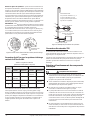
Figure 11. Proper Cord Sealing Behind QuickTree Rod

– 8 – Copyright © Liberty Pumps, Inc. 2018
All rights reserved. 7225000I
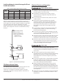
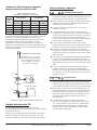
QuickTree Settings for Vertical Discharge Pro370 and
Pro380-Series Systems
Table 1. Tether Length (Switch Position to Clamp)
Pro370-Series Pro380-Series
Alarm Float Control Float Alarm Float Control Float
When servicing the QuickTree, place the switch cord into the
trough or channel and then slip the stainless steel rod through the
clamp. Tighten the screw with a Phillips screwdriver, being careful
not to overtighten. Flats have been stamped on the rod to
designate float position, and the screw should be tightened onto
the flat. Tether length is the amount of cord between the clamp
and float.
P370-SERIES SHOWN
Float positions 1, 2, 3,
and 4 are identified by
flats stamped onto the
stainless rod. 1 is
highest; 4 is lowest.
ALARM FLOAT
PUMP CONTROL FLOAT
TETHER LENGTH
1
2
4
3
(ON OPPOSITE SIDE)
Figure 12. QuickTree Example Settings
700-Series Access Cover
The 700-Series cover contains access to the float and alarm cord
entry/exit seals. Refer to Figure 8 for these locations.
QuickTree is not available on 700-Series systems. The pump
control float is attached to the pump while the alarm float is on
the discharge pipe.
Electrical Service and Operation
Always disconnect pump(s) from power source(s) before
handling or making any adjustments to either the pump(s),
the pump system, or the control panel.
All installation and maintenance of pumps, controls,
protection devices, and general wiring shall be done by
qualified personnel.
Do not remove cord and strain relief, and do not connect
conduit to pump.
Pump shall be properly grounded using its supplied
grounding conductor. Do not bypass grounding wires or
remove ground prong from attachment plugs. Failure to
properly ground the pump system can cause all metal
portions of the pump and its surroundings to become
energized.
Do not handle or unplug the pump with wet hands, when
standing on damp surface, or in water unless wearing
Personal Protective Equipment.
Do not lift or carry a pump or a float assembly by its power
cord. This will damage the power cord, and could expose the
electrically live wires inside the power cord.
The
electrical power supply shall be located within the length
limitations of the pump power cord, and for below grade
installations, it shall be at least 4 ft (1.22 m) above floor level.
Protect the power and control cords from the environment.
Unprotected power and control (switch) cords can allow
water to wick through ends into pump or switch housings,
causing surroundings to become energized.
Do not use an extension cord to power the product.
Extension
cords can overload both the product and extension
cord supply wires. Overloaded wires will get very hot and can
catch on fire.
This product requires a separate, properly fused and
grounded branch circuit, sized for the voltage and amperage
requirements of the pump, as noted on the nameplate.
Overloaded branch circuit wires will get very hot and can
catch on fire.
Do not use this product with or near flammable or explosive
fluids such as gasoline, fuel oil, kerosene, etc. If rotating
elements inside pump strike any foreign object, sparks may
occur. Sparks could ignite flammable liquids.
Sewage and effluent systems produce and may contain
flammable and explosive gases. Prevent introduction of
foreign objects into basin as sparks could ignite these gases.
Use caution using tools and do not use electronic devices or
have
live, exposed electrical circuits in or around basins, open
covers and vents.
These pumps are not to be installed in locations classified as
hazardous in accordance with the National Electric Code
®
,
ANSI/NFPA 70.
Rod
P
osition
1 3.5”
2 3.5”
3 3.0”
4
3.5”
WARNING
RISK OF ELECTRIC SHOCK
WARNING
RISK OF FIRE

7225000I Copyright © Liberty Pumps, Inc. 2018
All rights reserved. – 9 –
Do not modify the pump/pump system in any way.
Modifications may affect seals, change the electrical loading
of the pump, or damage the pump and its components.
All pump/pump system installations shall be in compliance
with all applicable Federal, State, and Local codes and
ordinances.
Vent basin in accordance with local code. Proper venting of
sewer
gases alleviates poisonous gas buildup and reduces the
risk of explosion and fire from these flammable gases.
Wear
adequate Personal Protective Equipment when working
on pumps or piping that have been exposed to wastewater.
Sump and sewage pumps often handle materials which can
transmit illness or disease upon contact with skin and other
tissues.
Do not remove any tags or labels from the pump or its cord.
Keep clear of suction and discharge openings. To prevent
injury, never insert fingers into pump while it is connected to
a power source.
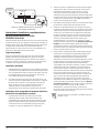
All Pro370 and vertical discharge Pro380-Series models come
factory-equipped
with the float switch mounted on the QuickTree
assembly. These models come with two cords—one to the float
switch and the other to the pump motor. The switch cord has a
series (piggyback) plug enabling the pump (motor) cord to be
plugged into the back of it (Figure 13). The purpose of this design
is to allow manual operation of the pump.
Temporary Manual
Operation
YES!NO!
Figure 13. Piggyback Plug Installation
For automatic operation, the two cords should be
interconnected and plugged into a separately fused, grounded
outlet of proper amp capacity for the selected pump model. Both
cords
are equipped with 3-prong plugs and must be plugged into
a properly grounded 3-wire receptacle. Do not remove the
ground prongs.
For manual operation,
or in the event of switch failure, the pump
cord can be separated and plugged into the electrical outlet
directly, bypassing the switch. 200V/230V single-phase pumps
should only be operated without the float switch by using the
circuit breaker or panel disconnect. Do not let the pump run dry.
If the pump will be wired directly into a control device or junction
box, and it is necessary to remove the plugs, have a certified
electrician do the wiring in accordance with the National Electric
Code and applicable local codes. See Figure 14 for typical direct
wire installation of single-phase, automatic pumps.
In 200V/230V installations, one side on the line going to the
pump is always “hot”, whether the float switch is on or off. To
avoid hazards, install a double pole disconnect near the
pump installation.
Ground
Black
Junction Box
Power
Supply
Float
Switch
Pump
Green
Black
White
Green
Black
White
White
Figure 14. Direct Wiring of 115V or 200V/230V, 1PH, Auto Pumps
WARNING
RISK OF SERIOUS INJURY OR DEATH
WARNING
RISK OF SERIOUS INJURY OR DEATH

– 10 – Copyright © Liberty Pumps, Inc. 2018
All rights reserved. 7225000I
Supplemental Installation Instructions
PRO370XL/PRO380XL-Series 10' Stack Test Basins
XL-Series sewage ejector basins are designed to withstand the 10'
stack test required by some municipalities. Proper installation of
the specified cover flange is essential to ensure that the test is
met. Strict adherence to these instructions is required. Under no
circumstances should the cover be installed in a manner
inconsistent with these instructions.
Types of Systems
XL-Series basins are available as fully assembled systems
complete with pump and discharge piping, as basin and cover
assembly kits with no pump or plumbing, and as basins only.
Follow the instructions below, as applicable, to correspond to the
specific type of system.
Basin Installation
1. For all systems, refer to the primary instructions supplied with
this ejector system or basin for excavating the pit, plumbing
connections, and backfilling.
2. If the top of the basin is below grade, an access riser (model
ARC18) is required. The maximum burial depth is 18” with
respect to the top of the basin. Consult Liberty Pumps at
1-800-543-2550 or a local distributor for more information
on ARC Series Access Risers.
Installing the Pump in the XL-Series Basin or XL Basin
and Cover Assembly Kit
1. Liberty Pumps XL-Series basins, purchased separately, will
require the appropriate 16-bolt Pro-Series cover assembly to
make an effectively sealed ejector system. Contact Liberty
Pumps customer service for the proper cover for the
application.
2. Size the length of the discharge piping to reach from the
discharge of the pump to be within the discharge pipe socket
with integral lip seal on the underside of the Pro-Series cover.
Liberty Pumps sewage pumps will use threaded-one-end
(TOE) nipples of 23.75” length for Pro370XL-Series Basins, or
17.50” long for Pro380XL-Series Basins. Install the pipe into
the threaded discharge of the pump.
3. Lower the pump into the basin, fitting the pump legs into the
torque stops.
4. Insert power cord for the pump—and the piggyback switch
cord, if so equipped—through the underside of the
inspection cover hole and position cover over pipe nipple
while aligning the bolt holes. Sealant (such as silicone) can be
applied on both sides of the rubber gasket surface to ensure
proper sealing. Use sixteen 1/4-20 UNC bolts and washers to
secure cover to the basin. Tighten bolts to 40 inch-pounds.
Do not overtighten bolts. The soft, integral gasket will
conform to the top of the tank. The bolts may be re-torqued
up to 60 inch-pounds to seal any leaks that may occur during
a 10' stack test.
5. Liberty Pumps recommends the use of manual type pumps
and the appropriate Liberty Pumps QuickTree Switch Kit for
mounting of pump control and alarm floats. Contact
customer service for ordering information. Install the
QuickTree Kit per instructions included. Liberty Pumps
automatic type pumps with piggyback float switches may also
be used. Lay the power cable and switch cable in the grooves
in the inspection cover recess as shown in the primary
instructions included with this system. Attach the inspection
cover to the main cover using supplied bolts and washers.
Sealant (such as silicone) can be applied on both sides of the
rubber gasket surface to ensure proper sealing. Tighten the
bolts furthest away from the power cord grooves first,
torquing to 40 inch-pounds. Do not overtighten bolts. The
soft, integral gasket will conform to the top of the cover and
power cords. The bolts may be re-torqued up to 60
inch-pounds to seal any leaks that may occur during a 10'
stack test.
Pro370XL and Pro380XL Series Basins IAPMO listed, # 4361

7225000I Copyright © Liberty Pumps, Inc. 2018
All rights reserved. – 11 –
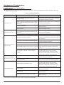
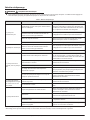
Maintenance and Troubleshooting
Always disconnect pump(s) from power source(s) before handling or making any adjustments to either the pump(s), the pump
system, or the control panel.
WARNING
RISK OF ELECTRIC SHOCK
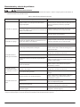
Table 2. Troubleshooting Matrix
Problem Possible Cause Corrective Action
Pump will not run.
Blown fuse or other interruption of power;
improper voltage.
Check that the unit is securely plugged in. Have an
electrician check all wiring for proper connections
and adequate voltage and capacity.
Switch is unable to move to the “turn on” position
due to interference with the side of basin or other
obstruction.
Position the pump or switch so that it has adequate
clearance for free operation.
Insufficient liquid level.
Verify the liquid level is allowed to rise enough to
activate switch(es).
Defective switch. Remove and replace switch.
Pump will not turn off.
Switch unable to move to the “turn off” position
due to interference with the side of basin or other
obstruction.
Position the pump or switch so that it has adequate
clearance for free operation.
Defective switch. Remove and replace switch.
Pump runs or hums, but
does not pump.
Discharge is blocked or restricted.
Check the discharge line for foreign material,
including ice if the discharge line passes through or
into cold areas.
Check valve is stuck closed or installed backwards.
Remove check valve and examine for freedom of
operation and proper installation.
Gate or ball valve is closed. Open gate or ball valve.
Total head (lift height) is beyond pump's capability.
Try to route piping to a lower level. If not possible,
a larger pump may be required. Consult Liberty
Pumps.
Pump impeller is jammed or volute casing is
plugged.
Remove the pump from the basin. Remove cutter
and cutter plate. Clean the area around the
impeller. Reassemble and reinstall. The center
screw uses a 6 mm hex drive. The screw can be
heated to remove thread locking compound.
Pump runs periodically
when fixtures are not in use.
Check valve was not installed, is stuck open, or is
leaking.
Remove check valve and examine for freedom of
operation and proper installation.
Fixtures are leaking. Repair fixtures as required to eliminate leakage.
Pump operates noisily.
Foreign objects in the impeller cavity.
Remove the pump from the basin. Remove cutter
and cutter plate. Clean the area around the
impeller. Reassemble and reinstall. The center
screw uses a 6 mm hex drive. The screw can be
heated to remove thread locking compound.
Broken impeller.
Consult Liberty Pumps for information regarding
replacement of impeller.
Worn bearings.
Return pump to Liberty Pumps or authorized repair
station for repair.
Piping attachments to building are too rigid.
Replace a portion of the discharge line with rubber
hose or connector.
NOTE: Liberty Pumps, Inc. assumes no responsibility for damage or injury due to disassembly in the field. Disassembly, other than at
Liberty Pumps or its authorized service centers, automatically voids warranty.

– 12 – Copyright © Liberty Pumps, Inc. 2018
All rights reserved. 7225000I
Warranty
Liberty Pumps Wholesale Products Limited Warranty
Liberty Pumps, Inc. warrants that Liberty Pumps wholesale products are free from all factory defects in material and workmanship for a
period of three (3) years from the date of purchase (excluding batteries). The date of purchase shall be determined by a dated sales
receipt noting the model and serial number of the pump. The dated sales receipt must accompany the returned pump if the date of
return is more than three years from the date of manufacture noted on the pump nameplate.
The manufacturer's sole obligation under this Warranty shall be limited to the repair or replacement of any parts found by the
manufacturer to be defective, provided the part or assembly is returned freight prepaid to the manufacturer or its authorized service
center, and provided that none of the following warranty-voiding characteristics are evident:
The manufacturer shall not be liable under this Warranty if the product has not been properly installed, operated, or maintained per
manufacturer instructions; if it has been disassembled, modified, abused, or tampered with; if the electrical cord has been cut, damaged,
or spliced; if the pump discharge has been reduced in size; if the pump has been used in water temperatures above the advertised rating;
if the pump has been used in water containing sand, lime, cement, gravel, or other abrasives; if the product has been used to pump
chemicals, grease, or hydrocarbons; if a non-submersible motor has been subjected to moisture; or if the label bearing the model and
serial number has been removed.
Liberty Pumps, Inc. shall not be liable for any loss, damage, or expenses resulting from installation or use of its products, or for indirect,
incidental, and consequential damages, including costs of removal, reinstallation or transportation.
There is no other express warranty. All implied warranties, including those of merchantability and fitness for a particular purpose, are
limited to three years from the date of purchase. This Warranty contains the exclusive remedy of the purchaser, and, where
permitted, liability for consequential or incidental damages under any and all warranties are excluded.
7000 Apple Tree Avenue
Bergen, NY 14416
ph: 800-543-2550
fax: 585-494-1839
www.libertypumps.com

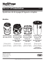
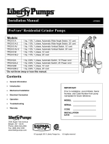
Manual de Instalación
7000 Apple Tree Avenue
Bergen, NY 14416 EUA
teléfono: 800-543-2550
fax: 585-494-1839
www.libertypumps.com
Copyright © Liberty Pumps, Inc. 2018
Todos los derechos reservados.
7225000I
PUMPS
Sistemas trituradores/de alcantarillado
simplex
Modelos
Sistema de
alcantarillado serie
Pro370
Sistema de
alcantarillado serie
Pro380
Sistema triturador
ProVore
®
serie 380
Sistema de
alcantarillado serie
Pro380
Sistema triturador
ProVore
®
serie 380
Sistema de
alcantarillado
serie 700
Sistema triturador
ProVore
®
serie 700
Descarga vertical
53.34 cm de diámetro x
76.2 cm de altura
(21 x 30 pulg.)
Sistema de 41 galones
Descarga vertical
60.96 cm de diámetro x
60.96 cm de altura
(24 x 24 pulg.)
Sistema de 41 galones
Descarga lateral
53.34 cm de diámetro x
60.96 cm de altura
(24 x 24 pulg.)
Sistema de 41 galones
Descarga vertical
60.96 cm de diámetro x
91.44 cm de altura
(24 x 36 pulg.)
Sistema de 70 galones
«Instalación interior
solamente»

– 2 – Copyright © Liberty Pumps, Inc. 2018
Todos los derechos reservados. 7225000I
Contenido
Medidas de seguridad . . . . . . . . . . . . . . . . . . . . . . . . . . . . . . . . . . . . . . . . . . . . . . . 3
Introducción . . . . . . . . . . . . . . . . . . . . . . . . . . . . . . . . . . . . . . . . . . . . . . . . . . . . . . . 4
Dimensiones de la cuenca . . . . . . . . . . . . . . . . . . . . . . . . . . . . . . . . . . . . . . . . . . . . 4
Descripciones de la cubierta . . . . . . . . . . . . . . . . . . . . . . . . . . . . . . . . . . . . . . . . . . 5
Instalación en el suelo de las cubetas . . . . . . . . . . . . . . . . . . . . . . . . . . . . . . . . . . 6
Instalación y conexiones . . . . . . . . . . . . . . . . . . . . . . . . . . . . . . . . . . . . . . . . . . . . . 6
Cubierta de acceso QuickTree series 370/380 . . . . . . . . . . . . . . . . . . . . . . . . . . . . 7
Cubierta de acceso serie 700 . . . . . . . . . . . . . . . . . . . . . . . . . . . . . . . . . . . . . . . . . . 8
Servicio eléctrico y operación . . . . . . . . . . . . . . . . . . . . . . . . . . . . . . . . . . . . . . . . . 8
Instrucciones de instalación suplementarias . . . . . . . . . . . . . . . . . . . . . . . . . . . 10
Mantenimiento y solución de problemas . . . . . . . . . . . . . . . . . . . . . . . . . . . . . . . 11
Garantía . . . . . . . . . . . . . . . . . . . . . . . . . . . . . . . . . . . . . . . . . . . . . . . . . . . . . . . . . 12
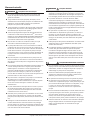
Reglas de seguridad
Este símbolo de alerta de seguridad se usa en el manual y en la bomba para alertar sobre el riesgo
potencial de lesiones graves o la muerte.
Este símbolo de alerta de seguridad identifica el riesgo de descarga eléctrica. Se acompaña con una
instrucción destinada a minimizar el riesgo potencial de descarga eléctrica.
Este símbolo de alerta de seguridad identifica el riesgo de incendio. Se acompaña con una instrucción
destinada a minimizar el riesgo potencial de incendio.
Este símbolo de alerta de seguridad identifica el riesgo de lesiones graves o la muerte. Se acompaña con
una instrucción destinada a minimizar el riesgo potencial de lesión o muerte.
Advierte sobre peligros que, si no se evitan, provocarán lesiones graves o la muerte.
Advierte sobre los peligros que, si no se evitan, pueden provocar lesiones graves o la muerte.
Advierte sobre peligros que, si no se evitan, pueden ocasionar lesiones leves o moderadas.
Señala una instrucción importante relacionada con la bomba. El incumplimiento de estas instrucciones
puede ocasionar fallas en la bomba o daños a la propiedad.
Lea todos los manuales suministrados antes de usar el sistema de bomba. Siga todas las
instrucciones de seguridad de los manuales y de la bomba. De lo contrario, podrían producirse
lesiones graves o la muerte.
Instalador: el manual debe permanecer con el propietario o el operador/encargado del
sistema.
Registre la información de la placa de identificación de la bomba:
Mantenga este manual a mano para futuras
referencias.
N.° de modelo de la bomba:
Para obtener un manual de reemplazo, visite
libertypumps.com, o comuníquese con Liberty
Pumps al 1-800-543-2550. N.° de serie de la bomba:
Conserve el recibo de venta fechado para la
garantía. Fecha de fabricación:
Fecha de instalación:
PELIGRO
ADVERTENCIA
ATENCIÓN
AVISO
ADVERTENCIA
AVISO

7225000I Copyright © Liberty Pumps, Inc. 2018
Todos los derechos reservados. – 3 –
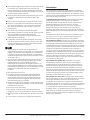
Medidas de seguridad
El contacto accidental con partes, elementos, fluido o agua
bajo tensión puede causar lesiones graves o la muerte.
Desconecte siempre las bombas de las fuentes de
alimentación antes de manipular o realizar cualquier ajuste en
las bombas, el sistema de bomba o el panel de control.
Toda la instalación y el mantenimiento de bombas, controles,
dispositivos de protección y cableado general deben ser
realizados por personal calificado.
Todas las prácticas eléctricas y de seguridad deben realizarse
según el National Electrical Code
®
, la Administración de
Seguridad y Salud Ocupacional, o los códigos y las
ordenanzas locales aplicables.
No quite el cable y el alivio de tensión, y no conecte el
conducto a la bomba.
La bomba debe estar correctamente conectada a tierra
utilizando el conductor de conexión a tierra suministrado. No
puentee los cables de conexión a tierra ni quite la conexión a
tierra de los enchufes. Si el sistema de la bomba no se
conecta a tierra correctamente, se pueden energizar todas las
partes metálicas de la bomba y sus alrededores.
No manipule ni desenchufe la bomba con las manos
mojadas, mientras esté de pie sobre una superficie húmeda o
en agua, a menos que use el equipo de protección personal.
Siempre use botas de goma dieléctrica y otros equipos de
protección personal (EPP) aplicables cuando haya agua en el
piso y se deba revisar un sistema de bomba energizado, ya
que las conexiones eléctricas sumergidas pueden energizar el
agua. No ingrese en el agua si el nivel es más alto que la
protección del EPP o si el equipo no es hermético.
No levante ni transporte una bomba o un conjunto de
flotador por el lado del cable de alimentación. Esto dañará el
cable de alimentación y podría exponer los hilos bajo tensión
dentro del cable.
El suministro de energía eléctrica se debe ubicar dentro de las
limitaciones de longitud del cable de alimentación de la
bomba, y para las instalaciones por debajo del nivel del suelo,
debe ser de al menos 4
pies (1.22 m) por encima del nivel del
suelo.
No utilice este producto en aplicaciones donde el contacto
humano con el fluido bombeado sea común (como piscinas,
fuentes, áreas marinas, etc.).
Proteja el cable de alimentación del medio ambiente. Los
cables de alimentación y de interruptor desprotegidos
pueden permitir que el agua se filtre a través de los extremos
en la bomba o en la carcasa del interruptor y, de esta forma,
energizar el entorno.
No use un cable de extensión para alimentar el producto. Los
cables de extensión pueden sobrecargar tanto el producto
como los hilos de suministro del cable de extensión. Los hilos
sobrecargados se pueden calentar mucho y prenderse fuego.
Este producto requiere un circuito derivado separado, con
fusibles adecuados y conectado a tierra, dimensionado para
los requisitos de voltaje y amperaje de la bomba, como se
indica en la placa de identificación. Los cables de circuitos
derivados sobrecargados se pueden calentar mucho y
prenderse fuego.
No utilice este producto con líquidos inflamables o
explosivos como gasolina, aceite combustible, queroseno,
etc., como así tampoco en sus cercanías. Si los elementos
giratorios dentro de la bomba golpean cualquier objeto
extraño, pueden producirse chispas. Las chispas podrían
encender líquidos inflamables.
Estas bombas no deben instalarse en ubicaciones clasificadas
como peligrosas de acuerdo con el National Electric Code
®
,
ANSI/NFPA 70.
Los sistemas de alcantarillado y efluentes producen y pueden
contener gases inflamables y explosivos. Evite la introducción
de objetos extraños en la cubeta ya que las chispas podrían
encender estos gases. Tenga cuidado al usar herramientas y
no use dispositivos electrónicos o tenga circuitos eléctricos
vivos y expuestos en o alrededor de cuencas, cubiertas
abiertas y respiraderos.
No modifique el sistema de bomba/la bomba de ninguna
manera. Las modificaciones pueden afectar los sellos,
cambiar la carga eléctrica de la bomba, o dañar la bomba y
sus componentes.
Todas las instalaciones del sistema de bomba/la bomba
deberán cumplir con todos los códigos y las ordenanzas
federales, estatales y locales aplicables.
No permita que los niños jueguen con el sistema de bomba.
No permita que ninguna persona no calificada tenga
contacto con este sistema de bomba. Cualquier persona que
no tenga conocimiento de los peligros de este sistema de
bomba o que no haya leído este manual, puede resultar
fácilmente lesionada.
En las instalaciones de 200V/230V, un lado de la línea que va
a la bomba siempre está “caliente”, independientemente de si
el interruptor de flotador está encendido o apagado. Para
evitar riesgos, instale una desconexión de doble polo cerca
de la instalación de la bomba.
Cuenca de ventilación de acuerdo con el código local. La
ventilación adecuada de los gases de alcantarilla alivia la
acumulación de gas venenoso y reduce el riesgo de explosión
y fuego de estos gases inflamables.
Use equipo de protección personal adecuado cuando trabaje
en bombas o tuberías que hayan estado expuestas a aguas
residuales. Las bombas de sumidero y de aguas residuales a
menudo manipulan materiales que pueden transmitir
enfermedades al contacto con la piel y otros tejidos.
No ingrese en un tanque de bombeo después de que se ha
utilizado. Las aguas residuales y los efluentes pueden emitir
varios gases venenosos.
No quite etiquetas de la bomba ni del cable.
Manténgase alejado de las aberturas de succión y descarga.
Para evitar lesiones, nunca inserte los dedos en la bomba
mientras está conectada a una fuente de alimentación.
ADVERTENCIA
RIESGO DE SHOCK ELÉCTRICO
ADVERTENCIA
RIESGO DE FUEGO
ADVERTENCIA
RIESGO DE MUERTE

– 4 – Copyright © Liberty Pumps, Inc. 2018
Todos los derechos reservados. 7225000I
No use este producto con fluidos inflamables, explosivos o
corrosivos. No lo use en una atmósfera inflamable o
explosiva, ya que podría ocasionar lesiones graves o la
muerte.
Este producto contiene productos químicos que el estado de
California sabe que causan cáncer, defectos de nacimiento u
otros daños reproductivos. www.p65warnings.ca.gov.
AVISO
No utilice estas bombas con líquido a más de 140°F (60°C). Si
lo hiciera, puede sobrecalentar la bomba y provocar una falla.
La temperatura máxima del líquido en funcionamiento
continuo es de 104°F (40°C).
No utilice el sistema de bomba con lodo, arena, cemento,
hidrocarburos, grasa o productos químicos. Los componentes
de la bomba y del sistema podrían dañarse, y provocar un
mal funcionamiento o una falla del producto. Además, puede
producirse una inundación si estos materiales atascan el
impulsor o la tubería.
No utilice el sistema en seco.
El Código uniforme de plomería (Uniform Plumbing Code®)
establece que los sistemas de desagüe deben tener una
alarma auditiva y visual que indique un mal funcionamiento
del sistema para reducir el riesgo de daños materiales.
No ejerza una presión excesiva ni trabaje con equipos
pesados sobre el material de relleno, ya que podría colapsar
el tanque.
No apriete demasiado los pernos.
No coloque el flotador de la bomba directamente debajo del
punto de admisión del tubo de desagüe o en el recorrido
directo del agua entrante.
La descarga lateral no está disponible para los lavabos de la
serie 700.
La serie 700 no es adecuada para aplicaciones al aire libre.
Introducción
Antes de la instalación, lea atentamente las siguientes
instrucciones. Cada bomba se prueba individualmente en fábrica
para garantizar un rendimiento adecuado. Si se respetan estas
instrucciones, se evitarán posibles problemas operativos y se
asegurará años de funcionamiento sin problemas.
Los sistemas trituradores ProVore
® se encargan fácilmente de
sólidos y desechos de aguas residuales que se encuentran en
aplicaciones residenciales típicas. Su exclusivo sistema de corte
tritura desechos difíciles y luego los bombea a través de una línea
de descarga de 1-1/2” o 2”. El sistema ProVore serie 380 se
suministra con una salida de descarga de 2”. No aumente este
tamaño de tubería por encima de 2” ya que es posible que no se
logren tasas de flujo adecuadas para una operación adecuada.
Los tamaños de descarga pueden reducirse a 1-1/2” o 1-1/4”.
Consulte a Liberty Pumps para conocer el tamaño correcto de la
tubería y del sistema.
Los sistemas Pro-Series incluyen un sistema de control integral
con alarma y QuickTree®. Los flotadores de la bomba y de la
alarma
están preconfigurados en el sistema QuickTree a niveles de
funcionamiento adecuados. No ajuste los flotadores. El sistema
QuickTree está ubicado debajo de una cubierta de acceso
independiente para facilitar el mantenimiento y el servicio. Los
flotadores para la activación de la bomba y la alarma están
montados en un árbol de acero inoxidable (varilla), separados de
la bomba. No es necesario desconectar la tubería ni retirar la
bomba para inspeccionar el servicio o reemplazar los flotadores.
Los flotadores QuickTree vienen preconfigurados de fábrica para
obtener niveles operativos óptimos y no deben ajustarse.
Los sistemas Pro-Series también cuentan con una cubierta de
construcción
desechable y transparente diseñada para proteger el
sistema durante el trabajo preliminar y de albañilería. La cubierta
protectora debe permanecer en su lugar hasta terminar la
plomería; sin embargo, se puede quitar y reinstalar si es necesario.
La cubierta se encaja en los puertos roscados de la descarga y la
ventilación. Para quitar la cubierta transparente, simplemente tire
hacia arriba desenganchándola de los orificios de descarga y
ventilación.
Los sistemas de la serie 700
cuentan con un lavabo para servicio
pesado con un cubo de entrada de 4” preensamblado en el
lavabo. El sistema viene preensamblado de fábrica con la bomba y
los controles automáticos premontados, lo que no requiere
ensamblaje del sistema en el sitio de trabajo. La cubierta está
equipada con una descarga de 2” o 3” y una brida de ventilación
de 2” o 3”. La instalación está limitada solo en interiores.
¿El sistema actual fue medido por un profesional? Se requieren
flujos mínimos de fluido en aplicaciones de alcantarillado.
Consulte a Liberty Pumps para conocer el tamaño correcto de la
bomba antes de la instalación.
20-¹/ࢩ”
[51.4cm]
3”
[7.6cm]
23”
[58.4cm]
30”
[76.2cm]
10”
[25.4cm]
21-¹/ࢧ”
[54.6cm]
Dimensiones de la cuenca
Figura 1. Dimensiones de la cubeta serie 370

24-³/ࢭ"
[61.9cm]
7-࢝/ࢭ"
[20cm]
4"
[10.2cm]
3-¹/ࢩ"
[7.6cm]
23-¹/ࢧ"
[59.7cm]
25"
[63.5cm]
9-¹/ࢩ"
[23.5cm]
Juntas de
desagüe de
pvc de 5.08 cm
(2 pulg.)
Boca de salida
del cable de
pvc de 5.08 cm
(2 pulg.)
7225000I Copyright © Liberty Pumps, Inc. 2018
Todos los derechos reservados. – 5 –
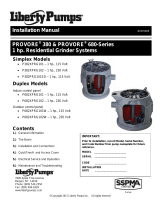
Figura 2. Dimensiones de la cubeta serie 380 de descarga lateral
Figura 3. Dimensiones de la cubeta serie 380 de descarga vertical
Figura 4. Dimensiones de la cubeta serie 700
Ventilación
Placa del nombre
Modelo y numero de serie
Admisión
Desagüe
Alarma (opcional,
viene en la parte
superior del sistema)
Descripciones de la cubierta
Figura 5. Cubierta serie 370
Figura 6. Cubierta de descarga lateral serie 380
24-³/ࢭ”
[61.9cm]
3-¹/ࢩ”
[7.6cm]
23-¹/ࢧ”
[59.7cm]
25”
[63.5cm]
9-¹/ࢩµ
[23.5cm]
Tubo de entrada
de 4 "con sello
de 4"
Tanque de
polietileno
Ø30"
[76.2cm]
22-ð/ࢧ"
[57.2cm]
36-ȹ/ࢭ"
[93cm]
24
-ȹ/ࢭ
"
[62.5cm]
41-ò/ࢩ"
[106.1cm]
Admisión
Desagüe:
Junta de PVC
de 5.08 cm
(2 pulg.)
Placa del nombre
Modelo y número
de serie
Boca de salida
del cable de
PVC de 5.08
cm (2 pulg.)
Inspección /
Tapa de acceso

– 6 – Copyright © Liberty Pumps, Inc. 2018
Todos los derechos reservados. 7225000I
Figura 7. Cubierta de descarga vertical serie 380
Brida de
descarga de
2 "o 3"
Entrada de
cordón
Tapa de acceso Placa del nombre
Figura 8. Cubierta serie 700
Instalación en el suelo de las cubetas
Los lavabos ProVore y Pro-Series se pueden instalar tanto en
aplicaciones interiores como exteriores. Los lavabos de la serie
700 no son adecuados para aplicaciones al aire libre y solo se
pueden instalar en interiores.
A. Ex
cavación: excave el orificio lo más pequeño posible, con
una separación mínima recomendada de 8” de diámetro
alrededor del tanque. Nunca coloque la cubeta en contacto
directo con rocas u otros objetos punzantes. Coloque solo
gravilla fina de 1/8” a 3/4” o piedra triturada lavada de 1/8” a
1/2” como lecho entre la cubeta y las paredes del orificio. No
utilice arena o tierra del lugar como relleno. Realice una
adecuada compactación debajo de la cubeta para
proporcionar una base sólida y nivelada que pueda soportar
el peso de la cubeta llena. Se recomienda que el borde
superior de la cubeta esté nivelado con el piso terminado.
B. R
elleno inicial: Solo gravilla fina de 1/8” a 3/4” o de 1/8” a
1/2” lavada, se debe usar piedra triturada alrededor de la
parte inferior de la cubeta para mantenerla en su lugar. No
utilice
arena o tierra del lugar como relleno. Haga la conexión
de entrada según se requiera para esa cubeta en particular.
C. Conexión de entrada: las cubetas Pro-Series tienen una
entrada de 4” moldeada al costado del tanque. Esta entrada
está dimensionada para aceptar un acoplamiento de tipo sin
cubo de 4”. Las cubetas serie 700 utilizan un cubo con un
sello de 4” para la conexión de entrada.
Conecte el tubo de desagüe por gravedad desde los
accesorios a este cubo.
D. R
elleno final: rocas grandes, terrones y objetos extraños
deben mantenerse fuera del material de relleno. Se
recomineda solo gravilla fina de 1/4” a 3/4” o piedra triturada
lavada de 1/8” a 1/2”. No utilice arena o tierra del lugar como
relleno. Monte el relleno ligeramente y permite la
sedimentación natural. Proporcione acceso a la cubierta de la
cubeta para mantenimiento y servicio.
AVISO
No ejerza una presión excesiva ni trabaje con equipos
pesados sobre el material de relleno, ya que podría colapsar
el tanque.
Instalación y conexiones
AVISO
La descarga lateral no está disponible para los lavabos de la
serie 700.
La serie 700 no es adecuada para aplicaciones al aire libre.
No aumente el tamaño de la tubería de descarga del sistema
702 / PRG por encima de 2 " ya que es posible que no se
logren tasas de flujo adecuadas para una operación
adecuada. Los tamaños de descarga pueden reducirse a
1-1/4 ". Póngase en contacto con Liberty Pumps si tiene
preguntas sobre los tamaños y caudales de tubería
adecuados.
E. Descarga: con un adaptador, conecte la tubería de descarga
al puerto roscado de 2” o 3” provisto en la cubierta (o la
boquilla de PV
C de 2” usada en los modelos de descarga
lateral).
IMPORTANTE: No reduzca el tamaño de la tubería de
descarga por debajo de la que se proporciona en la
bomba. Las bombas de aguas residuales no deben ser más
pequeñas
de 2”. En algunas aplicaciones, puede ser necesario
aumentar el tamaño de la tubería para reducir las pérdidas
por fricción. Póngase en contacto con Liberty Pumps si tiene
preguntas sobre los tamaños y caudales de tubería
adecuados.
Instale la tubería de desagüe restante. En aplicaciones de
descarga
vertical, se debe instalar una unión justo arriba de la
cubierta para facilitar la extracción de la bomba si es
necesario (las aplicaciones de descarga lateral están
equipadas con una unión en la cubeta).
En los modelos de descarga vertical y lateral, se recomienda
una válvula de retención después de la unión para evitar el
reflujo del líquido después de cada ciclo de bombeo. Una
válvula de compuerta o de bola debe seguir la válvula de
retención para permitir la limpieza periódica de la válvula de
retención o la extracción de la bomba. El resto del tubo de
desagüe debe ser lo más corto posible con un número
mínimo de vueltas, para reducir la pérdida del cabezal de
fricción. No restrinja la descarga por debajo de 2” en
aplicaciones de alcantarillado. Se pueden requerir tamaños
Admisión
Ventilación
Placa del nombre
Modelo y número
de serie
Desagüe
Inspección /
Tapa de acceso
Alarma (opcional,
viene en la parte
superior del sistema)

7225000I Copyright © Liberty Pumps, Inc. 2018
Todos los derechos reservados. – 7 –
de tubería más grandes para eliminar la pérdida de la cabeza
de fricción en recorridos largos. Póngase en contacto con
Liberty Pumps u otra persona calificada si tiene alguna
pregunta sobre el tamaño adecuado de la tubería y el caudal.
La Figura 9 muestra una instalación típica. Puede variar
respecto de la instalación real.
Alarma
(opcional)
Ventilación
Junta
Válvula de retención
Válvula de bola
Desagüe
Use un conector de estilo sin
boca tubería de admisión de
10.16 cm [4 pulg.]
Figura 9. Instalación típica (se muestra serie Pro380)
F. V
entilación: en los modelos de descarga vertical de las series
Pro370 y 380, se proporciona una conexión roscada de 2” o 3”
en la parte superior de la cubierta. La ventilación se debe
canalizar a la ventilación existente del edificio, o extenderse
afuera en su propio tubo vertical. En los sistemas de descarga
vertical y lateral, el tamaño de ventilación debe ser de
acuerdo con los códigos aplicables, pero no menor que el
tamaño de descarga. Vea la Figura 10 un ejemplo de
ventilación a través de la tubería de entrada como una
solución alternativa.
En los modelos de descarga lateral serie 380, la ventilación se
realiza a través de la entrada.
SISTEMA
RESPIRADERO
DESAGÜE
SANITARIO
Nota: Los sistemas Pro-Series enviados con opción de tubería
de acero tienen un sello de goma en la descarga en lugar de
conexiones NPT hembra.
Figura 10. Ejemplo de ventilación alternativa Pro380SD
Cubierta de acceso QuickTree series 370/380
Los sistemas Pro370 de Liberty Pumps y los sistemas verticales
serie 380 ofrecen la tecnología QuickTree. Los flotadores para la
activación y alarma de la bomba (si está equipado) están
montados en el QuickTree, separados de la bomba.
El sistema de flotación QuickTree utiliza una varilla de montaje
de
acero inoxidable (árbol) y abrazaderas de sujeción de cable
especialmente diseñadas para fijar el flotador de la bomba y el
flotador de alarma (opcional) en el sistema. Todos los flotadores
están preajustados en fábrica a niveles operativos óptimos y
no deben ajustarse. Los flotadores de ajuste en el campo pueden
provocar una activación o apagado incorrecto de la bomba y una
alarma opcional.
Inspección de flotación y extracción QuickTree: el sistema
QuickTree
se encuentra debajo de la cubierta de acceso separada
para ayudar a facilitar la inspección, el servicio y el reemplazo de
un flotador. Para inspeccionar el(los) flotador(es), simplemente
destrabe la cubierta de acceso y levante el ensamblaje QuickTree
de su soporte. No hay necesidad de desconectar la tubería o
quitar la bomba. Los sistemas verticales de descarga cuentan con
una bomba manual (sin interruptor conectado directamente a la
bomba). La operación de la bomba se realiza mediante el sistema
QuickTree. Los sistemas serie 380 de descarga lateral están
equipados con una bomba automática.
Reinserción del QuickTree: después del servicio o la inspección
de los flotadores, vuelva a insertar el QuickTree en su soporte. Es
importante que los cables del motor de la bomba, el interruptor
de flotador y el flotador de alarma opcional estén sellados en los
canales
de sellado de caucho especialmente diseñados debajo de
la cubierta de acceso. Se requiere un sellado apropiado para evitar
que el gas del alcantarillado se filtre del sistema. Coloque los
cables de forma segura en los canales de goma como se muestra
en la Figura 11 [izquierda], teniendo cuidado de eliminar la
“holgura” excesiva del cable desde el interior del sistema.
IMPORTANTE: se proporcionan tres canales de cable. Para los
sistemas sin la opción de alarma, solo se utilizan dos canales y el
tercero debe estar “enchufado” con un sello de tapón de goma
conectado. Consulte la Figura 11 [derecha]. Si el cable de alarma
está presente, se usarán los tres canales. Todas las juntas de
cubierta de goma están fijadas permanentemente y no requieren
reemplazo.
Tapón
hermético
de goma
Figura 11. Sello de cable adecuado detrás de la varilla QuickTree

– 8 – Copyright © Liberty Pumps, Inc. 2018
Todos los derechos reservados. 7225000I
Configuración de QuickTree para sistemas de
descarga vertical serie Pro370 y Pro380
Tabla 1. Longitud de la correa
(posición del interruptor a la abrazadera)
Posición
de la
barra
series Pro370
serie Pro380
Flotador
de alarma
Flotador
de control
Flotador
de alarma
Flotador
de control
Al realizar el mantenimiento del QuickTree, coloque el cable del
interruptor en el canal y luego deslice la varilla de acero
inoxidable a través de la abrazadera. Ajuste el tornillo con un
destornillador Phillips, teniendo cuidado de no apretar
demasiado. Los planos se han estampado en la varilla para
designar
la posición de flotación, y el tornillo debe apretarse en el
plano. La longitud de la correa es la cantidad de cordón entre la
abrazadera y el flotador.
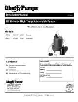
Figura 12. Configuración de ejemplo de QuickTree
Cubierta de acceso serie 700
La cubierta serie 700 contiene acceso a los sellos de
entrada/salida del cable de alarma y flotación. Consulte la Figura 8
para estas ubicaciones.
QuickTree no está disponible en los sistemas de la serie 700. El
flotador de control de la bomba está conectado a la bomba
mientras el flotador de la alarma está en la tubería de descarga.
Servicio eléctrico y operación
Desconecte siempre las bombas de las fuentes de
alimentación antes de manipular o realizar cualquier ajuste en
las bombas, el sistema de bomba o el panel de control.
Toda
la instalación y el mantenimiento de bombas, controles,
dispositivos de protección y cableado general deben ser
realizados por personal calificado.
No quite el cable y el alivio de tensión, y no conecte el
conducto a la bomba.
La bomba debe estar correctamente conectada a tierra
utilizando el conductor de conexión a tierra suministrado. No
puentee los cables de conexión a tierra ni quite la conexión a
tierra de los enchufes. Si el sistema de la bomba no se
conecta a tierra correctamente, se pueden energizar todas las
partes metálicas de la bomba y sus alrededores.
No manipule ni desenchufe la bomba con las manos
mojadas,
mientras esté de pie sobre una superficie húmeda o
en agua, a menos que use el equipo de protección personal.
No levante ni transporte una bomba o un conjunto de
flotador por el lado del cable de alimentación. Esto dañará el
cable
de alimentación y podría exponer los hilos bajo tensión
dentro del cable.
El
suministro de energía eléctrica se debe ubicar dentro de las
limitaciones de longitud del cable de alimentación de la
bomba, y para las instalaciones por debajo del nivel del suelo,
debe ser de al menos 4 pies (1.22 m) por encima del nivel del
suelo.
Proteja el cable de alimentación del medio ambiente. Los
cables de alimentación y de interruptor desprotegidos
pueden
permitir que el agua se filtre a través de los extremos
en la bomba o en la carcasa del interruptor y, de esta forma,
energizar el entorno.
No
use un cable de extensión para alimentar el producto. Los
cables de extensión pueden sobrecargar tanto el producto
como los hilos de suministro del cable de extensión. Los hilos
sobrecargados se pueden calentar mucho y prenderse fuego.
Este producto requiere un circuito derivado separado, con
fusibles adecuados y conectado a tierra, dimensionado para
los requisitos de voltaje y amperaje de la bomba, como se
indica en la placa de identificación. Los cables de circuitos
derivados sobrecargados se pueden calentar mucho y
prenderse fuego.
No utilice este producto con líquidos inflamables o
explosivos como gasolina, aceite combustible, queroseno,
etc., como así tampoco en sus cercanías. Si los elementos
giratorios dentro de la bomba golpean cualquier objeto
extraño, pueden producirse chispas. Las chispas podrían
encender líquidos inflamables.
1 3.5”
2 3.5”
3 3.0”
4
3.5”
SE MUESTRA LA SERIE P370
Las posiciones 1, 2, 3, y 4 de los
flotadores están identificadas
por un estampado e la barra de
acero inoxidable. 1 es el nivel
más alto y 4 el más bajo.
Flotador de alarma
Flotador de control
de la bomba
Longitud de amarra
1
2
4
3 (en el lado opuesto)
ADVERTENCIA
RIESGO DE SHOCK ELÉCTRICO
ADVERTENCIA
RIESGO DE FUEGO
La page charge ...
La page charge ...
La page charge ...
La page charge ...
La page charge ...
La page charge ...
La page charge ...
La page charge ...
La page charge ...
La page charge ...
La page charge ...
La page charge ...
La page charge ...
La page charge ...
La page charge ...
La page charge ...
-
 1
1
-
 2
2
-
 3
3
-
 4
4
-
 5
5
-
 6
6
-
 7
7
-
 8
8
-
 9
9
-
 10
10
-
 11
11
-
 12
12
-
 13
13
-
 14
14
-
 15
15
-
 16
16
-
 17
17
-
 18
18
-
 19
19
-
 20
20
-
 21
21
-
 22
22
-
 23
23
-
 24
24
-
 25
25
-
 26
26
-
 27
27
-
 28
28
-
 29
29
-
 30
30
-
 31
31
-
 32
32
-
 33
33
-
 34
34
-
 35
35
-
 36
36


Liberty Pumps P382LE41 Mode d'emploi
- Taper
- Mode d'emploi
dans d''autres langues
Documents connexes
-
Liberty Pumps P382XPRG101V/A2W Mode d'emploi
-
 Liberty Pumps PRG101A Mode d'emploi
-
 Liberty Pumps 331 Manuel utilisateur
-
 Liberty Pumps P382XPRG102-2/A2 Guide d'installation
-
 Liberty Pumps HT40-Series Mode d'emploi
-
-
 Liberty Pumps LSGX203M Guide d'installation
-
Liberty Pumps 404L Mode d'emploi
-
 Liberty Pumps 404CV Guide d'installation
-
 Liberty Pumps PC237-442-10A Mode d'emploi


Autres documents
-
Bticino 339313 Mode d'emploi
-
Camco 39403 Guide d'installation
-
HP (Hewlett-Packard) LSG203M Manuel utilisateur
-
Little GIANT 620000 Guide d'installation
-
Flotec FP400C Le manuel du propriétaire
-
Superior Pump 92010 Manuel utilisateur
-
Jones Stephens S62304 Guide d'installation
-
Hydromatic 24"x24" Sewage Basin Packages Le manuel du propriétaire
-
Multinautic 19217 Guide d'installation
-
SJE RHOMBUS SJE MegaMaster Guide d'installation