CREE LIGHTING KBL-C Wireless Emergency Guide d'installation
- Taper
- Guide d'installation

KBL-C Series
Wireless Highbay LED Luminaire with Emergency Driver
Universal Hook and Cord or Pendant Mount
1 of 6 LPN00881X0004A0_B
INSTALLATION INSTRUCTIONS
INSTRUCTIONS D’INSTALLATION
IMPORTANT SAFEGUARDS
When using electrical equipment, basic safety precautions should
always be followed including the following:
READ AND FOLLOW ALL SAFETY
INSTRUCTIONS
1. DANGER- Risk of shock- Disconnect power before installation.
DANGER - RISQUE DE CHOC - COUPER L’ALIMENTATION
AVANT L’INSTALLATION
2. This luminaire must be installed in accordance with the NEC or your
local electrical code. If you are not familiar with these codes and
requirements, consult a qualied electrician.
Ce produit doit être installé conformément à NEC ou votre code
électrique local. Si vous n’êtes pas familier avec ces codes et ces
exigences, veuillez contacter un électricien qualié.
3. To reduce the risk of electric shock, disconnect both standard
and emergency power supplies and converter connector of the
emergency driver before servicing.
Pour réduire le risque de décharge électrique, vous devez
déconnecter à la fois le disjoncteur divisionnaire ou les fusibles et les
alimentations d’urgence avant l’entretien.
4. Do not use outdoors.
Ne pas utiliser à l’extérieur.
5. Do not let power supply cords touch hot surfaces.
Ne laissez pas les cordons d’alimentation toucher les surfaces
chaudes.
6. Do not mount near gas or electric heaters.
Ne montez PAS près des appareils de chauage de gaz ou électriques.
7. Equipment should be mounted in locations and heights where it will not readily be subjected to tampering by unauthorized personnel.
L’équipement doit être monté dans des endroits et à des hauteurs où il ne sera pas soumis à des altérations par des personnes non autorisées.
8. The use of accessory equipment not recommended by the manufacturer may cause an unsafe condition.
L’utilisation d’accessoires non recommandés par le fabricant peut causer une situation dangereuse.
9. Suitable for damp location.
Convient aux emplacements humides.
10. Maximum ambient operating temperature: 9L, 12L, and 18L = 50°C and 24L, 30L, and 35L= 40°C.
Température ambiante maximale de fonctionnement: 9L, 12L, and 18L = 50°C and 24L, 30L, and 35L= 40°C.
11. MIN 90°C SUPPLY CONDUCTORS
LES FILS D’ALIMENTATION 90°C MIN.
12. Check to make sure that all input power connections have been properly made and the module is grounded to avoid potential electrical shock.
13. This equipment should be installed and operated with a minimum distance 20cm between the radiator and your body.
L’équipement doit etre installe d’une facon qu’une distance minimum de 20cm soit maintenue entre l’emetteur et toute partie du corps.
14. DO NOT lift luminaire by the power cord or any of the cables connected to the LED heatsink and LED driver.
15. All electrical connections for the sensor have been made at the factory.
16. The sensor is designed for mounting heights between 8 ft. to 40 ft. (2.4 m to 12.2 m).
17. When mounting heights are above 30ft. (9.1 m), the sensor generally only detects large objects such as forklift trucks.
18. When the sensor lens assembly is removed the exposed sensor body is sensitive to electrostatic discharge. Take the necessary steps to avoid
possible damage to the sensor.
19. Use Class 1 Wiring methods ONLY
SAVE THESE INSTRUCTIONS FOR FUTURE REFERENCE
NOTES:
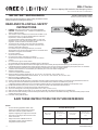
• For each mounting application below, when
mounting to surface ensure that the mounting
surface and customer supplied hardware is
capable of supporting the weight of the luminaire.
• The center of mounting is NOT the same as the
center of luminaire.
• Images used in this installation sheet are
for illustration purpose, there are dierent
congurations of the luminaire.
KBL EB
WIRELESS
KBL EB WIRELESS
WITH UL NETWORK
SENSOR
Maximum Mounting Height
With Acrylic
Reflector
With Acrylic
Reflector w/Conical
Lens
Short Acrylic
Reflector
Short Acrylic
Reflector w/Conical
Lens
42’ (12.8m) 32’ (9.8m) 39’ (11.9m) 32’ (9.8m)

2 of 6
LPN00881X0004A0_B
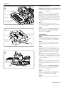
3
TO INSTALL:
2
“L” Channel
Pendant Mount Hole
3/4” (19mm) IP, 1.125”
(29mm) O.D.
1/2” (13mm) IP,
0.875” (22mm)
O.D. Knockouts
3/4” (19mm) IP,
1.125” (29mm)
O.D. Knockouts
Pendant Adjustment
Hinged Splice
Box
Pendant Slider
Plate
1
Luminaire Hook
Hook Adjustment
Screws
Retainer Spring
1/2” (13mm) IP,
0.875” (22mm)
O.D. Knockout
HOOK AND CORD MOUNT
STEP 1:
Push down on retainer spring until top of spring is free of
luminaire hook. See Figure 1.
STEP 2:
Slide hook into securely mounted customer supplied eye
hanger and return retainer spring to original position.
NOTE: The luminaire should already be factory set for
correct balance. If necessary, the fixture may be balanced
by loosening the hook adjustment screws on the top of
the housing and sliding the hook as necessary for correct
balance. Tighten hook adjustment screws when finished.
See Figure 1.
STEP 3:
Remove hinged splice box from top of housing by
loosening screw and sliding box to the right and up from
“L” channel. See Figure 2.
STEP 4:
Make wire connections per Electrical Connections and
then push the leads into hinged splice box. Replace the
plate and screw. Close the hinged splice box and re-
tighten the screw. See Figure 3.
PENDANT MOUNT
STEP 1:
Remove hinged splice box from top of housing by
loosening screw and sliding box to the right and up from
“L” channel. Unhook from hinge holes. See Figure 2.
STEP 2:
Remove hook, slider plate and cord and discard. Plug
junction box knockout hole with provided junction box
plug.
STEP 3:
Attach the supplied pendant mount slider plate using
(2) supplied screws. Use 3/4” threaded pendant, along
with two customer supplied locknuts (one for inside the
hinged splice box and one for outside the splice box).
Pull supply leads into position from customer supplied
conduit.
Note: If necessary, the luminaire may be balanced by
loosening (2) screws for pendant adjustment on the top of
the hinged splice box and sliding the adjustment plate as
necessary for correct balance. Tighten (2) screws when
finished. See Figure 2.
STEP 4:
Attach one end of the hinged splice box to luminaire by
aligning hinge slots on Mounting Bracket with hinges (on
splice box), and then inserting the hinges into the slots.
STEP 5:
Make wire connections per Electrical Connections and
then push the leads into hinged splice box. Replace the
plate and screw. Close the hinged splice box and re-
tighten the screw. See Figure 3.
STEP 6:
Secure other end of the hinged splice box to luminaire
by sliding screw on Mounting Bracket up and over in “L”
channel on the hinged splice box. See Figure 2.
STEP 7:
Secure luminaire to hinged splice box by tightening
screw.
Hinged
Splice Box Hinged Splice Box
Screw

3 of 6
LPN00881X0004A0_B
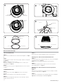
REFLECTOR INSTALLATION
TOOL LESS REFLECTOR:
STEP 1:
Place the reflector tabs between the luminaire mounting tabs. See Figure
4.
Step 2:
Turn the reflector clockwise until it locks into place under the locking tab.
See Figure 4.
NOTE: For additional reflector security
#6 x 5/16” self tapping screws can be added to the screw holes in the
mounting tabs. See Figure 4.
Step 3:
To remove the reflector, lift the locking tab and turn the reflector counter-
clockwise.
STANDARD REFLECTOR:
STEP 1:
Loosen the (4) screws, shown in Figure 5, at least 0.1 inch from the
heatsink.
NOTE: The view in Figure 5 is of the underside of the luminaire.
STEP 2:
Bring trim into housing and line up the (4) screws from Step 1, with the
keyhole slots on the reflector.
STEP 3:
Rotate trim, turn clockwise and tighten the (4) screws from Step 1.
Mounting Lens or Wire Guard To Aluminum Reflector
STEP 1:
Secure the hinge retainer and frame hinge to the reflector using supplied
screw and lock nut. See Figure 6.
NOTE: Reflector is pre-punched at position of this installation.
STEP 2:
Swing the wire guard into place and secure to the reflector with the
attached spring latch. See Figure 6.
Mounting Lens or Wire Guard To Prismatic/ Polycarbonate
Reflector
STEP 1:
Place lens or wire guard onto the bottom of reflector, and place V-band
around lens and reflector. See Figure 7.
STEP 2:
Secure lens or wire guard to reflector by tightening screw on V-band(See
Figure 7) or installing spring on V-band (See Figure 8).
6
Reflector Hinge Retainer
Frame Hinge
Mounting Ring
Reflector
Lens with V-band
Screw
7
Reflector
Lens with V-band
Spring
8
Luminaire
Mounting Tabs
Luminaire
Mounting Tabs
Screw
Holes
Locking
Tab
45Loosen
Screws

4 of 6
LPN00881X0004A0_B
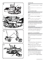
SITE MAP LABEL
STEP 1:
Remove unit site map label SNAP address. See Figure
9.
STEP 2:
Apply site map label to the correct position on the site
map. See
Figure 9.
INSTALLING SAFETY CABLE
NOTE: Safety Cable is sold separately as an accessory,
please refer to installation sheet in safety cable
packaging for complete installing instructions.
STEP 1:
Attach one end of the safety cable through the hole on
the lower housing (either side). See Figure 10.
STEP 2:
Attach other end of the safety cable to mounting
surfaces using customer supplied hardware.
SYSTEM COMMISSIONING AND CUSTOMIZING
System commissioning is required for the fixtures to
be recognized on the Simply SNAP network. Contact
Cree Lighting at 800-236-6800 for more details about
commissioning and customizing.
SENSOR INFORMATION
For programming of sensor and more detailed
description of sensor visit https://legrand.us/lighting-
controls-and-systems/occupancy-and-vacancy-
sensors/in-fixture-sensors/line-low-voltage-0-10v-
pir-fix-sens-120-277vac-no-ir-conf/p/fsp-202.
INSTALLING UL (120V-277V)SENSOR
NOTE: Ensure that you remove the label on the unit
that says, “Remove This Label Before Installing Lens”.
If this label is not removed, the sensor will not work
properly.
STEP 1:
Rotate the wire form up as shown. The wire form will
snap into position to hold the Sensor horizontal. See
Figure 11.
STEP 2:
Locate the wire form on the sensor and install onto
the luminaire by inserting the wire form into the (2)
tabs under the driver box. See Figure 12.
NOTE: The FSP-202 sensor has been preset with
the optimal settings to provide the widest range of
user flexibility and performance of the Synapse
Environment. Sensor characteristics can be modified
in the Synapse user interface.
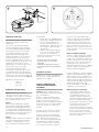
INSTALLING REMOTE SENSOR
NOTE: Install Clamp onto beam and turn Bolt until
it contacts the beam, torque Beam Clamp Bolt an
additional 1/4-1/2 of a turn after bolt contacts the
beam. Insure clamp is secure prior to adjusting
Sensor position. See Figure 13 on the next page.
The remaining 2 screws can be used to fine tune the
position/view of the Sensor. See Figure 13 on the next
page.
Safety Cable
Wire Form
11
Wire
Form
Driver Box
Tabs
Sensor Adjustment
Screw
10
12
9
Site Map Label

5 of 6
LPN00881X0004A0_B
SENSOR DESCRIPTION
The FSP-202 is a motion sensor that controls
lighting levels based on occupancy and
ambient light.
The sensor uses passive infrared (PIR)
sensing technology that reacts to changes
in infrared energy (moving body heat) within
the coverage area. Once the sensor stops
detecting movement and the time delay
elapses, lights will go from high to low
mode and eventually turn off if it is desired.
Sensors must directly “see” motion of a
person or moving object to detect them, so
careful consideration must be given to sensor
luminaire placement and lens selection.
Avoid placing the sensor where obstructions
may block the sensor’s line of sight.
The FSP-202 is designed for indoor
environments. The FSP-202 is preset from
Cree Lighting to optimize functionality and
flexibility of the sensor’s behavior through the
Synapse user interface. Factory settings from
Cree Lighting are listed below. See Figure 14.
KBL Wireless FSP-202 Settings:
Mode = C
Dim = 10V
Time = 30s
EMERGENCY DRIVER CHECK
NOTE: For short-term testing of the
emergency function, the battery must be
charged for at least one hour. The emergency
driver must be charged for at least 24 hours
before conducting a long-term test.
STEP 1:
When AC power is applied, the charging
indicator light is illuminated, indicating the
battery is being charged. When power fails,
the emergency driver automatically switches
to emergency power, operating the LED array.
When AC power is restored, the emergency
driver returns to the charging mode.
STEP 2:
Although no routine maintenance is required
to keep the emergency driver functional, it
should be checked periodically to ensure
that it is working. The following schedule is
recommended:
• Visually inspect the charging indicator
light monthly. It should be illuminated.
• Test the emergency operation of
the fixture at 30-day intervals for a
minimum of 30 seconds. When the test
switch is depressed, the LED array
should operate.
• Conduct a 90-minute discharge test
once a year. The LED array should
operate for at least 90 minutes.
If the luminaire fails any of these checks,
consult service personnel.
REFER ANY SERVICING INDICATED
BY THESE CHECKS TO QUALIFIED
PERSONNEL
EMERGENCY DRIVER AND AC DRIVER
MUST BE FED FROM THE SAME BRANCH
CIRCUIT.
TECHNICAL SUPPORT
If unable to successfully resolve problems
with the sensor, call 800-236-6800 for Cree
Lighting technical support.
FEDERAL COMMUNICATION
COMMISSION INTERFERENCE
STATEMENT
CAUTION: Changes or modifications not
expressly approved could void your authority
to use this equipment.
This device complies with Part 15 of the
FCC Rules. Operation to the following two
conditions: (1) This device may not cause
harmful interference, and (2) this device must
accept any interference received, including
interference that may cause undesired
operation.
The LED in the front of this device operates
within Risk Group 1 levels per IEC 62471.
This device has been tested and found to
comply with the limits for a Class A digital
device, pursuant to Part 15 of the FCC
Rules. These limits are designed to provide
reasonable protection against harmful
interference when the device is operated
in a commercial environment. This device
generates, uses, and can radiate radio
frequency energy and, if not installed and
used in accordance with the instruction
manual, may cause harmful interference
to radio communications. Operation of this
device in a residential area is likely to cause
harmful interference in which case the user
will be required to correct the interference at
his own expense.
INDUSTRY CANADA STATEMENT
This device complies with Industry Canada
licence-exempt RSS standard(s). Operation
is subject to the following two conditions: (1)
this device may not cause interference, and
(2) this device must accept any interference,
including interference that may cause
undesired operation of the device. In addition,
this device complies with ICES-005 of the
Industry Canada (IC) Regulations.
Le présent appareil est conforme aux CNR
d’Industrie Canada applicables aux appareils
radio exempts de licence. L’exploitation est
autorisée aux deux conditions suivantes : (1)
l’appareil ne doit pas produire de brouillage,
et (2) l’utilisateur de l’appareil doit accepter
tout brouillage radioélectrique subi,
même si le brouillage est susceptible d’en
compromettre le fonctionnement.
Radiation Exposure Statement:
• This equipment complies with FCC
radiation exposure limits set forth for
an uncontrolled environment. This
equipment should be installed and
operated with minimum distance 20 cm
between the radiator and your body.
• This transmitter must not be co-located
or operating in conjunction with any
other antenna or transmitter.
• The antennas used for this transmitter
must be installed to provide a separation
distance of at least 20 cm from all
persons and must not be co-located or
operating in conjunction with any other
antenna or transmitter.
14
Remove lens to access dials
13
Torque clamp bolt
¼-1/2 Turn

6 of 6 LPN00881X0004A0_B
www.creelighting.com
© 2023 Cree Lighting USA LLC. All rights reserved. For informational purposes only. Content is subject to change. See www.
creelighting.com/warranty for warranty and specifications. Cree® and the Cree Lighting logo are registered trademarks of
SMART Global Holdings, Inc. NEMA® is a registered trademark of the National Electrical Manufacturers Association. The
Synapse® is a registered trademark of Synapse Wireless, Inc.
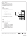
ELECTRICAL CONNECTIONS
NOTE: Luminaire is intended to be wired to a specific voltage.
Make sure that supply voltage matches voltage on electrical
label next to the junction box. Connecting luminaire to voltage
other than that specified on the label may result in luminaire
damage and/or improper luminaire operation. The emergency
driver must be fed from the same branch as the AC Driver.
ELECTRICAL CONNECTIONS MADE IN JUNCTION BOX
STEP 1:
Supply connections can be brought to the junction
box using customer supplied conduit.
STEP 2:
Using customer supplied 90°C minimum rated wire connectors,
make the following electrical connections within the junction box.
a. Connect the black luminaire lead to
the voltage supply hot lead.
b. Connect the white/red luminaire lead
to the supply switched hot.
c. Connect white luminaire lead to the neutral supply lead.
d. Connect green lead to the supply ground lead.
e. If 0/1-10v Dimming is used, connect the violet
lead to the supply positive dimming lead.
f. If 0/1-10v Dimming is used, connect the grey or
pink lead to the supply negative dimming lead.
STEP 3:
Locate the two white leads with connectors located inside the
luminaire junction box and connect them.
ELECTRICAL CONNECTIONS MADE WITH CORD
STEP 1:
Supply connections for dimming leads can be brought to
the junction box using customer supplied conduit.
STEP 2:
Make the following connection from the cord
to customer supplied junction box.
a. Connect the black luminaire hot lead
to the voltage supply lead.
b. Connect the red luminaire lead to the supply switched hot.
c. Connect white luminaire lead to the neutral supply lead.
d. Connect green wire lead to the supply ground lead.
e. If 0/1-10v Dimming is used, connect the violet lead to the
supply positive dimming lead in the luminaire junction
box using 90°C minimum rated wire connectors .
f. If 0/1-10v Dimming is used, connect the grey or pink lead
to the supply negative dimming lead in the luminaire
junction box using 90°C minimum rated wire connectors.
STEP 3:
Locate the two white leads with connectors located inside the luminaire junction box and connect them..
BLACK
WHITE
DIM (-) GREY
OR PINK
DIM (+) VIOLET
NEUTRAL
VIOLET
GREY OR PINK
SUPPLY WIRING
(DIMMING OPTIONAL)
LUMINAIRE
JUNCTION BOX
VIOLET +
VIOLET
BROWN -
BROWN
ITS
GROUND GREEN
WALL SWITCH
HOT
RED (FOR CORD)
OR
WHITE/RED (FOR
NO CORD)
SWITCHED HOT
HOT
-
 1
1
-
 2
2
-
 3
3
-
 4
4
-
 5
5
-
 6
6


CREE LIGHTING KBL-C Wireless Emergency Guide d'installation
- Taper
- Guide d'installation
dans d''autres langues
Documents connexes
Autres documents
-
Warehouse Lighting WAREHOUSE-LIGHTING Adjustable Linear High Bay Manuel utilisateur
-
Lightolier Calculite Retrofit and Remodelers Install Instructions
-
Lightolier IS-CAEM Emergency Pack Install Instructions
-
Eaton CROUSE-HINDS Champ PFMA Series Installation & Maintenance Information
-
-
-
Eaton Portfolio LDSQA4 Installation Instructions Manual
-
Cooper Lighting LDSQ4B LED Housing LED Reflector Downlight Reflector Manuel utilisateur
-
-
SYNAPSE EMB-S2-FW Controller Manuel utilisateur