K RCHER BD 70/75 W Classic Bp Vacuum Cleaner Manuel utilisateur
- Taper
- Manuel utilisateur


A

BCD
E F G
1
H
1
1
2
I J
K L M
1
N
10 mm
12 3
O P
1.
2.
Q R S

1
T
12
U V
W X Y

6 English
Contents
IMPORTANT SAFETY INSTRUCTIONS
READ ALL INSTRUCTIONS BEFORE USING THIS APPLI-
ANCE
몇WARNING
To reduce the risk of fire, electric shock, or injury:
DO NOT LEAVE appliance unattended when plugged in. Unplug-
from outlet when not in use and before servicing.
몇WARNING
TO REDUCE THE RISK OF ELECTRIC SHOCK-USE IN-
DOORS ONLY
●Do not allow to be used as a toy. Close attention is necessary
when used by or near children.
●Use only as described in this manual. Use only manufacturer’s
recommended attachments.
●Do not use with damaged cord or plug. If the unit is not working
as it should, has been dropped, damaged, left outdoors, or
dropped into water, return it to a service center.
●Do not pull or carry by the cord, do not use cord as a handle,
do not close a door on the cord, or pull cord around sharp edg-
es or corners. Do not run appliance over cord. Keep cord away
from heated surfaces.
●DO NOT UNPLUG BY PULLING CORD. To unplug, grasp
plug, not cord.
●Do not handle plug or appliance with wet hands.
●Do not put any objects into openings. Do not use if openings
are blocked; keep free of dust, lint, hair, and anything that may
reduce air flow.
●KEEP HAIR, CLOTHING, LOOSE JEWELRY, FINGERS and
all parts of the body away from openings and moving parts.
●Turn off all controls before unplugging.
●Use extra care when cleaning on stairs.
●Do not use to pick up flammable or combustible liquids, such
as gasoline, or use in areas where they may be present.
●Connect to a properly grounded outlet only. See Grounding In-
structions.
●Always disconnect cord from electrical outlet before servicing
appliance.
●Never sweep off explosive liquids, combustible gases or undi-
luted acids and solvents. This includes petrol, paint thinner or
heating oil which can generate explosive fumes or mixtures
upon contact with the air. Acetone, undiluted acids and sol-
vents must also be avoided as they can harm the materials on
the machine.
●Do not vacuum up burning or smouldering objects!
GROUNDING INSTRUCTIONS
This device must be grounded. If it should malfunction or break
down, grounding provides a path of least resistance for electric
current to reduce the risk of electric shock.
This device is equipped with a cord having an equipment ground-
ing conductor and ground plug.
The plug must be plugged into an appropriate outlet that is prop-
erly installed and grounded in accordance with all local codes and
ordinances.
DANGER
Improper connection of the equipmentgrounding conductor
can result in a risk of electrocution.
Check with a qualified electrician or service personnel if you are
in doubt as to whether the outlet is properly grounded.
Do not modify the plug provided with the product - if it will not fit
the outlet, have a proper outlet installed by a qualified electrician.
Do not use any type of adapter with this product.
This appliance is for use on a nominal 120-volt circuit and has a
grounding attachment plug that looks like the plug illustrated in
sketchpicture A.
Make sure that the appliance is connected to an outlet having the
same configuration as the plug.
No adaptor should be used with this appliance.
CONNECT TO A PROPERLY GROUNDED OUTLET ONLY
1Grounded outlet
2Grounded outlet box
3Grounded pin
OPERATING SAFETY RULES AND
PRACTICES
Owner/User Responsibility
The owner and/or user must have an understanding of the man-
ufacturer’s operating instructions and warnings before using this
device.
Warning information should be emphasized and understood.
If the operator is not fluent in English, the manufacturer’s instruc-
tions and warnings shall be read to and discussed with the oper-
ator in the operator’s native language by the purchaser/ owner,
making sure that the operator comprehends its contents.
Owner and/or user must study and maintain for future reference
the manufacturers’ instructions.
General
Before starting operation, the device must be in the operating po-
sition.
Do not start or operate the device, any of its functions or attach-
ments, from any place other than from the designated operator's
position.
Before leaving the operator’s position:
1 bring the device to a complete stop;
IMPORTANT SAFETY INSTRUCTIONS ......................... 6
OPERATING SAFETY RULES AND PRACTICES .......... 6
MAINTENANCE AND REBUILD PRACTICES ................ 7
FIRE SAFETY STANDARD ............................................. 7
General notes .................................................................. 7
Function ........................................................................... 7
Intended use .................................................................... 7
Environmental protection ................................................. 7
Warranty .......................................................................... 7
Accessories and spare parts............................................ 7
Scope of delivery ............................................................. 7
Safety instructions ........................................................... 8
Description of the unit ...................................................... 8
Installation........................................................................ 9
Initial startup .................................................................... 10
Operation ......................................................................... 11
Transport.......................................................................... 12
Storage ............................................................................ 12
Care and maintenance .................................................... 12
Troubleshooting guide ..................................................... 13
Accessories BD variant.................................................... 14
Accessories BR variant.................................................... 14
Accessories BD and BR variants..................................... 14
Technical data.................................................................. 15

English 7
2 if the device must be on an incline, block the wheels.
Maintain a safe distance from the edge of ramps, platforms, and
other similar working surfaces.
Do not add to, or modify the device.
Do not block access to fire aisles, stairways or fire equipment.
Traveling
Yield the right of way to pedestrians and emergency vehicles
such as ambulances and fire trucks.
Cross railroad tracks at an angle wherever possible. Do not park
closer than 6 ft (1800 mm) to the nearest rail of a railroad track.
Keep a clear view of the path of travel and observe for other traf-
fic, personnel, and safe clearances.
Under all travel conditions, operate the device at a speed that will
permit it to be brought to a stop in a safe manner.
Do not indulge in stunt driving or horseplay.
Slow down for wet and slippery floors. Before driving over a dock-
board or bridge plate, be sure that it is properly secured. Drive
carefully and slowly across the dockboard or bridge plate, and
never exceed its rated capacity.
When negotiating turns, reduce speed to a safe level consistent
with the operating environment. Make the turns smoothly.
Operator care of the device
If the device is found to be in need of repair or in any way unsafe,
or contributes to an unsafe condition, the matter shall be reported
immediately to the user’s designated authority, and the device
shall not be operated until it has been restored to safe operating
condition.
If during operation the device becomes unsafe in any way, the
matter shall be reported immediately to the user’s designated au-
thority, and the device shall not be operated until it has been re-
stored to safe operating condition.
Do not make repairs or adjustments unless specifically author-
ized to do so.
MAINTENANCE AND REBUILD PRACTICES
Operation of the device may be hazardous if maintenance is ne-
glected or repairs, rebuilds, or adjustments are not performed in
accordance with the manufacturer’s design criteria. Therefore,
maintenance facilities (on or off premises), trained personnel,
and detailed procedures shall be provided.
Maintenance and inspection of the device shall be performed in
conformance with the following practices:
1 a scheduled planned maintenance, lubrication, and inspection
system shall be followed; consult the manufacturer’s recom-
mendations.
2 Only trained and authorized persons shall be permitted to op-
erate a powered floor scrubber. Operators of powered floor
scrubbers shall be qualified as to visual, auditory, physical,
and mental ability to operate the equipment safely.
Avoid fire hazards and have fire protection equipment present in
the work area. Do not use open pans of fuel or flammable clean-
ing fluids for cleaning parts.
FIRE SAFETY STANDARD
Any device not in safe operating condition shall be removed from
service.
Repairs shall not be made in Class I, Class II, and Class III loca-
tions.
Fire Prevention.The device shall be kept in a clean condition
and reasonably free of lint, excess oil, and grease.
Noncombustible agents are preferred for cleaning the device.
Flammable liquids [those having flash points at or above 100°F
(37,8°C)] are not allowed. Precautions regarding toxicity, ventila-
tion, and fire hazard shall be appropriate for the agent or solvent
used.
Nameplate Visibility. The device type designations as shown on
the nameplate and the type markers shall not be covered over
with paint so that their identification information is obscured.
General notes
Read these original operating instructions and the
enclosed safety instructions before using the device
for the first time. Proceed accordingly.
Keep both books for future reference or for future owners.
Function
This scouring and vacuum machine is used for wet cleaning of
level floors.
The device can be adjusted to suit the respective cleaning task
by setting the water volume and detergent volume appropriately.
The detergent dosing is adjusted via the amount added to the
tank.
The working width and the capacity of the fresh and waste water
tanks (see chapter " Technical data) enable effective cleaning
with a long working time.
The device has a drive motor.
Note
The device can be equipped with various accessories to suit the
respective cleaning task. Request a copy of our catalogue or visit
our Internet website at www.kaercher.com.
Intended use
This device is suitable for commercial and industrial use, e.g. in
hotels, schools, hospitals, factories, shops, offices, and rental
companies. Use the device only in accordance with the informa-
tion in these operating instructions.
●The device may only be used for cleaning smooth surfaces
that are insensitive to water and polishing.
●The device is not suitable for cleaning frozen floors (e.g. in
cold stores).
●The device is not suitable for use in potentially explosive envi-
ronments.
●The device is approved for operation on surfaces with a max-
imum slope (see chapter Technical data).
Environmental protection
The packing materials can be recycled. Please dispose of
packaging in accordance with the environmental regula-
tions.
Electrical and electronic appliances contain valuable, recy-
clable materials and often components such as batteries, re-
chargeable batteries or oil, which - if handled or disposed of
incorrectly - can pose a potential threat to human health and the
environment. However, these components are required for the
correct operation of the appliance. Appliances marked by this
symbol are not allowed to be disposed of together with the house-
hold rubbish.
Notes on the content materials (REACH)
Current information on content materials can be found at:
www.kaercher.com/REACH
Warranty
The warranty conditions issued by our relevant sales company
apply in all countries. We shall remedy possible malfunctions on
your appliance within the warranty period free of cost, provided
that a material or manufacturing defect is the cause. In a warranty
case, please contact your dealer (with the purchase receipt) or
the next authorised customer service site.
(See overleaf for the address)
Accessories and spare parts
Only use original accessories and original spare parts. They en-
sure that the appliance will run fault-free and safely.
Information on accessories and spare parts can be found at
www.kaercher.com.
Scope of delivery
Check the contents for completeness when unpacking. If any ac-
cessories are missing or in the event of any shipping damage,
please notify your dealer.

8 English
Safety instructions
Before using the device for the first time, read and observe these
operating instructions and the accompanying brochure: Safety in-
formation for brush cleaning units spray retraction devices, No.
5.956-251.0.
The device is approved for operation on surfaces with a specified
limited slope (see Chapter Technical data).
몇WARNING
Risk of injury!
Device may tip over on sloping surfaces.
Do not operate the device on sloping surfaces.
The device may only be operated when the hood and all covers
are closed.
Safety devices
몇CAUTION
Missing or modified safety devices!
Safety devices are provided for your own protection.
Do not bypass, remove or render ineffective any safety devices.
Safety switch
The device switches off when the safety switch is released.
Key-operated switch
Pulling the key out of the key-operated switch secures the device
against unauthorised use.
Warning symbols
Observe the following warnings when handling the batteries:
Description of the unit
Overview of front side
1Push handle
2Safety switch
3Waste water tank cap
4Homebase retaining rail
5Waste water tank
6** Battery
7Fresh water filter
8Fresh water tank lock
9Pedal for brush replacement
10 Disc brush
11 Fresh water tank
12 Hose holder
13 Fresh water tank filling hole
** Not in scope of delivery
Overview of rear
1Waste water drain hose with dosing unit
2Cleaning head
3Pedal for brush replacement
4Suction hose
5Suction bar inclination adjustment
6Wing nuts for fastening the suction bar
7Suction bar height adjustment
8Suction bar
9Fresh water filling level indicator
Fresh water drain hose
10 Cleaning head lever
11 Water volume regulation knob
12 Suction bar lever
13 Battery plug connector
14 Key-operated switch
15 Display
16 Working speed rotary knob
17 Driving direction switch
Overview of R head
Illustration D
1R head
2Scraper roll
3Water distribution strip
4Side skirt
5Sweep bin
Overview of waste water tank
Illustration E
1Coarse dirt filter
2Fluff filter
3Float
Type plate
Illustration C
1Type plate
Colour coding
●Control elements for the cleaning process are yellow.
Observe notes in the instructions for the battery, on
the battery and in these operating instructions.
Wear eye protection.
Keep acids and batteries away from children.
Risk of explosion
Fire, sparks, open flames and smoking are prohibited.
Risk of acid burns
First aid.
Warning
Disposal
Do not throw batteries in the bin.

English 9
●Control elements for maintenance and servicing are light grey.
Symbols on the appliance
* optional
Installation
Unloading
1. Remove the carton.
2. Remove the straps.
3. Remove the wooden blocks fastened to the pallet by screws.
4. Using the 3 upper reinforcing boards of the carton packaging
and the securing board screwed laterally on the pallet, place a
ramp in front of the pallet and secure it using board pallet
screws.
Illustration F
Illustration G
1Securing board
2Beam
3Reinforcing board
5. Push the beam which has been unscrewed from the pallet un-
der the ramp for support and screw into place.
6. Press the cleaning head lever down and latch it in place.
7. Only for BD 80/100 and BR 85/100: Press the brake lever
down.
Illustration H
1Brake lever
Note
For BD 70/75 and BR 75/75, there is no brake. Releasing the
brake is not necessary with this device.
8. Pull the device backwards off the pallet.
9. Only for BD 80/100 and BR 85/100: Press the brake lever up.
Installing the suction bar
1. Insert the suction bar in the suction bar mount.
Illustration J
2. Tighten the wing nuts.
3. Fit the suction hose.
Batteries
Recommended battery sets BD 70/75 and BR 75/75
* Minimum volume of the battery charging room
** Minimum airflow between battery charging room and environ-
ment
For initial installation, an additional battery installation kit is re-
quired:
1 2638-198.0
2 2638-162.0
3 2638-106.0
Recommended battery sets BD 80/100 and BR 85/100
* Minimum volume of the battery charging room
** Minimum airflow between battery charging room and environ-
ment
For initial installation, an additional battery installation kit is re-
quired:
1 2638-162.0
2 2638-106.0
3 2638-197.0
Low-maintenance batteries (wet batteries)
DANGER
Danger of burns due to acid leakage!
Only fill the battery with water when it is discharged.
When handling battery acid, use safety goggles and immediately
rinse out any acid splashes on the skin or clothing with water.
ATTENTION
Risk of damage to the batteries!
Using water with additives will void the battery’s warranty.
Top up the batteries using only distilled or desalinated water (EN
50272-T3).
Do not use any foreign additives or touch-up agents.
1. Add distilled water one hour before the charging process
comes to an end. Observe the correct acid level according to
the battery label.
All cells must produce gas at the end of the charging process.
Fresh water tank drain opening
Waste water tank drain opening
Increased cleaning head contact pressure
Battery access
Fresh water tank filling level (50%)
Insert the charger plug here
Lashing point
* Mop holder
ATTENTION
Incorrect socket
Risk of damage
DO NOT insert the charger plug here
Normal cleaning head contact pressure
Raise the cleaning head
Pedal for raising/lowering the cleaning head
Brush replacement pedal
Description Order no. Volume (m3)* Airflow (m3/
h)**
Only BD 70/
75 W
115 Ah - mainte-
nance-free
2.815-091.0 1) 1.98 0.792
170 Ah - mainte-
nance-free
2.815-092.0 2) 2.31 0.924
180 Ah - mainte-
nance-free
2.815-101.0 3) 4.785 1.914
Description Order no. Volume (m3)* Airflow (m3/
h)**
170 Ah - mainte-
nance-free
2.815-092.0 1) 2.31 0.924
180 Ah - mainte-
nance-free
2.815-101.0 2) 4.785 1.914
240 Ah - mainte-
nance-free
2.815-102.0 2) 6.27 2.508
285 Ah - mainte-
nance-free
2.815-095.0 3) 11.88 4.752

10 English
Maintenance-free batteries (AGM and gel batteries)
ATTENTION
Risk of damage from AGM and gel batteries!
Opening or drilling the battery housing will damage an AGM or
gel battery. It must then be replaced.
Do not open the battery housing and do not drill any holes.
Do not cover the pressure relief valve and do not change it.
1. Only charge AGM and gel batteries using the specified charg-
ers, see chapter: Charging the battery.
Installing and connecting batteries
몇WARNING
Risk of injury due to the device tipping over!
Device may tip over when removing and installing batteries.
Ensure that the device is positioned stably when removing and in-
stalling the batteries.
ATTENTION
Risk of damage to the control electronics!
The control electronics can be destroyed by reversing the polarity
of the battery connections.
Take care to ensure the correct polarity when connecting the bat-
teries.
몇WARNING
Danger to life from fire or explosion if batteries are deeply
discharged!
Incorrect charging of deeply discharged batteries can cause a
fire.
Do not start the device if the battery is deeply discharged.
Make sure that the battery is charged before starting the system.
1. Drain the waste water.
2. Pivot the waste water tank upwards.
3. Place the battery in the device as shown. Important: Push the
batteries all the way back!
BD 80/100 and BR 85/100
Illustration K
170 Ah, 2.815-092.0
180 Ah, 2.815-101.0
240 Ah, 2.815-105.0
285 Ah, 2.815-095.0
1Spacers
Illustration L
BD 70/75 and BR 75/75
115 Ah, 2.815-091.0
170 Ah, 2.815-092.0
180 Ah, 2.815-101.0
1Spacers
2Battery holder
3Additional weights
4. Insert a spacer between the right batteries and the fresh water
tank,
afor 115 Ah battery set: 1 piece lengthwise flat.
bfor battery sets other than 115 Ah: 2 pieces lengthwise
upright on top of each other.
5. For BD 70/75 with 115 Ah battery set: Insert the 4 additional
weights.
6. Attach the battery fastener, to do so
afor BD 70/75: Install the 2 battery holders and for 115 Ah:
Tighten at the left and middle threaded holes.For BR 75/75
and BD 70/75: 170 Ah / 180 Ah: Tighten at the right and
middle threaded holes.
bFor BD 80/100 and BR 85/100: Insert one or two spacers
flat lengthwise or vertically between the front batteries and
the fresh water tank so that the batteries cannot slip forward.
7. Connect the poles to the connection cables from the battery in-
stallation kit.
8. Clamp the connecting cables on the (+) and (-) battery termi-
nals that are still free.
9. Connect the device-side battery connector to the battery-side
battery connector.
10.Pivot the waste water tank downwards.
Removing the batteries
몇WARNING
Risk of injury due to the device tipping over!
Device may tip over when removing and installing batteries.
Ensure that the device is positioned stably when removing and in-
stalling the batteries.
1. Turn the key-operated switch to "0" and remove the key.
2. Disconnect the battery plug.
3. Drain the waste water.
4. Pivot the waste water tank upwards.
5. Disconnect the device-end cable from the negative terminal of
the battery.
6. Disconnect the remaining cables from the batteries.
7. For BD 80/100: Remove the spacer(s) between the front bat-
teries and the fresh water tank.
8. For 115 Ah battery set: Take out the additional weights.
9. Remove the batteries.
10.Dispose of the used batteries in accordance with statutory
provisions.
Initial startup
Charging the battery
DANGER
Risk of injury from charger!
Electric shock due to improper use of the charger!
Adhere to the mains voltage and fuse values specified on the de-
vice type plate.
Only use the charger in dry rooms with sufficient ventilation.
ATTENTION
Danger of explosion due to battery!
Gases accumulate under the tank during the charging process.
Pivot the waste water tank upwards before charging low-mainte-
nance batteries.
ATTENTION
Risk of damage due to unsuitable charger!
Do not connect the charger to the device-side battery connector.
Use only a charger suitable for the type of battery installed.
Read the operating instructions of the charger manufacturer and
observe the safety instructions in particular.
The average charging time is approx. 10-15 hours.
The device cannot be used during the charging process.
Note
The device has deep discharge protection, i.e. the brush motor
and turbine are switched off automatically when the permitted
minimum capacity level is reached.
1. Drive the device directly to the charger and do not drive on
slopes.
2. Pull out the device-side battery connector.
Illustration I
1Battery plug, device side
2Battery plug, battery side
3. Connect the battery-side battery connector to the charger.
4. Plug the mains plug of the charger into the socket.
5. Carry out the charging process in accordance with the operat-
ing instructions for the charger.
6. Connect the device-side battery connector to the battery-side
battery connector.
Battery set Capacity Charger
2.815-091.0 115 Ah 6654-367.0
2815-092.0 170 Ah 6654-436.0
2815-101.0 180 Ah 6654-434.0
2815-105.0 240 Ah 6654-437.0
2815-095.0 285 Ah 6654-419.0

English 11
Operation
ATTENTION
Risks during operation
Danger of injury
Release the safety switch in the case of danger.
Filling with operating materials
Filling fresh water
1. Open the fresh water tank cap.
2. Fill fresh water (maximal 122 °F (50 °C)) to the lower edge of
the filling nozzle.
Note: The fresh water hose can be clamped with the hose
holder during filling.
3. Close the fresh water tank lock.
Notes on detergents
몇WARNING
Risk of damage to the device!
If unsuitable detergents are used, the device may get damaged.
Use only recommended detergents. The operator carries all in-
creased risks relating to operational safety and increased risk of
accidents if using other detergents.
Use only detergents free of solvents, salt and hydrofluoric acid.
Adhere to the safety instructions stated on the detergent packag-
ing.
Note
Do not use heavily foaming detergent.
Recommended detergents
Detergent
1. Fill the detergent into the fresh water tank.
Note: The cap for the fresh water tank filling hole can be used
for measuring the correct quantity of detergent. It has a meas-
uring scale marked on the inner side.
Adjusting the water volume
1. Adjust the water volume via the regulating knob to suit the de-
gree of soiling of the floor covering.
Note
Perform initial cleaning tests with a low water volume. Increase
the water volume step by step until achieving the desired clean-
ing result.
Note
The cleaning head continues operating without a liquid supply if
the fresh water tank is empty.
Adjusting the suction bar
Adjusting the inclination
The inclination must be adjusted so that the suction lips of the
suction bar make even contact with the floor over the entire
length of the suction bar.
1. Loosen the screw.
Illustration N
1Screw
2. Adjust the inclination of the suction bar.
3. Tighten the screw.
Adjusting the height
The height adjustment affects the bending of the suction lips on
contact with the floor.
1. Push the device a small distance forwards.
2. Compare the bending of the suction lips with the figure below.
Illustration O
´
1Spacer roller with holder
2Washer
3Screw
3. Unscrew the screw.
4. Insert a sufficient number of washers between the suction bar
and spacer roller to create the correct bending of the suction
lip.
5. Fit the remaining unused washers above the spacer roller.
6. Screw in and tighten the screw.
7. Repeat the entire procedure at the second spacer roller.
8. Push the device a small distance forwards.
9. Check the bending of the suction lips over the entire length.
10.Repeat the adjustment procedure if necessary.
Cleaning
Switching on the device
1. Turn the key-operated switch to "1".
The display shows the following one after the other:
●Period of time until the next after-sales Customer Service
●Software version, control panel
●Charging state of the battery and number of operating hours
Driving
Note
The direction of travel can be changed during the cleaning oper-
ation. This way, a certain position can be intensively cleaned by
driving back and forth several times.
1. Set the driving direction switch to "forward".
Note
To reduce the vehicle width, the suction bar can be mounted on
the transport holder. Narrow passages can be easily passed
through in this way.
Cleaning
Note
The inclination and height of the suction bar can be adjusted to
improve the vacuuming results (see chapter Adjusting the suc-
tion bar).
Note
When the waste water tank is full, the float switch closes the suc-
tion opening and the suction turbine runs at a higher speed. In
this case, raise the suction bar and drive to the location for emp-
tying the waste water tank.
1. Turn the working speed rotary knob to the desired value.
The speed is shown on the display during the adjustment. The
display is shown in percentage of the maximum speed.
2. Set the water volume at the regulating valve.
3. Press the suction bar lever downwards.
The suction bar lowers.
Vacuuming begins.
4. Press the cleaning head lever downwards, unlatch it and allow
it to move upwards.
5. Pull the safety switch towards the push handle.
The cleaning head starts up and the device moves at the set
speed.
Increasing brush contact pressure (BD variant only)
1. Let go of the safety switch.
2. Lift the cleaning head lever up with your hand and latch it to-
wards the right.
Application Detergent
Floor maintenance cleaner extra low foam-
ing with EU Ecolabel
APPROX. 50 C
Highly wetting universal cleaner RM 756
Intensive alcohol cleaner for floors and
surfaces. Well-suited for hard rock such as
granite
RM 755
Fine stone cleaner, surfactant-free RM 753
Universal decoater, suitable for linoleum RM 754
Acidic vending machine basic cleaner.
Suitable for sanitary areas and construc-
tion cleaning
RM 751
Industrial maintenance cleaner RM 69
Industrial basic cleaner and alkaline de-
coater
RM 752
Surface disinfectant cleaner RM 732

12 English
Finishing operation
Finishing cleaning
1. Let go of the safety switch.
2. Press the cleaning head lever down and latch it in place.
3. Continue moving a short distance.
The residual water is vacuumed up.
4. Lift the suction bar.
The suction continues to run for 10 seconds.
5. Turn the key-operated switch to "0".
6. Charge the battery if necessary.
Draining the waste water
몇WARNING
Environmental pollution!
Environmental pollution due to improper disposal in waste water.
Observe the local waste water treatment regulations.
1. Remove the drain hose from the support and lower it over a
suitable collecting device.
Illustration P
2. Press the dosing unit together or kink the hose.
3. Open the dosing unit cover.
4. Drain the waste water. Regulate the water volume by pressing
or kinking.
5. Rinse the waste water tank with clear water.
Draining fresh water
1. Pull off the filling level indicator hose and swivel it down.
Quickly draining fresh water
1. Unscrew the fresh water tank cap.
2. Allow the fresh water to drain away.
3. Fit the fresh water tank cap and screw into place.
Note: Take care to ensure that the hose connection in the
fresh water tank cap is positioned at the lowest point in the
tank after screwing the cap in place.
Transport
DANGER
Driving on slopes
Risk of injury
Observe the maximum permissible inclination when driving the
device on slopes for loading and unloading purposes (see chap-
ter “Technical data”).
Drive slowly.
몇CAUTION
Failure to observe the weight
Risk of injury and damage
Be aware of the weight of the device during transport.
Only load the device with the assistance of another person or by
using the drive.
1. Press the cleaning head lever down and latch it in place.
2. Raise the suction bar.
3. Turn the key-operated switch to "1".
4. Select the travel direction at the travel direction switch.
5. Pull the safety switch towards the push handle.
6. When transporting in vehicles, secure the device against slip-
ping and tipping over according to the applicable guidelines.
Illustration Q
7. First fit the strap under the waste water tank.
Storage
몇CAUTION
Risk of injury and damage!
The device may tip over on sloping surfaces.
Be aware of the weight of the device during storage.
ATTENTION
Frost
Destruction of the device through freezing water
Drain all water from the device.
Store the device in a frost-free location.
●This device may only be stored indoors.
●Fully charge the batteries before storing them for a long peri-
od.
●Fully charge the batteries at least every month during storage.
Care and maintenance
DANGER
Risk of injury!
The device may start moving unexpectedly and cause injury.
Turn the key-operated switch to "0" and remove the key before
performing any work on the device.
Pull out the charger mains plug.
Drain and dispose of the waste water and fresh water.
Safety inspection/maintenance contract
You can agree on regular safety inspections or close a mainte-
nance contract with your dealer. Please seek advice on this.
Maintenance intervals
Each time after use
ATTENTION
Risk of damage!
Risk of damage to the device due to improper cleaning.
Do not spray the device with water and do not use aggressive de-
tergents.
A detailed description of the individual maintenance work is pro-
vided in Chapter Maintenance work.
Drain the waste water.
Rinse the waste water tank with clear water.
Clean the exterior of the device using a damp cloth, wetted
with a mild washing lye.
Check the fluff filter and clean if required.
Clean the coarse dirt filter.
Clean the coarse dirt filter.
Only BR variants: Remove and empty the coarse dirt recep-
tacle.
Only BR variants: Clean the water distribution channel.
Clean the suction lips, check for wear and adjust the height or
replace if necessary.
Check the disc brushes for wear and replace if necessary.
Charge the battery.
If the charging state of the battery is below 50%, charge the
battery fully and without interruption.
If the charging state of the battery is above 50%, only re-
charge the battery if the entire operating duration will be re-
quired when next used.
Weekly
When used regularly, charge the battery fully and without in-
terruption at least once a week.
Monthly
A detailed description of the individual maintenance work is pro-
vided in Chapter Maintenance work.
1. Drain the fresh water tank and flush out deposits.
2. Clean the fresh water filter.
3. Clean the float and fluff filter.
4. Check battery poles for oxidation, brush off if necessary. Make
sure the connection cables are firmly in place.
5. Clean the seals between the waste water tank and the cover,
check for leaks and replace if necessary.
6. Check the acid density of the cells if the batteries are not main-
tenance-free.
7. If the device is not used for a longer period of time, shut down
the device when the batteries are fully charged. Fully charge
the battery at least once a month.
Annually
Have the prescribed inspection performed by Customer Ser-
vice.

English 13
Maintenance work
Turn over or replace the worn suction lips
The suction lips must be turned over or replace when they have
worn down to the wear mark.
Illustration R
1Wear mark
2Suction lip
1. Remove the suction bar.
2. Unscrew the star handles.
Illustration S
3. Pull off the plastic parts.
4. Pull off the suction lips.
5. Push in the turned over or new suction lips.
6. Push on the plastic parts.
7. Screw in and tighten the star handles.
Cleaning the fresh water filter
1. Drain the fresh water (see Chapter Draining fresh water).
2. Unscrew the fresh water tank lock.
Illustration U
1Fresh water tank lock
2Fresh water filter
3. Pull out the fresh water filter and rinse with clean water.
4. Insert the fresh water filter.
5. Fit the fresh water tank lock.
Note: Take care to ensure that the hose connection in the
fresh water tank cap is positioned at the lowest point in the
tank after screwing the cap in place.
Cleaning the coarse dirt filter
1. Open the waste water tank cover.
Illustration T
1Coarse dirt filter
2. Pull the coarse dirt filter upwards and off.
3. Rinse off the coarse dirt filter under running water.
4. Reinsert the coarse dirt filter into the waste water tank.
Clean the float and fluff filter
1. Open the waste water tank cover.
Illustration V
1Latching hooks
2Float
3Fluff filter
4Float housing
2. Release the latching hooks.
3. Pull the float housing downwards and off.
4. Remove the float from the float housing and clean it.
5. Remove the fluff filter and clean it.
6. Assemble all parts in the reverse order.
Replacing the disc brushes
1. Raise the cleaning head.
2. Press the brush replacement pedal down, beyond the zone of
resistance.
Illustration W
1Brush replacement pedal
3. Pull the 1st disc brush sideways and out from underneath the
cleaning head.
4. Hold the new disc brush under the cleaning head, then press
upwards and latch it into position.
5. Repeat the procedure for the 2nd disc brush.
Replacing the roller brushes
1. Raise the cleaning head.
2. Pull out the brush replacement handle.
Illustration Y
1Brush replacement handle
2Bearing cover with squeegee blade
3Roller brush
3. Remove the bearing cover including the squeegee blade.
4. Pull out the roller brush.
5. Fit the new roller brush and centre it on the driver.
6. Install the bearing cover with the squeegee blade.
Note
Make sure the roller brush sits on the mounting mandrel and not
underneath.
7. Pivot the brush replacement handle upwards and latch it into
place.
8. Repeat the entire procedure at the other side.
Cleaning the water distribution strip
Illustration X
1Water distribution strip
2Unlocking button
1. Press lock in the direction of the arrow and hold it there.
2. Pivot water distribution strip forward.
3. Pull out water distribution strip lengthways.
4. Clean the water distribution strip.
5. Fit water distribution strip back into the cleaning head and
snap the lock into place.
Troubleshooting guide
DANGER
Risk of injury!
The device may start moving unexpectedly and cause injury.
Turn the key-operated switch to "0" and remove the key before
performing any work on the device.
Pull out the charger mains plug.
Drain and dispose of the waste water and fresh water.
Contact Customer Service in the case of malfunctions that
cannot be corrected using this table.
Malfunction Rectification
The device cannot be started 1. Turn the key-operated switch to "1".
2. Unlock the emergency stop button on the control panel by turning it. (Note: not all device versions
are equipped with an emergency stop button)
3. Actuate the safety switch.
4. Insert the battery plug.
5. Check the battery and charge if necessary.
6. Check that the battery terminals are correctly connected.
The water volume is insuffi-
cient
1. Check the fresh water filling level and fill the tank if necessary.
2. Increase the water volume at the water volume regulating knob.
3. Pull off the water distribution strip on the cleaning head and clean the water channel (BR variant
only).
4. Clean the fresh water filter.
5. Check the hoses for clogging and clean if necessary.

14 English
Accessories BD variant
Accessories BR variant
Accessories BD and BR variants
The suction performance is
too low
1. Shut down the device and drain the waste water.
2. Clean the seals between the waste water tank and the cover, check for leaks and replace if neces-
sary.
3. Check that the suction hose is correctly connected to the waste water tank.
4. Check the fluff filter for soiling and clean if necessary.
5. Clean the suction lips at the suction bar, turn over or replace if necessary.
6. Check that the cap on the waste water drain hose is closed.
7. Check the adjustment of the suction bar.
8. Check the suction hose for clogging and clean if necessary. The white marking on the hose must
lie at the retaining clip when the suction hose is re-inserted.
9. Check the suction hose for leaks and replace if necessary.
The cleaning results are un-
satisfactory
1. Reduce the driving speed.
2. Check the brushes for wear and replace if necessary.
3. Check the suitability of the brush type and detergent used.
The suction turbine runs at
an increased speed
1. Drain the waste water.
2. Clean the float.
3. Check the fluff filter and clean if necessary.
4. Check the suction hose for clogging and clean if necessary.
5. Check the suction bar for clogging and remove any clogging if necessary
The brushes do not rotate 1. Check if the brushes are blocked by a foreign body and remove the foreign body if necessary.
The device vibrates during
cleaning
1. Use a softer brush.
Malfunction Rectification
Description BD 70/75
part no.
BD 80/100
part no.
Description
Disc brush, white (soft) 4.905-011.0 4905-030.0 For cleaning lightly soiled or sensitive floors
Disc brush, natural colour (soft) 4905-012.0 4905-031.0 Made of natural fibres for cleaning and polishing
Disc brush, red (medium, standard) 4905-010.0 4.905-000.0 For use in all common cleaning tasks
Disc brush, black (hard) 4905-013.0 4905-032.0 For heavy soiling and basic cleaning, only for non-sensitive surfaces
Pad drive board 4762-590.0 4762-447.0 For cleaning with pads, with quick-change coupling and centre-lock
Pad, white – 6.371-331.0 For polishing floors
Pad, red (medium soft) 6.369-003.0 6371-147.0 For cleaning all floors
Pad, green (medium hard) 6.369-002.0 6371-148.0 For cleaning heavily soiled floors and for basic cleaning
Pad, black (hard) 6.369-001.0 6371-169.0 For stubborn soiling and for basic cleaning
Pad, brown (SPP) 2.639-290.0 2639-288.0 For protective film application on hard and elastic surfaces
Description BR 75/75
part no.
BR 85/100
part no.
Description
Roller brush, white 6.907-771.0 6907-772.0 For polishing and maintenance cleaning of sensitive floors.
Roller brush, red 4.035-605.0 4.035-606-0 For maintenance cleaning of heavily soiled floors.
Roller brush, orange 6.907-730.0 6907-734.0 For scrubbing structural floors (safety tiles, etc.).
Roller brush, green 6.907-732.0 6907-735.0 For basic cleaning of heavily soiled floors and for coating removal
(e.g. waxes, acrylates).
Roller brush, black 6.907-732.0 6907-736.0
Pad roller shaft 4762-627.0 4762-628.0 For holding roller pads.
Microfiber roller 4114-007.0 4114-008.0 For maintenance cleaning of smooth floors.
Description BD 70/75 W
Classic Bp
NA
Part no.
BD 70/75 +
BR 75/75
part no.
BD 80/100 +
BR 85/100
part no.
Description
Suction bar, 950 mm, curved 4.777-111.0 – – For narrow passage widths
Suction bar, 1030 mm, curved
–
4.777-108.0 – Standard
Suction bar, 1160 mm, curved – – 4.777-102.0 Standard
Suction lip set, natural rubber 4.037-174.0 4.037-144.0 4.037-138.0 Standard
PU suction lip set 4.037-173.0 4.037-145.0 4.037-140.0 Oil-proof
Suction lip set, Linatex 4.037-175.0 4.181-011.0 4.181-006.0 Tear-proof

Français 15
Technical data
Subject to technical modifications.
Contenu
CONSIGNES DE SÉCURITÉ IMPORTANTES
LIRE TOUTES LES INSTRUCTIONS AVANT D'UTILISER CET
APPAREIL
몇AVERTISSEMENT
Pour réduire les risques d'incendie, de choc électrique ou de
blessures :
NE PAS LAISSER l'appareil sans surveillance lorsqu'il est bran-
ché. Débrancher la fiche de la prise en cas de non utilisation et
d'entretien.
몇AVERTISSEMENT
POUR RÉDUIRE LE RISQUE DE CHOC ÉLECTRIQUE - UTILI-
SATION EN INTÉRIEUR UNIQUEMENT
●N’autorisez pas que l’appareil serve de jouet. Lors de l’utilisa-
tion de l’appareil par des enfants ou à proximité d’enfants, la
plus grande attention est requise.
BD 70/75 W
Classic Bp
BR 75/75 W
Classic Bp
BD 80/100 W
Classic Bp
BR 85/100 W
Classic Bp
Device performance data
Nominal voltage V 24 24 24 24
Battery capacity Ah 115 / 170 / 180 170 / 180 170 / 180 / 240 /
285
170 / 180 / 240 /
285
Mean power input W 1270 800 1320 1150
Driving motor power W 250 250 300 300
Suction turbine power W 500 500 500 500
Brush drive power W 2 x 500 2 x 600 2 x 500 2 x 750
Theoretical surface performance ft2/h (m2/
h)
37674.7 (3500) 40364.7 (3.750) 43000 (4000) 45746.6 (4.250)
Fresh water tank capacity gal (l) 19.8 (75) 19.8 (75) 26.4 (100) 26.4 (100)
Waste water tank capacity gal (l) 19.8 (75) 19.8 (75) 26.4 (100) 26.4 (100)
Water temperature max. °F (°C) 122 (50) 122 (50) 122 (50) 122 (50)
Water pressure max. psi (bar) 0.87 (0.06) 0.87 (0.06) 0.87 (0.06) 0.87 (0.06)
Aisle turning width in (mm) 61 (1550) 61 (1550) 65 (1650) 65 (1650)
Max. working area slope %2222
Vacuuming
Suction performance, air quantity CFM (l/s) 50.8 (24) 50.8 (24) 50.8 (24) 50.8 (24)
Suction performance, vacuum psi (kPa) 2.3 (16) 2.3 (16) 2.3 (16) 2.3 (16)
Cleaning brushes
Working width in (mm) 27.6 (700) 29.5 (750) 31.5 (800) 31.5 (800)33.5
(850)
Brush diameter in (mm) 14 (356) 4.1 (105) 16.2 (410) 4.1 (105)
Brush speed 1/min 140 1200 140 1200
Brush contact pressure lbf (N) 67.4 / 112.4
(300 / 500)
90 (400) 90 / 152.9 (400 /
680)
89.9 (400)
Dimensions and weights
Approved total weight lbs (kg) 959 (435) 727.5 (330) 959 (435) 970 (440)
Net weight (transport weight) lbs (kg) 716 (325) 496 (225) 716 (325) 749.6 (340)
Battery compartment dimensions in (mm) 24.5 x 15.1
(622 x 384)
22.6 x 15 (575 x
380)
24.5 x 15.1
(622 x 384)
24.5 x 15.1
(622 x 384)
Determined values in acc. with EN 60335-2-72
Overall vibration value m/s2<2.5 <2.5 <2.5 <2.5
Uncertainty K dB(A) 0.2 0.2 0.2 0.2
Sound pressure level LpA dB(A)65656565
Uncertainty KpA dB(A)2222
Sound power level LWA + K uncertaintyWA dB(A)81818181
CONSIGNES DE SÉCURITÉ IMPORTANTES ............... 15
REGLES DE SECURITE ET PRATIQUES RELATIVES A
L'UTILISATION ................................................................ 16
PROCEDURES D'ENTRETIEN ET DE REMISE EN
ETAT ................................................................................ 17
NORMES DE SECURITE INCENDIE.............................. 17
Remarques générales...................................................... 17
Fonction ........................................................................... 17
Utilisation conforme ......................................................... 17
Protection de l'environnement ......................................... 17
Garantie ........................................................................... 17
Accessoires et pièces de rechange ................................. 17
Étendue de livraison ........................................................ 18
Consignes de sécurité ..................................................... 18
Description de l'appareil................................................... 18
Montage........................................................................... 19
Mise en service................................................................ 20
Fonctionnement ............................................................... 21
Transport.......................................................................... 22
Stockage.......................................................................... 22
Entretien et maintenance................................................. 22
Aide en cas de défauts .................................................... 24
Accessoires variante BD.................................................. 24
Accessoires variante BR.................................................. 25
Accessoires variantes BD et BR ...................................... 25
Caractéristiques techniques............................................. 25

16 Français
●Utilisation uniquement comme cela est décrit dans ce manuel.
Utiliser uniquement les accessoires recommandés par le fabri-
cant.
●Ne pas utiliser avec un câble ou une prise endommagés. Si
l'unité ne fonctionne pas comme elle le devrait, si elle est tom-
bée, est endommagée, a été laissée dehors ou est tombée
dans l'eau, la renvoyer à un centre de SAV.
●Ne pas tirer ou porter l'appareil avec le câble, ne pas utiliser
de câble comme poignée, ne pas fermer une porte sur le câble
ou faire passer le câble au niveau de coins ou d'angles cou-
pants. Ne faire passer aucun appareil sur le câble. Maintenir
le câble à distance des surfaces chaudes.
●NE PAS DEBRANCHER LA FICHE SECTEUR DE LA PRISE
DE COURANT EN TIRANT SUR LE CABLE DE BRANCHE-
MENT AU SECTEUR. Pour débrancher le secteur, tirer sur la
fiche secteur, pas sur le câble de branchement au secteur.
●Ne pas brancher la fiche ou l'appareil avec des mains hu-
mides.
●N’introduisez pas d'objet dans les ouvertures. N'utilisez pas
l'appareil lorsque les ouvertures sont colmatées. Veillez à les
garder exemptes de poussière, cheveux, peluches ainsi que
de tout ce qui serait susceptible d’entraver le flux d'air.
●Maintenir les CHEVEUX, VETEMENTS, BIJOUX PEN-
DANTS, DOIGTS et tous les membres du corps éloignés des
ouvertures et des pièces mobiles.
●Eteindre toutes les commandes avant de débrancher.
●Soyez particulièrement prudents lors du nettoyage dans les
escaliers.
●N’utilisez pas l’appareil pour aspirer des liquides inflammables
ou combustibles, par exemple de l’essence, et ne placez pas
l’appareil dans des endroits dans lesquels de tels liquides
pourraient se trouver.
●Raccordement uniquement à une prise mise à la terre correc-
tement. Voir Instructions de mise à la terre.
●Débrancher toujours le câble de la prise électrique avant d'en-
tretenir l'appareil.
●Ne jamais balayer des liquides explosifs, des gaz combus-
tibles ou des acides et des solvants non dilués. Cela com-
prend l'essence, les diluants de peinture ou le fuel domestique
qui peuvent générer des fumées ou des mélanges explosifs
au contact de l'air. L'acétone, les acides non dilués et les sol-
vants doivent également être évités car ils peuvent abîmer les
matériaux sur la machine.
●Ne pas aspirer des objets qui brûlent ou se consument.
INSTRUCTIONS DE MISE À LA TERRE
Cet appareil doit être mis à la terre. En cas de dysfonctionnement
ou de panne, la mise à la terre fournit un chemin de moindre ré-
sistance pour le courant électrique afin de réduire le risque de
choc électrique.
Cet appareil est équipé d'un câble disposant d'un connecteur de
mise à la terre de l'équipement et d'une fiche de terre.
La fiche doit être branchée dans une prise appropriée installée
correctement et mise à la terre conformément à toutes les
normes et ordonnances locales.
DANGER
Tout raccordement inapproprié du conducteur de mise à la
terre de l'équipement peut entraîner un risque d'électrocu-
tion.
En cas de doute concernant la mise à la terre correcte d'une prise
de courant, faire appel à un électricien qualifié ou au personnel
de service.
Ne pas modifier la fiche fournie avec le produit - si elle ne corres-
pond pas à la prise de courant, faire installer une prise de courant
appropriée par un électricien qualifié.
Ne pas utiliser d'adaptateur avec ce produit.
Cet appareil est prévu pour être utilisé sur un circuit 120 V nom.
et dispose d'une fiche de branchement de terre qui ressemble à
la fiche illustrée sur la figure A.
Vérifier que l'appareil est raccordé à une prise de courant ayant
la même configuration que la fiche.
Aucun adaptateur ne doit être utilisé avec cet appareil.
RACCORDER UNIQUEMENT À UNE PRISE MISE À LA
TERRE CORRECTEMENT
1Prise de terre
2Boîtier prise de terre
3Broche à la masse
REGLES DE SECURITE ET PRATIQUES
RELATIVES A L'UTILISATION
Responsabilité du propriétaire/de l'utilisateur
Avant d'utiliser ce nettoyeur pression, le propriétaire et/ou l'utili-
sateur doit impérativement avoir pris connaissance des
consignes d'utilisation et mises en garde du fabricant.
Il est nécessaire d'insister sur les avertissements et de les com-
prendre.
Si l'utilisateur ne parle pas couramment l'anglais, l'acheteur/le
propriétaire doit lire les consignes et mises en garde du fabrican-
tavec l'utilisateur dans la langue maternelle de ce dernier et s'as-
surer qu'il en comprend bien le contenu.
Le propriétaire et/ou l'utilisateur doit se familiariser avec les
consignes du fabricant et les conserver afin de pouvoir s'y réfé-
rerultérieurement.
Généralités
Avant de commencer à faire fonctionner l'unité, soyez dans une
position d'opération.
Ne pas démarrer ou utiliser l'appareil, ni aucune de ses fonctions
ou accessoires, à partir d'un autre endroit que celui réservé à
l'utilisateur.
Avant de quitter le poste de l'utilisateur :
1 arrêter l'appareil ;
2 si l'appareil doit stationner sur une pente, caler les roues.
Conserver une distance de sécurité avec les bords des rampes,
des plates-formes et de toutes les autres surfaces de travail du
même type.
Ne pas ajouter d''accessoires à l'appareil ni le modifier de
quelque manière que ce soit.
Ne pas stationner à un endroit où l'appareil risque d'entraver les
issues de secours, les cages d'escaliers ou les équipements de
lutte contre l’incendie.
Conduite
Céder la priorité aux piétons ainsi qu'aux véhicules d'urgence
comme les ambulances et les camions de pompiers.
Traverser les voies ferrées à angle droit lorsque c'est possible.
Ne pas garer l'appareil à moins de 1,8 m de la voie ferrée ou du
rail le plus proche.
Veiller à conserver une vue bien dégagée du trajet à emprunter
et être attentif à la circulation des autres véhicules, aux déplace-
ments des membres du personnel, ainsi qu'aux espaces de dé-
gagement.

Français 17
Quelles que soient les conditions de circulation, conserver une
vitesse permettant d'arrêter l'appareil en toute sécurité.
Ne jamais adopter de conduite dangereuse (cascades, acroba-
ties etc.)
Ralentir sur les sols mouillés et glissants. Avant de déplacer l'ap-
pareil sur un pont de chargement ou un pont de laison, s'assu-
rerque celui-ci est correctement sécurisé. Avancer prudemment
et lentement sur le pont de chargement ou pont de liaison. Ne ja-
mais dépasser la charge maximale autorisée.
Dans les virages, ralentir et adopter une vitesse de sécurité
adaptée à l'environnement d'utilisation. Les virages doivent être
abordés sans à-coups.
Entretien de l'appareil par l'utilisateur
Si le véhicule a besoin d'être réparé ou présente un risque quel-
conque, l'utilisateur doit le signaler immédiatement à son respon-
sable et ne pas utiliser l'appareil avant résolution du problème.
Si, en cours d'utilisation, le véhicule s'avère dangereux de
quelque façon que ce soit, signaler immédiatement le problème
au responsable concerné et cesser l'utilisation de l'appareil avant
résolution du problème.
Ne pas effectuer de réparations ou réglages à moins d'y être ex-
pressément autorisé.
PROCEDURES D'ENTRETIEN ET DE REMISE
EN ETAT
L'utilisation de l'appareil peut devenir dangereuse si l'entretien
est négligé ou si la remise en état ou les réglages nécessaires ne
sont pas effectués en conformité avec les recommandations du
fabricant. Par conséquent, il est nécessaire de prévoir des ate-
liers de maintenance, à l'intérieur ou l'extérieur des bâtiments,
avec du personnel dûment formé, ainsi que d'établir des procé-
dures détaillées.
La maintenance et l'inspection de l'appareil doivent être effec-
tuées conformément aux procédures suivantes :
1 Les intervalles prescrits pour la maintenance, la lubrification et
le contrôle du système doivent être respectés; se reporter aux
instructions du fabricant.
2 Seules les personnes formées et habilitées sont autorisées à
utiliser les autolaveuses motorisées. Les utilisateurs de ces
appareils doivent avoir les aptitudes visuelles et auditives ainsi
que les capacités physiques et mentales requises pour utiliser
cet équipement en toute sécurité.
Eviter les risques d'incendie et s'assurer que les locaux sont do-
tés des équipements nécessaires pour la lutte contre l'incendie.
Ne jamais utiliser de bacs ouverts contenant du carburant ou des
produits de nettoyage inflammables pour nettoyer les compo-
sants de l'autolaveuse motorisée.
NORMES DE SECURITE INCENDIE
Tout appareil dont le fonctionnement représente un risque doit
être mis hors service.
Les réparations ne doivent pas être effectuées dans les zones de
classe I, II et III.
Prévention des incendies : L'autolaveuse motorisée doit être
tenue propre et dans la mesure du possible, protégée des
peluches, des déversements d'huile et de la graisse.
L'utilisation de produits non inflammables est recommandée pour
le nettoyage de l'autolaveuse motorisée. Les liquides inflam-
mables dont le point d'ignition est égal ou supérieur à 37,8 °C
(100 °F) ne sont pas autorisés. Prendre les mesures appropriées
concernant la toxicité, l'aération, et les risques d'incendie selon le
produit ou solvant utilisé.
Visibilité de la plaque signalétique : Les données techniques
figurant sur la plaque signalétique de l'appareil ne doivent pas
être recouvertes de peinture et les informations d'identification
doivent rester visibles.
Remarques générales
Veuillez lire le présent le manuel d'instructions origi-
nal et les consignes de sécurité jointes avant la pre-
mière utilisation de l'appareil. Suivez ces instructions.
Conservez les deux manuels pour une utilisation ultérieure ou
pour le propriétaire suivant.
Fonction
Cette autolaveuse est utilisée pour le nettoyage à l’eau de sols
plats.
L'appareil peut être adapté à chaque de tâche de nettoyage en
réglant la quantité d'eau et de détergent. Le dosage du détergent
est adapté par ajout dans le réservoir.
La largeur de travail et la capacité des réservoirs d'eau douce et
du bac d’eau sale (voir chapitre « Caractéristiques techniques)
permettent un nettoyage efficace avec une longue durée d’utili-
sation.
L'appareil est équipé d'un entraînement de traction.
Remarque
L'appareil peut être équipé de différents accessoires en fonction
des tâches de nettoyage souhaitées. Demandez notre catalogue
ou visitez notre site internet www.kaercher.com.
Utilisation conforme
Cet appareil est conçu pour une utilisation professionnelle et
idustriels, p. ex. dans les hôtels, les écoles, les hôpitaux, les
usines, les bureaux et les magasins de loueurs. Utilisez cet ap-
pareil uniquement suivant les indications dans cette notice d'uti-
lisation.
●Utiliser l'appareil uniquement pour le nettoyage de sols plats
résistants à l'humidité et au polissage.
●L'appareil n'est pas adapté au nettoyage de sols gelés (p.ex.
dans les chambres froides).
●L'appareil n'est pas adapté à une utilisation dans des environ-
nements à risque d'explosion.
●L'appareil est autorisé pour un fonctionnement sur des sur-
faces d'une inclinaison maximale (voir le chapitre Caractéris-
tiques techniques).
Protection de l'environnement
Les matériaux d'emballage sont recyclables. Veuillez élimi-
ner les emballages dans le respect de l’environnement.
Les appareils électriques et électroniques contiennent des
matériaux précieux recyclables et souvent des composants
tels que des piles, batteries ou de l’huile représentant un
danger potentiel pour la santé humaine et l'environnement, s'ils
ne sont pas manipulés ou éliminés correctement. Ces compo-
sants sont cependant nécessaires pour le fonctionnement cor-
rect de l'appareil. Les appareils marqués par ce symbole ne
doivent pas être jetés dans les ordures ménagères.
Remarques concernant les matières composantes (REACH)
Les informations actuelles concernant les matières composantes
sont disponibles sous : www.kaercher.com/REACH
Garantie
Les conditions de garantie publiées par notre société commer-
ciale compétente s'appliquent dans chaque pays. Nous remé-
dions gratuitement aux défauts possibles sur votre appareil dans
la durée de garantie dans la mesure où la cause du défaut est un
vice de matériau ou de fabrication. En cas de garantie, veuillez
vous adresser à votre distributeur ou au point de service après-
vente autorisé le plus proche avec la facture d'achat.
(Voir l'adresse au dos)
Accessoires et pièces de rechange
Utiliser exclusivement des accessoires et pièces de rechange
originaux. Ceux-ci garantissent le fonctionnement sûr et sans dé-
faut de votre appareil.
Des informations sur les accessoires et pièces de rechange sont
disponibles sur le site Internet www.kaercher.com.

18 Français
Étendue de livraison
Lors du déballage, vérifiez que le contenu de la livraison est com-
plet. Si des accessoires manquent ou en cas de dommage dû au
transport, veuillez informer votre distributeur.
Consignes de sécurité
Avant la première utilisation de l'appareil, veuillez lire et observer
cette notice d'utilisation la brochure de consignes de sécurité
fournie pour les appareils de nettoyage à brosses et les appareils
d'injection-extraction, n° 5.956-251.0 et agir en conséquence.
L'appareil est autorisé pour un fonctionnement sur des surfaces
d'une inclinaison limitée (voir le chapitre Caractéristiques tech-
niques).
몇AVERTISSEMENT
Risque de blessures !
L'appareil peut basculer sur des surfaces inclinées.
N'utilisez pas l'appareil sur des surfaces inclinées.
Utilisez l'appareil uniquement si le capot et tous les couvercles
sont fermés.
Dispositifs de sécurité
몇PRÉCAUTION
Dispositifs de sécurité manquants ou modifiés !
Les dispositifs de sécurité servent à vous protéger.
Ne pas contourner, enlever ou rendre inopérants les dispositifs
de sécurité
Interrupteur de sécurité
Lorsque vous relâchez l'interrupteur de sécurité, l'appareil
s'éteint.
Interrupteur à clé
Si vous retirez l'interrupteur à clé, l'appareil est protégé contre
toute utilisation non autorisée.
Symboles d'avertissements
Respecter les avertissements suivants lors de la manipulation de
batteries :
Description de l'appareil
Aperçu de la face avant
1Guidon
2Interrupteur de sécurité
3Couvercle du bac d’eau sale
4Rail de retenue pour la station d'accueil
5Bac d’eau sale
6** Batterie
7Filtre d'eau propre
8Fermeture du réservoir d'eau propre
9Pédale pour le changement de brosse
10 Disque brosse
11 Réservoir d’eau propre
12 Porte-flexible
13 Ouverture de remplissage du réservoir d'eau propre
** Non inclus dans l'étendue de livraison
Aperçu de l’arrière
1Flexible de vidange d’eau sale avec dispositif de dosage
2Tête de nettoyage
3Pédale pour le changement de brosse
4Tuyau d'aspiration
5Réglage de l’inclinaison de la barre d'aspiration
6Écrou papillon pour la fixation de la barre d'aspiration
7Réglage en hauteur de la barre d'aspiration
8Barre d'aspiration
9Indicateur du niveau de remplissage en eau propre
Flexible de vidange de l'eau propre
10 Levier de la tête de nettoyage
11 Bouton de réglage de la quantité d’eau
12 Levier de la barre d'aspiration
13 Fiche de la batterie
14 Interrupteur à clé
15 Écran
16 Molette de réglage de la vitesse de travail
17 Interrupteur du sens de la marche
Aperçu de la tête R
Illustration D
1Tête R
2Roulette déflectrice
3Barrette de distribution d'eau
4Jupe latérale
5Tiroir de balayage
Aperçu du réservoir d'eau sale
Illustration E
1Filtre à impuretés grossières
2Filtre anti-peluches
3Flotteur
Plaque signalétique
Illustration C
1Plaque signalétique
Code couleur
●Les éléments de commande pour le processus de nettoyage
sont jaunes.
Observer les remarques dans le manuel d'utilisation
de la batterie et sur la batterie ainsi que dans ce ma-
nuel d'utilisation.
Porter une protection oculaire.
Tenir les enfants éloignés d'acides et de batteries.
Risque d'explosion
Le feu, les étincelles, les flammes nues et fumer sont
interdits.
Risque de brûlure chimique
Premiers secours.
Avertissement
Élimination
Ne pas jeter la batterie à la poubelle.

Français 19
●Les éléments de commande pour la maintenance et le service
sont gris clair.
Symboles sur l’appareil
* en option
Montage
Déchargement
1. Retirer le carton.
2. Retirer les bandes de serrage.
3. Dévisser les cales de bois fixées à l'aide de vis sur la palette.
4. Avec les 3 planches de rigidité supérieures de l’emballage en
carton et la planche de sûreté vissée à la transversale sur la
palette, poser une rampe devant la palette et la fixer à l’aide
de vis pour contreplaqué.
Illustration F
Illustration G
1Planche fusible
2Bois
3Planche de rigidité
5. Pousser le bois équarri dévissé de la palette sous la rampe,
pour supporter, et le visser.
6. Baisser à la main le levier de la tête de nettoyage et l'enclen-
cher à droite.
7. Uniquement pour BD 80/100 et BR 85/100 : Appuyer le le-
vier du frein vers le bas.
Illustration H
1Levier du frein
Remarque
Sur le BD 70/75 et le BR 75/75, il n'y a pas de frein. Le desser-
rage du frein n'est pas nécessaire avec cet appareil.
8. Retirer l'appareil en marche arrière de la palette.
9. Uniquement pour BD 80/100 et BR 85/100 : Appuyer le le-
vier du frein vers le haut.
Monter la barre d'aspiration
1. Accrocher la barre d'aspiration dans la suspension pour la
barre d'aspiration.
Illustration J
2. Serrer les écrous papillon.
3. Brancher le tuyau d'aspiration.
Batteries
Jeux de batteries recommandés BD 70/75 et BR 75/75
* Volume minimal de la pièce de chargement des batteries
** Flux d'air minimal entre la pièce de chargement des batteries
et l'environnement
Lors de la première installation, un kit d’installation de batterie
supplémentaire est requis:
1 2638-198,0
2 2638-162,0
3 2638-106,0
Jeux de batteries recommandés BD 80/100 et BR 85/100
* Volume minimal de la pièce de chargement des batteries
** Flux d'air minimal entre la pièce de chargement des batteries
et l'environnement
Lors de la première installation, un kit d’installation de batterie
supplémentaire est requis:
1 2638-162,0
2 2638-106,0
3 2638-197,0
Batteries sans maintenance (batteries à éléments humides)
DANGER
Risque de brûlure par acide !
Ne remplir la batterie d'eau que lorsqu'elle est déchargée.
Utiliser des lunettes de protection lors de la manipulation de
l'acide de batterie et rincer immédiatement à l'eau les éventuelles
projections d'acide sur la peau ou les vêtements.
ATTENTION
Risque d'endommager les batteries !
L’utilisation d’eau avec des additifs entraîne la perte de la garan-
tie de la batterie.
Pour remplir les batteries, utilisez uniquement de l'eau distillée ou
de l'eau déssalinisée (EN 50272-T3).
Ouverture de vidange du réservoir d'eau propre
Ouverture de vidange du bac d'eau sale
Pression d'appui augmentée de la tête de nettoyage
Accès à la batterie
Niveau de remplissage du réservoir d'eau propre (50%)
Brancher ici la fiche du chargeur
Point d'arrimage
* Support du balai laveur
ATTENTION
Mauvais emplacement
Risque d'endommagement
NE PAS brancher la fiche du chargeur ici
Pression d'appui normale de la tête de nettoyage
Tête de nettoyage levée
Pédale lever / baisser la tête de nettoyage
Pédale de changement de brosse
Description Référence Volume (m3)* Flux d'air
(m3/h)**
Uniquement
BD 70/75 W
115 Ah - aucun
entretien
2.815-091.0 1) 1,98 0,792
170 Ah - aucun
entretien
2.815-092.0 2) 2,31 0,924
180 Ah - aucun
entretien
2.815-101.0 3) 4,785 1,914
Description Référence Volume (m3)* Flux d'air
(m3/h)**
170 Ah - aucun
entretien
2.815-092.0 1) 2,31 0,924
180 Ah - aucun
entretien
2.815-101.0 2) 4,785 1,914
240 Ah - aucun
entretien
2.815-102.0 2) 6,27 2,508
285 Ah - aucun
entretien
2.815-095.0 3) 11,88 4,752

20 Français
Ne pas utiliser d'additifs étrangers ou d'agents améliorants.
1. Ajouter de l'eau distillée une heure avant la fin du processus
de charge. Ce faisant, observer le niveau d'acide sur le repère
de la batterie.
Toutes les cellules doivent expulser du gaz à la fin du proces-
sus de charge.
Batteries sans entretien (batteries AGM et gel)
ATTENTION
Risque d’endommagement des batteries AGM et gel !
L'ouverture ou le perçage du logement de la batterie endomma-
gera une batterie AGM ou gel qui doit alors être remplacée.
Ne pas ouvrir pas le logement de la batterie et ne percer aucun
trou.
Ne pas couvrir ni modifier la soupape de surpression.
1. Charger les batteries AGM et gel uniquement avec les char-
geurs spécifiés, voir le chapitre: Chargement de la batterie.
Insérer et raccorder les batteries
몇AVERTISSEMENT
Risque de blessure dû au renversement de l’appareil !
L'appareil peut se renverser lors du retrait et de l'installation des
batteries.
Attention à la bonne stabilité de l’appareil lors du démontage et
du montage des batteries.
ATTENTION
Risque d'endommager l'électronique de commande !
L'électronique de commande peut être détruite en inversant la
polarité des connexions de la batterie.
Respectez la polarité lorsque vous raccordez la batterie.
몇AVERTISSEMENT
Danger de mort par incendie ou explosion si les batteries
sont en décharge profonde !
Un incendie peut se produire en cas de recharge incorrecte de
batteries en décharge profonde.
Ne pas utiliser l'appareil si la batterie est en décharge profonde.
Avant de mettre le système en service, s’assurer que la batterie
est chargée.
1. Vidanger l’eau sale.
2. Pivoter le bac d'eau sale vers le haut.
3. Placer les batteries dans l'appareil comme illustré.
Important : Pousser les batteries tout au fond !
BD 80/100 et BR 85/100
Illustration K
170 Ah, 2.815-092.0
180 Ah, 2.815-101.0
240 Ah, 2.815-105.0
285 Ah, 2.815-095.0
1Entretoises
Illustration L
BD 70/75 et BR 75/75
115 Ah, 2.815-091.0
170 Ah, 2.815-092.0
180 Ah, 2.815-101.0
1Entretoises
2Support de batterie
3Poids supplémentaires
4. Placer une entretoise entre les batteries à droite et le réservoir
d'eau propre,
asur jeu de batteries 115 Ah: 1 pièce dans le sens de la lon-
gueur à plat.
bsur jeu de batteries autre que 115 Ah: 2 pièces dans le
sens de la longueur les unes sur les autres.
5. Sur BD 70/75 avec jeu de batterie 115 Ah: Insérer les 4
poids supplémentaires.
6. Poser le support de batterie, pour ce faire
asur BD 70/75: Installer les 2 supports de batterie et sur 115
Ah : Visser sur les trous filetés à gauche et au centre.Sur
BR 75/75 et BD 70/75 : 170 Ah / 180 Ah : Visser sur les
trous filetés à droite et au centre.
bsur BD 80/100 dans BR 85/100 : Placer une ou deux entre-
toises dans le sens de la longueur, à plat ou verticalement
entre les batteries avant et le réservoir d'eau propre afin que
les batteries ne puissent pas glisser vers l'avant.
7. Connecter les pôles aux câbles de connexion du kit d’installa-
tion de la batterie.
8. Brancher le câble de raccordement aux pôles encore libres de
la batterie (+) et (-).
9. Raccorder la fiche de la batterie côté appareil à la fiche de la
batterie côté batterie.
10.Faire pivoter le bac d’eau sale vers le bas.
Démontage des batteries
몇AVERTISSEMENT
Risque de blessure dû au renversement de l’appareil !
L'appareil peut se renverser lors du retrait et de l'installation des
batteries.
Attention à la bonne stabilité de l’appareil lors du démontage et
du montage des batteries.
1. Mettre l'interrupteur à clé à « 0 » et retirer la clé.
2. Débrancher le connecteur de batterie.
3. Vidanger l’eau sale.
4. Pivoter le bac d'eau sale vers le haut.
5. Débrancher le câble du pôle moins de la batterie, côté appa-
reil.
6. Débrancher les autres câbles des batteries.
7. Sur BD 80/100: Retirer l’entretoise ou les entretoises entre les
batteries avant et le réservoir d'eau propre.
8. Sur jeu de batteries 115 Ah: Retirer les poids supplémen-
taires.
9. Sortir les batteries.
10.Éliminer les batteries usagées conformément aux directives
en vigueur.
Mise en service
Chargement de la batterie
DANGER
Risque de blessure par le chargeur !
Choc électrique dû à une utilisation non conforme du chargeur !
Respectez la tension du secteur et le fusible sur la plaque signa-
létique de l'appareil.
N'utiliser le chargeur que dans les pièces sèches et suffisamment
aérées.
ATTENTION
Risque d'explosion dû à la batterie !
Pendant le processus de chargement, des gaz s'accumulent
sous le réservoir.
Avant de charger les batteries sans maintenance, pivotez le bac
d'eau sale vers le haut.
ATTENTION
Risque d'endommagement dû à un chargeur inadapté !
Ne raccordez pas le chargeur à la fiche de la batterie côté appa-
reil.
Utilisez uniquement un chargeur adapté au type de batterie ins-
tallée.
Veuillez lire la notice d'utilisation du fabricant du chargeur et res-
pecter, en particulier, les consignes de sécurité.
La durée de charge est d'env. 10-15 heures.
Ne pas utiliser l'appareil pendant le processus de charge.
Jeu de batteries Capacité Chargeur
2815-091,0 115 Ah 6654-367,0
2815-092,0 170 Ah 6654-436,0
2815-101,0 180 Ah 6654-434,0
2815-105,0 240 Ah 6654-437,0
2815-095,0 285 Ah 6654-419,0
La page est en cours de chargement...
La page est en cours de chargement...
La page est en cours de chargement...
La page est en cours de chargement...
La page est en cours de chargement...
La page est en cours de chargement...
La page est en cours de chargement...
La page est en cours de chargement...
La page est en cours de chargement...
La page est en cours de chargement...
La page est en cours de chargement...
La page est en cours de chargement...
La page est en cours de chargement...
La page est en cours de chargement...
La page est en cours de chargement...
La page est en cours de chargement...
La page est en cours de chargement...
La page est en cours de chargement...
La page est en cours de chargement...
La page est en cours de chargement...
-
 1
1
-
 2
2
-
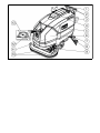 3
3
-
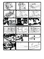 4
4
-
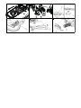 5
5
-
 6
6
-
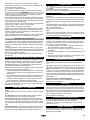 7
7
-
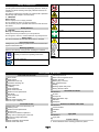 8
8
-
 9
9
-
 10
10
-
 11
11
-
 12
12
-
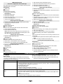 13
13
-
 14
14
-
 15
15
-
 16
16
-
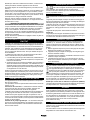 17
17
-
 18
18
-
 19
19
-
 20
20
-
 21
21
-
 22
22
-
 23
23
-
 24
24
-
 25
25
-
 26
26
-
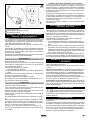 27
27
-
 28
28
-
 29
29
-
 30
30
-
 31
31
-
 32
32
-
 33
33
-
 34
34
-
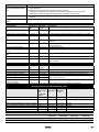 35
35
-
 36
36
-
 37
37
-
 38
38
-
 39
39
-
 40
40


K RCHER BD 70/75 W Classic Bp Vacuum Cleaner Manuel utilisateur
- Taper
- Manuel utilisateur
dans d''autres langues
Autres documents
-
Kärcher BD 43/25 C Bp Manuel utilisateur
-
Kärcher BD 50/50 C Bp Classic Scrubber Drier Manuel utilisateur
-
-
-
-
HTW ACUMULADOR AEROTERMICO VAW Manuel utilisateur
-
-
Windsor 30 Manuel utilisateur
-
HobartWelders TREK 180 Le manuel du propriétaire
-