Faber Diamante Isola 36 SS Guide d'installation
- Catégorie
- Hottes
- Taper
- Guide d'installation

Version 01/12 - Page 1
Diamante Isola
(LED electronic controls)
Island Mount Canopy Rangehood
• Installation Instructions
• Use and Care Information
READ AND SAVE THESE INSTRUCTIONS

Version 01/12 - Page 2
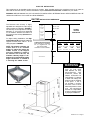
VENTING REQUIREMENTS
Determine which venting method is best for your application.
Ductwork can extend either through the wall or the roof.
The length of the ductwork and the number of elbows should
size of the ductwork should be uniform. Do not install two
elbows together. Use duct tape to seal all joints in the ductwork
around the cap.
Flexible ductwork is not recommended. Flexible ductwork
creates back pressure and air turbulence that greatly
reduces performance.
for exhaust duct before making cutouts. Do not cut a joist or
stud unless absolutely necessary. If a joist or stud must be
cut, then a supporting frame must be constructed.
FOR MORE SPECIFIC DUCTWORK INFORMATION, GO TO
PAGE 4.
WARNING - To Reduce The Risk Of Fire, Use Only Metal
Ductwork.
ELECTRICAL REQUIREMENTS
A 120 volt, 60 Hz AC-only electrical supply is required on a
separate 15 amp fused circuit. A time-delay fuse or circuit
breaker is recommended. The fuse must be sized per local
codes in accordance with the electrical rating of this unit as
CONNECTED WITH COPPER WIRE ONLY. Wire sizes must
conform to the requirements of the National Electrical Code,
ANSI/NFPA 70 - latest edition, and all local codes and ordi-
nances. Wire size and connections must conform with the
rating of the appliance. Copies of the standard listed above
may be obtained from:
National Fire Protection Association
Quincy, Massachusetts 02269
home.
other enclosed space.
ventilation air.
This appliance should be connected directly to the fused
nonmetallic sheathed copper cable. Allow some slack in the
cable so the appliance can be moved if servicing is ever neces-
at each end of the power supply cable (at the appliance and
at the junction box).
wall. A hole cut through wood must be sanded until smooth.
A hole through metal must have a grommet.
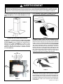
WARNING - TO REDUCE THE RISK OF FIRE OR ELECTRIC
SHOCK, do not use this fan with any solid-state speed
control device.
WARNING - TO REDUCE THE RISK OF FIRE, ELECTRI-
CAL SHOCK, OR INJURY TO PERSONS, OBSERVE THE
FOLLOWING: Use this unit only in the manner intended
by the manufacturer. If you have any questions, contact
the manufacturer.
Before servicing or cleaning unit, switch power off at
service panel and lock the service disconnecting means
to prevent power from being switched on accidentally.
When the service disconnecting means cannot be locked,
securely fasten a prominent warning device, such as a tag,
to the service panel.
CAUTION: For General Ventilating Use Only. Do Not Use To
Exhaust Hazardous or Explosive Materials and Vapors.
WARNING - TO REDUCE THE RISK OF FIRE, ELECTRI-
CAL SHOCK, OR INJURY TO PERSONS, OBSERVE THE
FOLLOWING: Installation Work And Electrical Wiring Must
Be Done By Qualied Person(s) In Accordance With All
Applicable Codes And Standards, Including Fire-Rated
Construction.
Sufcient air is needed for proper combustion and exhaust-
ing of gases through the ue (chimney) of fuel burning
equipment to prevent backdrafting. Follow the heating
equipment manufacturer's guideline and safety standards
such as those published by the National Fire Protection
Association (NFPA), and the American Society for Heating,
Refrigeration and Air Conditioning Engineers (ASHRAE),
and the local code authorities.
When cutting or drilling into wall or ceiling, do not damage
electrical wiring and other hidden utilities.
Ducted fans must always be vented to the outdoors.
WARNING
nonmetallic gaskets or other materials, DO NOT
use for grounding.
circuit. A fuse in the neutral or grounding circuit
could result in electrical shock.
doubt as to whether the rangehood is properly
grounded.
WARNING
For residential use only.
!
!
Cold Weather installations
An additional back draft damper should be installed to minimize
backward cold air ow and a nonmetallic thermal break should
be installed to minimize conduction of outside temperatures
as part of the vent system. The damper should be on the cold
air side of the thermal break. The break should be as close as
possible to where the vent system enters the heated portion
of the house.
CAUTION: To reduce risk of re and to properly exhaust air, be
sure to duct air outside - do not vent exhuast air into spaces within
walls or ceilings or into attics, crawl spaces or garages.

Version 01/12 - Page 3
RÈGLEMENTS D'ÉVACUATION
le toit.
Utilisez une longueur de tuyauterie minimale avec les moindres
du calfeutrage.
Utilisez un tuyau d'évacuation rigide lorsque possible.
Un tuyau exible égale deux fois plus qu'un tuyau rigide,
ce qui réduit la puissance d'évacuation.
RÈGLEMENTS D'ÉVACUATION ADDITIONELL - PAGE 11.
AVERTISSEMENT - Pour Ne Pas Risquer Un Feu, Utilisez
Seulement Les Matériaux Métalliques.
AVERTISSEMENT - POUR RÉDUIRE LE RISQUE
D'INCENDIE OU DE CHOC ELECTRIQUE, ne pas utiliser
ce ventilateur en conjonction avec un dispositif de réglage
de vitesse à semi-conducteurs.
AVERTISSEMENT – POUR MINIMISER LES RISQUES
D’INCENDIE, CHOC ÉLECTRIQUE OU DOMMAGES
CORPORELS, OBSERVER LES PRESCRIPTIONS
SUIVANTES: Suivez les recommandations du fabricant
et entre en communication avec lui pour toute
information.
Fermez le courant avant tout entretien et veillez a ce qu'il
reste fermé. Si on ne peut pas verrouiller le panneaux
du service électrique, afchez un avis de danger sur la
porte.
AVIS: Pour L'évacuation Générale - Veillez à Ne Pas
Evacuer Des Matériaux Ou Vapeurs Explosif.
AVERTISSEMENT – POUR MINIMISER LES RISQUES
D’INCENDIE, CHOC ÉLECTRIQUE OU DOMMAGES
CORPORELS, OBSERVER LES PRESCRIPTIONS
SUIVANTES: L'installation Et Le Raccordement Electrique
Doivent Se Faire Par Un Technicien Qualié Selon Tous
Les Codes Municipaux.
An d'obtenir un rendement maximal en ce qui a trait à la
combustion ainsi qu'à l'évacuation des gaz par la conduite
de cheminée, une bonne aération est nécessaire pour
tous les appareils à combustion. Suivez les conseils et
mesures de sécurité du fournisseur tels que ceux publiés
par l'Association Nationale de la Sauvegarde contre
l'Incendie et l'Association Américaine d'Ingénieurs de
Chauffage, Frigorifaction et Air Climatisé ainsi que les
codes municipaux.
En perçant un mur veillez à ne pas perforer un autre l
électrique.
Une ventilateur à évacuation extérieure doit être
raccordée à l'extérieur.
AVERTISSEMENT
pouces.
occasionner un feu.
FICHE TECHNIQUE ÉLECTRIQUE
recommande un coupe-circuit. La taille du fusible doit se
informations chez:
Quincy, Massachusetts 02269
Raccordez cet appareil directement au coupe-circuit avec un
occasionner un feu.
AVERTISSEMENT
Uniquement pour usage menager.
!
!
Installations pour régions à climat froid
On devrait installer un clapet antireux additionnel pour minimiser le
reux d'air froid, et incorporer un élément non métallique d'isolation
thermique pour minimiser la conduction de chaleur par l'intermédiaire
du conduit d'évacuation, de l'intérieur de la maison à l'extérieur.
Le clapet anti-reux doit être placé du côté air froid par rapport
à l'élément d'isolation thermique. L'isolant thermique doit être
aussi proche que possible de l'endroit où le système d'évacuation
s'introduit dans la partie
chauffée de la maison.

Version 01/12 - Page 4
TOOLS NEEDED FOR INSTALLATION
PARTS SUPPLIED FOR INSTALLATION
PARTS NEEDED FOR INSTALLATION
OPTIONAL ACCESSORIES AVAILABLE
High Ceiling Chimney Kit
Extends the island chimney for high
ceilings
part # HIGHDIAMIS - Stainless
*Ductless Conversion Kit
For non-vented installations only
* it is highly recommended that professional
style cooking always be vented to the
outside
part # DUCTDIAMIS - Stainless
Replacement Charcoal Filter
For non-vented installations only,
part # FILTER2
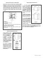
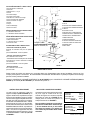
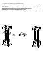
UNPACK THE RANGEHOOD
make sure that no mounting hardware or parts are missing. DO NOT REMOVE THE PLASTIC COVERING ON THE CHIMNEYS
AT THIS TIME! This plastic covering protects the chimney from scratches during installation.
For safe packaging, the entire chimney section of the hood is shipped assembled. It must be disassembled completely for
installation. Disassemble packaged chimney components by sliding apart the chimney covers (B and C in FIGURE 1). Remove
the LOWER CHIMNEY COVER (B) from the CHIMNEY SUPPORT (D) by removing the 2 philips screws on the outside bottom
of the chimney cover. Remove the UPPER CHIMNEY COVER (C) from the CHIMNEY SUPPORT (D) by removing the 2 philips
screws on the outside top of the chimney cover.
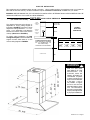
CALCULATE THE DUCTRUN LENGTH
The ductrun should not exceed 35 equivalent
feet if ducted with the required minimum of
ductwork by adding the equivalent feet in
FIGURE 2 for each piece of duct in the system.
An example is given in FIGURE 3.
For best results, use no more than three 90°
elbows. Make sure that there is a minimum
of 24" of straight duct between elbows if
more than one is used. Do not install two
elbows together. If you must elbow right
away, do it as far away from the hood's
exhaust opening as possible.
9 Feet Straight Duct
Wall Cap
Total System
FIGURE 3
3.0 feet
5.0 feet
12.0 feet
0.0 feet
Wall Cap
FIGURE 2
9.0 feet
10.0 feet
0.0 feet
19.0 feet
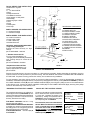
PREPARING TO ATTACH THE CHIMNEY
The rangehood attaches to the ceiling by a
metal support structure (D in FIGURE 1). This
support must be attached to the ceiling before
the canopy is attached. This structure must
FOR WOOD CEILINGS:
wood screws and washers.
FOR PLASTER OR SHEET ROCK CEILINGS:
If possible, the support must be attached to
the ceiling joists. If not, a supporting structure
behind the sheet rock must be built.
FOR WOOD SHELVES: Use items F, G, &
H in FIGURE 1.
FIGURE 1
RANGEHOOD COMPONENTS
A. CANOPY SECTION
B. LOWER CHIMNEY COVER
C. UPPER CHIMNEY COVER
D. CHIMNEY SUPPORT
E. CANOPY SCREWS
F.
G. WOOD SHELF WASHERS
H. WOOD SHELF NUTS
I. MOUNTING TEMPLATE
J.
K.
L
M. DAMPER
N
H
I
G
L
N
M
K
J
(N)

Version 01/12 - Page 5
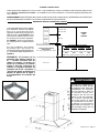
upper
chimney
cover
lower
chimney
cover
canopy
cabinet base
x = distance from hood to cooktop
(varies depending on installation)
min - 24”, suggested max - 30”
also consult cooktop
8 3/8” min
15 3/8” max
23
5/8”
3 3/16”
36”
FIGURE 4
DUCTED
DIMENSIONS
x
min & max ceiling height examples
x = 30"
min
max
x = 28"
min
max
x = 26"
min
max
x = 24"
min
max
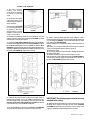
DUCTED INSTALLATION DIMENSIONS
(vented to the outside)
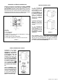
PLAN THE INSTALLATION
This rangehood can be installed as either ducted or ductless. When installed ductless, the rangehood vents out of grates on
either side of the lower chimney Ductless installations require a Ductless Conversion Kit, available from your dealer.
WARNING!
USED AND CAREFULLY CALCULATE ALL MEASUREMENTS.
WARNING
AND WEIGHT OF THIS
RANGEHOOD, THE
FIRMLY ATTACHED TO
THE CEILING. For plaster
or sheet rock ceilings, the
support must be attached
to the joists. If this is
not possible, a support
structure must be built
behind the plaster or sheet
rock. The manufacturer
assumes no responsibility
for injury or damage caused
by improper installations.
!
11 7/16"
FIGURE 5
The Diamante Isola chimney is highly
adjustable and designed to meet varying
ceiling heights as indicated in FIGURE 4.
The chimney can be adjusted for ceilings
on the distance between the bottom of
the hood and the cooktop (distance x in
FIGURE 4).
For higher ceiling installations, the High
Ceiling Chimney Kit includes an additional
ceiling heights in FIGURE 4.
NOTE: The chimney structure can
reduce down to a 27" minimum
height. To reduce the height, the
middle section of the support
structure (FIGURE 5) needs to
be removed. Out of the box, the
minimum chimney length is 32".
Subtract 5" from all minimum ceiling
height calculations in FIGURE 4
if removing the middle section.
26”
40 1/16"

Version 01/12 - Page 6
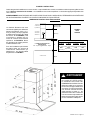
PLAN THE INSTALLATION
This rangehood can be installed as either ducted or ductless. When installed ductless, the rangehood vents out of grates on
either side of the lower chimney. Ductless installations require a Ductless Conversion Kit, available from your dealer.
WARNING!
USED AND CAREFULLY CALCULATE ALL MEASUREMENTS.
The ductless Diamante Isola chimney is
adjustable for varying ceiling heights as
indicated in FIGURE 6. The chimney can be
between the bottom of the hood and the
cooktop (distance x in FIGURE 6).
For higher ceiling installations, the High
Ceiling Chimney Kit includes an additional
various ceiling heights in FIGURE 6.
upper
chimney
cover
ductless
lower
chimney
cover
canopy
cabinet base
x = distance from hood to cooktop
(varies depending on installation)
min - 24”, suggested max - 30”
also consult cooktop
8 3/8” min
15
3/8” max
23
5/8”
36”
FIGURE 6
DUCTLESS
DIMENSIONS
x
min & max ceiling height examples
x = 30"
min
max
x = 28"
min
max
x = 26"
min
max
x = 24"
min
max
DUCTLESS INSTALLATION DIMENSIONS
(not vented to the outside)
12
3 3/16”
3 1/2”
WARNING
AND WEIGHT OF THIS
RANGEHOOD, THE
FIRMLY ATTACHED TO
THE CEILING. For plaster
or sheet rock ceilings, the
support must be attached
to the joists. If this is
not possible, a support
structure must be built
behind the plaster or sheet
rock. The manufacturer
assumes no responsibility
for injury or damage caused
by improper installations.
1
!
11 7/16"
40 1/16"

Version 01/12 - Page 7
.
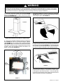
ATTACH THE SUPPORT
4. Determine and make necessary cuts for the ductwork. The duct
opening is shown on the mounting template (L in FIGURE 7). Install
ductwork before mounting the support.
FIGURE 7
1. Put a thick, protective
covering over cooktop,
set-in range or countertop
to protect from damage
or dirt.
2. Determine and clearly
mark with a pencil on the
ceiling where the rangehood
will be installed.
3. A template (L in FIGURE
7) for mounting the support
is supplied in the carton
with the support. Use this
template to mark holes for
support on the ceiling.
8. Install in previously drilled pilot holes in the ceiling the 4 bolts,
washers and nuts OR the wood screws from the parts bag depending
on your ceiling type (PAGE 4). Leave screw heads about ¹⁄4" away
from ceiling joists (A IN FIGURE 9).
9. Remove wiring box cover located on the top section of the chimney
support.
10. Install a UL or CSA listed strain relief in the wiring box so that the
screws can be tightened after the chimney support is
attached to the ceiling.
11. Lift chimney support into its nal position, feeding electrical wire
through the strain relief.
12. Position the chimney support so that the large end of the
keyhole slots are over the ceiling attachment bolts (B IN FIGURE 9).
Then push the chimney support so that the bolts are in the neck of
the slots. (C IN FIGURE 9) Tighten bolts securely.
IMPORTANT: The chimney support must be securely
attached to the ceiling.
13. Determine the desired length of the support structure and adjust
the length of the support by removing the four screws (indicated
in FIGURE 10) with a at head screwdriver. Once the length of the
support is determined, install and tighten the four screws.
6. Determine the proper location for the Power Supply Cable as
indicated on the template. Use a 1 1/4" Drill Bit to make this hole. Run
the Power Supply Cable. Use caulking to seal around the hole. DO
NOT turn on the power until installation is complete! A knockout
is provided at the top of the CHIMNEY SUPPORT .
7. For ducted installations, place the round DAMPER (N in FIGURE
1) into the exhaust opening of the rangehood and press down.
5. If using the High Ceiling Chimney Kit, remove the CHIMNEY
COVER from the CHIMNEY EXTENSION (A in FIGURE 8). Position
the CHIMNEY EXTENSION over the CHIMNEY SUPPORT (B in
FIGURE 8) so that the outside edges and the electrical holes line up.
Attach the CHIMNEY EXTENSION to the CHIMNEY SUPPORT using
the 4 bolts (C in FIGURE 8). Tighten bolts securely.
FIGURE 10
FIGURE 8
FIGURE 9
A. 1/4"
B
C

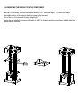
14. REMOVING THE MIDDLE TRESTLE COMPONENT
NOTE: The chimney structure can reduce down to a 27 " minimum height. To reduce the height,
the middle section of the support structure needs to be removed.
Out of the box, the minimum chimney length is 32 ".
Insure the the installation process outlined in the U&C is followed and there is sufficient stability with the
middle section removed.

Version 01/12 - Page 8
FIGURE 13
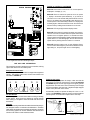
MAKE THE ELECTRICAL CONNECTION
Remove the cover from the eld wiring compartment. (SEE
FIGURE 11) DO NOT turn on the power until installation is
complete! Connect the Power Supply Cable to the rangehood.
Connect the Green (Green and Yellow) ground wire under the
Green grounding screw. Attach the White lead of the power
supply to the White lead of the rangehood with a twist-on type
wire connector. Attach the Black lead of the power supply
to the Black lead of the rangehood with a twist-on type wire
connector.
1. The UPPER CHIMNEY
COVER (C in FIGURE 13)
attaches to the top of the
support structure using two
screws provided (G in FIGURE
13). If using the High Ceiling
Chimney Kit, use the UPPER
CHIMNEY COVER supplied
with the kit. Slide up and
attach the UPPER CHIMNEY
COVER.
2. Attach the duct work to the
DAMPER (M in FIGURE 1).
Make sure to seal all joints with
duct tape to prevent leaks.
3. The LOWER CHIMNEY
COVER (B in FIGURE 13)
attaches using two screws
provided (G in FIGURE 13).
Install the LOWER CHIMNEY
COVER by sliding it up over
the support and the UPPER
CHIMNEY COVER.
For ductless installations, line up the DUCTLESS DIVERTER
EXTENSIONS HORIZONTAL (B in FIGURE 12) with the holes
in the LOWER CHIMNEY COVER (D in FIGURE 12) and snap
in the VENT GRIDS (C in FIGURE 12).
INSTALLING THE RANGEHOOD
A. Home power supply cable
B. Black wires
C. UL listed wire connectors
D.White wires
E. Green (or bare) ground wire from home power supply
connected to green ground screw
F. Range hood power supply cable
G.Range hood power supply cable connected to green
ground screw
FIGURE 11
Ductless installations require
a Ductless Conversion
Kit whose components are
pictured in FIGURE 12. Do
not use the DAMPER (M
in FIGURE 1) for ductless
installations. The LOWER
CHIMNEY COVER (B
in FIGURE 1) should be
discarded and replaced by
the new one with holes from
the Ductless Conversion Kit
(D in FIGURE 12).
As indicated in FIGURE
12, place the DUCTLESS
DIVERTER (A) over the
exhaust opening of the EASY
CUBE (E). Fit the DUCTLESS
DIVERTER EXTENSIONS
HORIZONTAL (B) into the
DIVERTER (A).
FIGURE 12
FOR DUCTLESS INSTALLATIONS

Version 01/12 - Page 9
For ductless installations, install the CHARCOAL FILTER (F in
FIGURE 12)
and locking into place. See FIGURE 16
WARNING
Two people must hold the canopy in place while the third person installs the screws that attach the canopy to the chimney.
The manufacturer assumes no responsibility for injury or damage caused by improper installations.
4. From below, attach the CANOPY SECTION (A in FIGURE
14) to the assembled chimney support using the four bolts
provided (F in FIGURE 14).
FIGURE 14
FIGURE 16
6.
turning the knob to the left so that the locking lever does not
(as in FIGURE 17). Insert the opposite
FIGURE 17
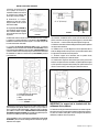
7. Turn the power supply on. Turn on blower and lights. If the
rangehood does not operate, check that the circuit breaker
is not tripped or the house fuse blown. If the unit still does
not operate, disconnect the power supply and check that the
wiring connections have been made properly.
5.
A in FIGURE 15
(A in FIGURE 15)
(B in FIGURE 15) by connecting the two black plastic pieces
using the four screws provided. Using the two longer screws
METAL FLANGE (C in FIGURE 15).
FIGURE 15
MAKE THE INTERNAL ELECTRICAL CONNECTIONS
A
!
A
B
C

Version 01/12 - Page 10
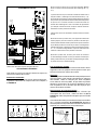
WIRING DIAGRAM
FIGURE 19
For Best Results
Start the rangehood several minutes before cooking to develop
after cooking is complete to clear all smoke and odors from
the kitchen.
Cleaning
hot detergent solution or washed in the dishwasher. Stainless
steel cleaner should be used on stainless rangehoods. Abrasives
USE AND CARE INFORMATION
This rangehood system is designed to remove smoke, cooking
vapors and odors from the cooktop area.
Rangehood Control Panel
The control panel is located on the front edge of the rangehood
canopy. The position and function of each control button are
indicated in FIGURE 18.
FIGURE 20
Replacing the Lamps
light switch is turned off. Remove the 2 screws (as indicated
in FIGURE 19) that hold the light support and gently pull the
support down from the hood. Remove the lamp from the light
support and replace with new lamp. Replace the light support
An alternative method to replace the lamps is to use a 1 1/4"
suction cup (FIGURE 20). Attach the suction cup to the bulb and
pull rmly down on the bulb and replace with a new lamp.
0 1 2 3 4 5 6 7 8 9
Creato da.
Rev :
Ver :
DOLCE CORRADO
Materiali: non deveno contenere Pb, Cr6+, Hg, PBB, pbde, ai sensi della direttiva 2002/95 CE
SCHEMA ELETTRICO M8-4V ATL FARETTI
Non rilevare quote dal grafico non app ortare modifiche senza l'autorizzazione d'ufficio progettazione
a termini di legge ci riserviamo la propr ieta' del presente disegno con divieto di riproduzione totale o parziale
Code :
Disegno N :
Data:
11.Nov.2010
436005191
H90_065
CN13
CN9
CN12
CN4
CN7
CN1
FASE
NEUTRO
COM
V1
V2
V3
V4
LUC.1 F.LUC.1 F.
LUC.1 N.
LUC.2 F.
LUC.2 N.
LINE IN
120Vac
60Hz ~
L
N
Y-G
WIRING BOX
Y-G
Faber ATL
1
2
3
4
5
7
6
1
2
3
4
BLU
BLK
L-B
RED
BLU
PNK
GRY
BRW
BLK
1
1
BLK
123
6 5 4
789
1 2 3
654
987
RED
M8 4V
120V ~
WHT
2
2
WHT
WHT
BRW
BRW
3
3
BRW
BLU
GRY
4
4
GRY
BLK
BLU
5
5
BLU
ORG
RED
6
6
RED
PNK
7
7
PNK
Y-G
VLT(ORG)
8
8
VLT(ORG)
RED(ORG)
9
9
RED(ORG)
RED
10
10
RED
VLT
11
11
VLT
12
12
TOROIDAL
TRANSFORMER
WHT
4
3
BLK
VLT
RED
2
1
BLK
RED
HALOGEN
LAMPS
ORG
2
1
ORG
4
3
RED
VLT
HALOGEN
LAMPS
HALOGEN
LAMPS
ORG
ORG
RED
HALOGEN
LAMPS
VLT
PRI.
SEC.
ELECTRONIC
TRNSFORMER
FIGURE 18 CONTROLS CONTINUED
Button A. Press button to turn fan on / off. Current speed is
displayed in C display (1, 2, 3)
Button B. Press to reduce fan speed to as low as speed
1, display C shows the speed selected (1, 2, 3). Hold for 3
seconds to turn on 30 minute delay feature which runs the
hood for 30 minutes and automatically shuts the hood off.
Current speed on 30 minute delay is shown in C display with
a blinking light to indicate 30 minute mode. Shut off the 30
minute mode by holding down the button for 3 seconds
Button C. LED single digit readout display screen
Button D. Press button to increase fan speed up to speed 3.
Hold for 3 seconds to activate intensive speed mode which
operates hood on highest speed for 10 minutes and then
returns to previous speed setting. Display C indicates intensive
speed with an "H" and blinking light. Shut off the intensive
speed mode by holding down the button for 3 seconds
Button E. Press the button to turn on and off lighting. Press
once to turn the dimmer light on, press twice to turn the normal
light setting on, and press again to turn off the lighting.
FIGURE 18
A
B
C
D
E

Version 01/12 - Page 11
January 4, 2016
FABER CONSUMER WARRANTY & SERVICE
All Faber products are warranted against any defect in materials or workmanship for the original purchaser
for a period of 1 year from the date of original purchase (requires proof of purchase). This warranty covers
labor and replacement parts. Faber, at its option, may repair or replace the product or components
necessary to restore the product to good working condition. To obtain warranty service, contact the dealer
from whom you purchased the range hood, or the local Faber distributor. If you cannot identify a local Faber
distributor, contact us at (508) 358-5353 for the name of a distributor in your area.
The following is not covered by Faber's warranty:
1. Service calls to correct the installation of your range hood, to instruct you how to use your range hood, to
replace or repair house fuses or to correct house wiring or plum
bing.
2. Service calls to repair or replace range hood light bulbs, fuses or filters. Those consumable parts are
excluded from warranty coverage.
3. Repairs when your range hood is used for other than normal, single-family household use.
4. Damage resulting from accident, alteration, misuse, abuse, fire, flood, acts of God, improper installation,
installation not in accordance with electrical or plumbing codes or Faber documentation, or use of products
not approved by Fabe
r.
5
. Replacement parts or repair labor costs for units operated outside the United States or Canada, including
any non-UL or C-UL approved Faber range hoo
ds.
6
. Repairs to the hood resulting from unauthorized modifications made to the range hood.
7. Expenses for travel and transportation for product service in remote locations and pickup and delivery
charges. Faber range hoods should be serviced in the hom
e.
THIS WARRANTY DOES NOT ALLOW RECOVERY OF INCIDENTAL OR CONSEQUENTIAL DAMAGES, INCLUDING, WITHOUT
LIMITATION, DIRECT, INDIRECT, INCIDENTAL, SPECIAL OR CONSEQUENTIAL DAMAGES, PERSONAL INJURY/WRONGFUL
DEATH OR LOST PROFITS FABER WARRANTY IS LIMITED TO THE ABOVE CONDITIONS AND TO THE WARRANTY PERIOD
SPECIFIED HEREIN AND IS EXCLUSIVE. EXCEPT AS EXPRESSLY SPECIFIED IN THIS AGREEMENT, FABER DISCLAIMS ALL
EXPRESS OR IMPLIED CONDITIONS, REPRESENTATIONS, AND WARRANTIES INCLUDING, WITHOUT LIMITATION, ANY
IMPLIED WARRANTIES OF MERCHANTABILITY OR FITNESS FOR A PARTICULAR PURPOSE
.
This warranty gives you specific legal rights that may vary from state to state.
Model#: ______________________________ Serial #: _____________________________

Version 01/12 - Page 12
OUTILS NÉCESSAIRES À L’INSTALLATION
PIÈCES FOURNIES POUR L’INSTALLATION
PIÈCES NÉCESSAIRES POUR L’INSTALLATION
ACCESSOIRES POUR L’INSTALLATION
Haut kit de cheminée de plafond
hauts
part # HIGHDIAMIS - Acier Inoxydable
• *Kit Pour Conversion Du Conduit
Pour installation sans conduit
part # DUCTDIAMIS - Acier Inoxydable
• Filtres au Charbon
Pour installation sans conduit
part # FILTER2
DÉBALLER LA HOTTE
(C de la FIGURE 1)(B de la
FIGURE 1) du TREILIS (D de la FIGURE 1)
CALCUL DE LONGUEUR DU CONDUIT
Calculer la longueur du conduit en ajoutant
FIGURE 2 pour
FIGURE 3.
Pour de meilleurs résultats, ne pas utiliser
plus de trois coudes de 90
o
. S’assurer qu’il
y ait un minimum de 24 po de conduit
droit entre les coudes si l’on utilise plus
d’un coude. Ne pas installer deux coudes
ensemble.
9 pi de conduit droit
Capuchon de mur
FIGURE 3
3,0 pi
5,0 pi
12,0 pi
0,0 pi
Capuchon de mur
FIGURE 2
9,0 pi
10,0 pi
0,0 pi
19,0 pi
INSTALLATION DU SUPPORT
(D de la FIGURE 1). Ce
cette structure supporte le poids de la hotte,
POUR LES PLAFONDS EN PLÂTRE OU EN
sinon, une structure supportante doit être
F, G, & H de
la FIGURE 1.
FIGURE 1
COMPONENTS DE LA HOTTE
A. HOTTE
B.
C.
D. TREILLIS
E. VIS POUR LA HOTTE
F.
G.
H.
I.
J.
K.
L
M. REGISTRE ROND
N
I
M
G
H
N
J
L
K
(N)

11 7/16"
FIGURE 5
26”
40 1/16"
Version 01/12 - Page 13
couvercle
cheminée
supérieure
couvercle
cheminée
inférieure
hotte
cabinet base
x = distance entre la hotte et la
table de cuisson
min - 24 po, suggested max - 30 po
8 3/8 po min
15 3/8 po max
23
5/8 po
3 3/16 po
36 po
FIGURE 4
AVEC
CONDUIT
x
min & max hauteurs de plafond
x = 30 po
min
8 pi 5
3/16 po
max
9 pi
3/16 po
x = 28 po
min
8 pi
3 3/16 po
max
8 pi
10 3/16 po
x = 26 po
min
8 pi
1 3/16 po
max
8 pi
8 3/16 po
x = 24 po
min
7 pi
11 3/16 po
max
8 pi
6 3/16 po
DIMENSIONS D’INSTALLATION AVEC CONDUIT
PLAN DE L’INSTALLATION
avec le Kit Pour Conversion Du Conduit.
votre marchand.
AVERTISSEMENT!
à CAUSE DE LA DIMENSION ET
DU POIDS DE CETTE HOTTE,
FERMEMENT AU PLAFOND.
en panneaux muraux secs,
solives. Si cela est impossible,
ou les panneaux muraux secs.
responsable des blessures ou
AVERTISSEMENT
!
entre 7 pi 11 3/16 po and 9 pi 3/16 po
(regardez la distance entre la hotte et la
table de cuisson - X en FIGURE 4). Cela
La FIGURE 4 illustre les dimensions
Isola.
de plafond inclut une structre de
FIGURE 4.
REMARQUE: La structure de la
cheminée peut réduire jusqu'à un
27 ".. Hauteur minimale Afin de
réduire la hauteur, la section du
milieu de la structure de soutien
(gure 5) doit être retiré Hors de
la boîte, la longueur minimale de
cheminée est de 32". Soustraire 5
"de tous les calculs au minimum la
hauteur du plafond sur la gure 4
si la suppression de la section du
milieu.

Version 01/12 - Page 14
PLAN DE L’INSTALLATION
avec le Kit Pour Conversion Du Conduit.
votre marchand.
AVERTISSEMENT!
couvercle
cheminée
supérieure
couvercle
cheminée
inférieure
hotte
cabinet base
x = distance entre la hotte et la
table de cuisson
min - 24 po, suggested max - 30 po
8 3/8 po min
15
3/8 po max
23
5/8 po
36 po
FIGURE 6
SANS
CONDUIT
x
min & max hauteurs de plafond
x = 30 po
min
8 pi
5 3/16 po
max
9 pi
3/16 po
x = 28 po
min
8 pi
3 3/16 po
max
8 pi
10 3/16 po
x = 26 po
min
8 pi 1 3/16 po
max
8 pi
8 3/16 po
x = 24 po
min
7 pi
11 3/16 po
max
8 pi
6 3/16 po
DIMENSIONS D’INSTALLATION SANS CONDUIT
12 1/2 po
3 3/16 po
3 1/2 po
à CAUSE DE LA DIMENSION ET
DU POIDS DE CETTE HOTTE,
FERMEMENT AU PLAFOND. Pour les
aux solives. Si cela est impossible,
panneaux muraux secs. Le fabricant
AVERTISSEMENT
hauteurs de plafond, entre 7 pi 11
3/16 po and 9 pi 3/16 po (regardez
la distance entre la hotte et la table
de cuisson - X en FIGURE 6). Cela
La FIGURE 6 illustre
de plafond inclut une structre de
de plafond sur le FIGURE 6.
!
1
11 7/16"
40 1/16"

Version 01/12 - Page 15
INSTALLATION DU SUPPORT
6. Déterminer l’emplacement approprié pour le câble d’alimentation, tel
qu’il est indiqué sur le gabarit. Utiliser un foret de 1 1/4 po pour faire un
trou et y passer le câble d’alimentation. Utiliser de la pâte à calfeutrer
pour sceller tout autour du trou. NE PAS mettre en circuit tant que
l’installation n’est pas complétée. Une pastille enfonçable est prévue
en haut de le
TREILLIS
pour le câble d’alimentation.
7. Pour installations avec conduit, placer le REGISTRE ROND (N de
la FIGURE 1) dans l'ouverture d'échappement de la hotte et appuyer
fortement sur le registre.
FIGURE 7
1. Placer un recouvrement épais
sur la plaque de cuisson, la
cuisinière encastrée ou le dessus
du comptoir pour protéger des
dommages et de la poussière.
2. Déterminer et marquer
clairement, à l’aide d’un crayon,
la ligne centrale sur le mur où la
hotte sera installée.
3. Un gabarit (L de la FIGURE 7)
pour installer le support est fourni
avec ce dernier. Utiliser ce gabarit
pour marquer les trous du support
au plafond.
4. Déterminer et faire toutes les coupes nécessaires pour les conduits.
L’ouverture du conduit est illustrée sur le gabarit (L de la FIGURE 7).
Installer les conduits avant de xer le support. Le conduit n'est pas dan
le centre exactement de le treillis.
5. Si en utilisant Le Haut Kit de Cheminée de plafond, enlever
COUVERCLE
CHEMINÉE
de la PROLONGATION DE CHEMIN´EE (A de la FIGURE 8). Placez la
PROLONGATION DE CHEMIN´EE au-dessus de
TREILLIS
(B de la FIGURE 8) de sorte
que les bords extérieurs et les trous électriques alignent. Attachez la PROLONGATION
DE CHEMIN´EE à la
TREILLIS
à l'aide des boulons (C de la FIGURE 8). Serrez les
boulons solidement.
FIGURE 10
FIGURE 8
FIGURE 9
B
C
8. Installer dans des trous forés précédemment pilotes dans le plafond
des 4 boulons, rondelles et écrous ou des vis à bois dans le sac des
pièces en fonction de votre type de plafond (page 4). Laisser les têtes
de vis environ ¹ / 4 "loin de solives de plafond (A dans la gure 9).
9. Retirez le couvercle du boîtier de câblage situé sur la partie supérieure
du support de la cheminée.
10. Installer une UL ou CSA allègement souche répertoriée dans la
boîte de câblage de telle sorte que les vis peuvent être serrées après
le support de la cheminée est xé au plafond.
11. Soulevez support de la cheminée dans sa position nale,
l'alimentation électrique par le câble de traction.
12. Positionnez le support de la cheminée pour que le gros bout de
la fentes sont plus les boulons de xation au plafond (B dans la gure
9). Puis poussez le support de la cheminée pour que les boulons sont
dans le cou des fentes. (C dans la gure 9) Serrer les boulons.
IMPORTANT: Le support de la cheminée doit être
solidement xé au plafond.
13. Déterminer la longueur désirée de la structure de soutien et ajuster
la longueur du support en enlevant les quatre vis (indiqué dans la gure
10) avec un tournevis à tête plate. Une fois la longueur de l'aide est
déterminé, installez et serrez les quatre vis.
A. Vis
A. Cadre rallonge de la cheminée
B. Le soutien de cheminée
C. Bolt
D. Insérez Captive leté

14. RETRAIT DU COMPOSANT DE TRESTE MOYEN
REMARQUE: La structure de la cheminée peut réduire jusqu'à une hauteur minimale de 27 " . Pour
réduire la hauteur, la section médiane de la structure de support doit être retiré.
Hors de la boîte, la longueur minimale de la cheminée est de 32 ".
Aucun problème du point de vue mécanique, la rigidité est garantie par le chevauchement des colonnes.

Version 01/12 - Page 16
Installations sans conduit
requièrent le Kit Pour
Conversion Du Conduit
(FIGURE 12). N'utilisez pas
le REGISTRE ROND (M
de la FIGURE 1) pour les
Installations sans conduit. Jeter
le COUVERCLE CHEMINÉE
INFÉRIEURE (B de la FIGURE
1) et replacer avec le couvercle
de cheminée inférieure avec
trous d’échappement d’air
dans le Kit Pour Conversion
Du Conduit (D de la FIGURE
12).
Illustré à la FIGURE 12, mettre
le DUCTLESS DIVERTER (A)
dans l'ouverture d'échappement
de la EASY CUBE (E). Mettre
le DUCTLESS DIVERTER
EXTENSION HORIZONTAL
(B) dans le DIVERTER (A).
FIGURE 12
FIGURE 13
BRANCHER LE CÂBLE D'ALIMENTATION
Retirer le couvercle du compartiment de câblage. (FIGURE
11) NE PAS mettre en circuit tant que l’installation n’est
pas complétée. Brancher le câble d’alimentation sur la hotte.
Brancher le l de mise à la terre vert (jaune et vert) sous la vis
de mise à la terre verte. Relier le l blanc du câble d’alimentation
au l blanc de la hotte avec une cosse. Relier le l noir du câble
d’alimentation au l noir de la hotte avec une cosse.
INSTALLATIONS SANS CONDUIT
1. Le COUVERCLE
CHEMINÉE SUPÉRIEURE
(C de la FIGURE 13) se xe
avec les deux vis fournies
(G de la FIGURE 13).
Si
en utilisant Le Haut Kit
de Cheminée de plafond,
utilisez
Le COUVERCLE
CHEMINÉE SUPÉRIEURE
avec le kit. Fixer le
COUVERCLE CHEMINÉE
SUPÉRIEURE.
2. Brancher le conduit sur le
REGISTRE ROND (M de la
FIGURE 1) et sceller toutes
les connexions avec du ruban
à conduit.
3. Le COUVERCLE
CHEMINÉE INFÉRIEURE
(B de la FIGURE 13) se xe
avec les deux vis fournies (G
de la FIGURE 13). Fixer le
COUVERCLE CHEMINÉE
INFÉRIEURE.
Pour installations sans conduit, aligner les DUCTLESS
DIVERTER EXTENSIONS HORIZONTAL (B de la FIGURE
12) avec les trous d’échappement d’air dans COUVERCLE
CHEMINÉE INFÉRIEURE (D de la FIGURE 12) et installer
les VENT GRIDS (C de la FIGURE 12).
INSTALLATION DU HOTTE
A. Accueil câble d'alimentation
B. ls noirs
C. UL connecteurs
D. Les ls blancs
E. Green (ou nu) le l de terre de l'alimentation à domicile
connecté à vis de terre verte
F. Range capuche câble d'alimentation
G. Hood câble d'alimentation relié à la vis de terre verte
FIGURE 11

Version 01/12 - Page 17
Pour installations sans conduit, installer le FILTRE AU
(F de la FIGURE 12). Voyez FIGURE 16
AVERTISSEMENT
LA HOTTE.
4.
(F de la FIGURE 14) la HOTTE (A de la FIGURE 14) au treillis
FIGURE 14
FIGURE 16
6.
(de la FIGURE
17)
bouton et le tourner vers la gauche (sens antihoraire) de telle
sorte que le levier de verrouillage ne fasse pas saillie hors du
7.
correctement.
5. Connecter le CONNECTEUR DES COMMANDES (A de la
FIGURE 15)
(A de la FIGURE 15)
plastique noire (B de la FIGURE 15) en reliant les deux
(C de la FIGURE 15).
FIGURE 15
CONNECTER LES CONNECTEURS INTERNE
FIGURE 17
!
A
A
B
C

Version 01/12 - Page 18
•Cette hotte utilise des ampoules halogènes de 20 W.
DIAGRAMME DE CÂBLAGE
FIGURE 19
Pour de meilleurs résultats
Mettre la hotte en circuit avant de commencer la cuisson. Laisser
l’appareil fonctionner quelques minutes après la cuisson pour
éliminer la fumée et les odeurs de la cuisine.
Nettoyage
Les ltres à graisse en métal devraient être nettoyés fréquemment
dans une solution d’eau chaude et de détergent ou mettre au
lave-vaisselle. Utiliser un nettoyant pour l’acier inoxydable
sur les hottes en acier inoxydable. Ne pas utiliser de produits
abrasifs ou de récurants, car ils peuvent égratigner le ni en
acier inoxydable et ils ne devraient pas être employés pour
nettoyer les surfaces de nition.
Remplacement de la lumière halogène
Avant d’essayer de remplacer les ampoules, s’assurer que
l’interrupteur soit hors circuit. Retirer les deux vis (de la
FIGURE 19). Retirer l’ampoule et la remplacer par une nouvelle
ampoule.
Une méthode alternative pour substituer les lampes est d'utiliser
des 1 1/4"tasses d'aspiration (de la FIGURE 20). Attachez la
tasse d'aspiration à l'ampoule et tirez fermement vers le bas sur
l'ampoule et la substituez avec une nouvelle lampe.
UTILISATION ET ENTRETIEN
Cette hotte est conçue pour enlever la fumée, les vapeurs de
cuisson et les odeurs de la cuisine.
Panneau de commandes
Le panneau de commandes est situé sur le devant de la hotte.
La position et la fonction de chaque bouton sont indiquées à
la FIGURE 18.
FIGURE 20
FIGURE 18
0 1 2 3 4 5 6 7 8 9
Creato da.
Rev :
Ver :
DOLCE CORRADO
Materiali: non deveno contenere Pb, Cr6+, Hg, PBB, pbde, ai sensi della direttiva 2002/95 CE
SCHEMA ELETTRICO M8-4V ATL FARETTI
Non rilevare quote dal grafico non app ortare modifiche senza l'autorizzazione d'ufficio progettazione
a termini di legge ci riserviamo la propr ieta' del presente disegno con divieto di riproduzione totale o parziale
Code :
Disegno N :
Data:
11.Nov.2010
436005191
H90_065
CN13
CN9
CN12
CN4
CN7
CN1
FASE
NEUTRO
COM
V1
V2
V3
V4
LUC.1 F.LUC.1 F.
LUC.1 N.
LUC.2 F.
LUC.2 N.
LINE IN
120Vac
60Hz ~
L
N
Y-G
WIRING BOX
Y-G
Faber ATL
1
2
3
4
5
7
6
1
2
3
4
BLU
BLK
L-B
RED
BLU
PNK
GRY
BRW
BLK
1
1
BLK
123
6 5 4
789
1 2 3
654
987
RED
M8 4V
120V ~
WHT
2
2
WHT
WHT
BRW
BRW
3
3
BRW
BLU
GRY
4
4
GRY
BLK
BLU
5
5
BLU
ORG
RED
6
6
RED
PNK
7
7
PNK
Y-G
VLT(ORG)
8
8
VLT(ORG)
RED(ORG)
9
9
RED(ORG)
RED
10
10
RED
VLT
11
11
VLT
12
12
TOROIDAL
TRANSFORMER
WHT
4
3
BLK
VLT
RED
2
1
BLK
RED
HALOGEN
LAMPS
ORG
2
1
ORG
4
3
RED
VLT
HALOGEN
LAMPS
HALOGEN
LAMPS
ORG
ORG
RED
HALOGEN
LAMPS
VLT
PRI.
SEC.
ELECTRONIC
TRNSFORMER
B
C
D
Bouton-poussoir du bouton A. pour tourner le ventilateur "Marche/
Arrêt". La vitesse courante est montrée dans l'afchage de C (1,
2, 3)
La presse du bouton B. pour ramener la vitesse de l'hélice aussi à
bas que la vitesse 1, l'afchage C montre la vitesse choisie (1, 2, 3).
Tenez pendant 3 secondes pour allumer le dispositif minute du retard
30 qui court le capot pendant 30 minutes et ferme automatiquement
le capot au loin. La vitesse courante sur le retard 30 minute est
montrée dans l'afchage de C avec une lumière de clignotement
pour indiquer le mode 30 minute. Coupez le mode 30 minute en
maintenant le bouton pendant 3 secondes.
C.Boutonnez l'écran de visualisation simple de lecture de chiffre
de LED
Boutonnez le bouton-poussoir de D. pour augmenter la vitesse de
l'hélice jusqu'à la prise de la vitesse 3. pendant 3 secondes pour
activer le mode intensif de vitesse qui actionne le capot sur la vitesse
la plus élevée pendant 10 minutes et puis revient à l'arrangement
précédent de vitesse. L'afchage C indique la vitesse intensive avec
un " ; H" ; et lumière de clignotement. Coupez le mode intensif de
vitesse en maintenant le bouton pendant 3 secondes
Boutonnez la presse d' E. le bouton pour tourner en marche et
en arrêt l'allumage. Pressez une fois pour allumer la lumière plus
faible, pressez deux fois pour allumer l'arrangement léger normal,
et pressez encore pour arrêter l'éclairage.
A
E
La page est en cours de chargement...
La page est en cours de chargement...
La page est en cours de chargement...
La page est en cours de chargement...
-
 1
1
-
 2
2
-
 3
3
-
 4
4
-
 5
5
-
 6
6
-
 7
7
-
 8
8
-
 9
9
-
 10
10
-
 11
11
-
 12
12
-
 13
13
-
 14
14
-
 15
15
-
 16
16
-
 17
17
-
 18
18
-
 19
19
-
 20
20
-
 21
21
-
 22
22
-
 23
23
-
 24
24


Faber Diamante Isola 36 SS Guide d'installation
- Catégorie
- Hottes
- Taper
- Guide d'installation