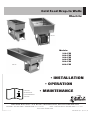
Alto-Shaam 200-CW Installation Operation & Maintenance
- Catégorie
- Chauffe-plats
- Taper
- Installation Operation & Maintenance

W164 N9221 Water Street • P.O. Box 450 • Menomonee Falls, Wisconsin 53052-0450 USA
PHONE: 262.251.3800 • 800.558.8744
USA/CANADA
FAX: 262.251.7067 • 800.329.8744
U.S.A. ONLY
www.alto-shaam.com
PRINTED IN U .S . A .
MN-36033 (REV. 0) • 07/14
s).34!,,!4)/.
s/0%2!4)/.
s-!).4%.!.#%
-odels:
#7
#7
#7
#7
#7
#7
100-CW
300-CW
500-CW
Consult
instructions
for installation
and use.
#OLD&OOD$ROP)N7ELLS
%LECTRIC

ÎÈäÎÎÊ,iÛ°Êä®ÊUÊ`Ê`ÊÀ«Ê7iÊ"«iÀ>ÌÊEÊ>ÀiÊ>Õ>
Delivery ..................................1
Unpacking................................1
Safety Procedures and Precautions ............2
Installation
Installation Requirements .................. 3
Installation and Leveling ...................4
Options & Accessories ....................5
Dimensions.............................5
Rough Cut Openings ..................... 8
Product/Pan Capacity ....................8
Louver and Vent Housing Instructions ........ 9
Rotation of Compressor Instructions ........ 10
Electrical Specifications .................. 11
Electrical Connection .................... 11
Plumbing Connection .................... 11
Installation Checklist .................... 12
Operating Instructions
Operating Instructions ................... 13
Care and Cleaning
Cleaning and Preventative Maintenance...... 14
Protecting Stainless Steel Surfaces ......... 14
Cleaning Agents ........................ 14
Cleaning Materials ...................... 14
Care and Cleaning ...................... 15
Sanitation ............................. 16
Preventative Maintenance................. 17
Service
Trouble Shooting ....................... 18
Service Parts - Exterior .................. 19
Wire Diagrams
Always refer to the wire diagram(s) included with
the unit for most current version.
Warranty
Transportation Damage and Claims ..Back Cover
Limited Warranty ................Back Cover

ÎÈäÎÎÊ,iÛ°Êä®ÊUÊ`Ê`ÊÀ«Ê7iÊ"«iÀ>ÌÊEÊ>ÀiÊ>Õ>ÊUÊ£
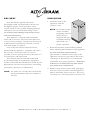
DELIVERY
This Alto-Shaam appliance has been
thoroughly tested and inspected to ensure only
the highest quality unit is provided. Upon
receipt, check for any possible shipping damage
and report it at once to the delivering carrier.
See Transportation Damage and Claims section
located in this manual.
This appliance, complete with unattached
items and accessories, may have been delivered
in one or more packages. Check to ensure that all
standard items and options have been received
with each model as ordered.
Save all the information and instructions
packed with the appliance. Complete and return
the warranty card to the factory as soon as
possible to ensure prompt service in the event of a
warranty parts and labor claim.
This manual must be read and understood
by all people using or installing the equipment
model. Contact the Alto-Shaam Tech Team Service
Department if you have any questions concerning
installation, operation, or maintenance.
NOTE: All claims for warranty must include the
full model number and serial number of
the unit.
UNPACKING
1. Carefully remove the
appliance from the
carton or crate.
NOTE: Do not discard the
carton and other
packaging material
until you have
inspected the unit
for hidden damage
and tested it for
proper operation.
2. Read all instructions in this manual carefully
before initiating the installation of this appliance.
DO NOT DISCARD THIS MANUAL.
This manual is considered to be part of the
appliance and is to be provided to the owner
or manager of the business or to the person
responsible for training operators. Additional
manuals are available from the Alto-Shaam
Tech Team Service Department.
3. Remove all protective plastic film, packaging
materials, and accessories from the appliance
before connecting electrical power. Store any
accessories in a convenient place for future use.
®
®

ÎÈäÎÎÊ,iÛ°Êä®ÊUÊ`Ê`ÊÀ«Ê7iÊ"«iÀ>ÌÊEÊ>ÀiÊ>Õ>ÊUÊÓ
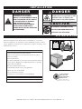
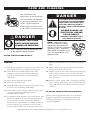
CAUTION
Used to indicate the presence of a hazard that
can or will cause minor personal injury, property
damage, or a potential unsafe practice if the
warning included with this symbol is ignored.
CAUTION
Used to indicate the presence of a
hazard that can or will cause minor or
moderate personal injury or property
damage if the warning included with
this symbol is ignored.
DANGER
Used to indicate the presence of
a hazard that WILL cause severe
personal injury, death, or substantial
property damage if the warning
included with this symbol is ignored.
WARNING
Used to indicate the presence of
a hazard that CAN cause personal
injury, possible death, or major
property damage if the warning
included with this symbol is ignored.
1. This appliance is intended to cook, hold
or process foods for the purpose of human
consumption. No other use for this appliance is
authorized or recommended.
2. This appliance is intended for use in commercial
establishments where all operators are
familiar with the purpose, limitations, and
associated hazards of this appliance. Operating
instructions and warnings must be read and
understood by all operators and users.
3. Any troubleshooting guides, component views,
and parts lists included in this manual are for
general reference only and are intended for use
by qualified technical personnel.
4. This manual should be considered a permanent
part of this appliance. This manual and all
supplied instructions, diagrams, schematics,
parts lists, notices, and labels must remain with
the appliance if the item is sold or moved to
another location.
NOTE: Used to notify personnel of
installation, operation, or
maintenance information that is
important but not hazard related.
SAFETY PROCEDURES
AND PRECAUTIONS
Knowledge of proper procedures is essential to the
safe operation of electrically and/or gas energized
equipment. In accordance with generally accepted
product safety labeling guidelines for potential
hazards, the following signal words and symbols
may be used throughout this manual.
Used to indicate that referral to
operating instructions is a mandatory
action. If not followed the operator
could suffer personal injury.
Used to indicate that referral to
operating instructions is recommended
to understand operation of equipment.
NOTE
For equipment delivered for use
in any location regulated by the
following directive:
DO NOT DISPOSE OF ELECTRICAL
OR ELECTRONIC EQUIPMENT WITH
OTHER MUNICIPAL WASTE.

ÎÈäÎÎÊ,iÛ°Êä®ÊUÊ`Ê`ÊÀ«Ê7iÊ"«iÀ>ÌÊEÊ>ÀiÊ>Õ>ÊUÊÎ
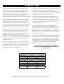
INSTALLATI ON
S I T E INSTALLATI ON
The Alto-Shaam Cold Well must be installed in a location
that will permit it to function for its intended purpose and to
allow adequate clearance for ventilation, proper cleaning, and
maintenance access.
®
DANGER
IMPROPER INSTALLATION,
ALTERATION, ADJUSTMENT,
SERVICE, OR MAINTENANCE COULD
RESULT IN SEVERE INJURY, DEATH,
OR CAUSE PROPERTY DAMAGE.
READ THE INSTALLATION,
OPERATING AND MAINTENANCE
INSTRUCTIONS THOROUGHLY
BEFORE INSTALLING OR SERVICING
THIS EQUIPMENT.
CAUTION
TO PREVENT PERSONAL INJURY,
USE CAUTION WHEN MOVING OR
LEVELING THIS APPLIANCE.
DANGER
DO NOT store or use gasoline or other
fl ammable vapors or liquids in the
vicinity of this or any other appliance.
inStaLLation rEQuirEMEntS
Counter top material must be water resistant.
Distance of 3/4" (19mm) or more between top rims of wells to
ensure easy cleaning.
Must be installed level.
Must not be installed in any area where it may be directly affected
by steam, grease, dripping water, high temperatures, or any other
severely adverse conditions.
Must not be installed under a hood.
Avoid installation under a 4-way ceiling diffuser.
Outdoor use is not recommended.
Drain or catch basin is required.
LED lighting is recommended for overhead lighting
cLEarancE rEQuirEMEntS
4" (102mm) in front of dual air movement louver
ELEctricaL
VOLTAGE PHASE CYCLE/HZ AMPS KW PLUG CONFIG.
115 1 60 5.0 .6 NEMA 5-15P
15A-125V PLUG
9' (229mm) LONG CORD
5-Year Limited
Warranty on
self-contained
compressor
Effective from date of
shipment. (EXCLUDES LABOR)

ÎÈäÎÎÊ,iÛ°Êä®ÊUÊ`Ê`ÊÀ«Ê7iÊ"«iÀ>ÌÊEÊ>ÀiÊ>Õ>ÊUÊ{
S I T E INSTALLATI ON
1. The cold well must be installed on a stable and
level surface - free of vibration and suitably
strong enough to support the combined weights
of the unit plus the maximum product load
weight.
2. DO NOT install this appliance in any area
where it may be affected by any adverse
conditions. Avoid placing the unit in direct
sunlight, near heat generating equipment
such as ovens, ranges, heaters, fryers, steam
kettles, dripping water, high temperatures, or
any other severely adverse conditions. Avoid
locating in an unheated room or where the room
temperature may drop below 55°F (13°C) or
above 86°F (30°C).
3. Once the drop in unit is installed into the
counter it can be secured to the counter top by
using the brackets supplied.
a. Locate square openings on exterior body of
drop unit. Insert securing bracket as shown.
Tighten screw to anchor the unit tightly to
cabinet top.
b. Seal top flange to the counter top by using
food grade silicone sealant.
4. The air cooled self contained units require
a sufficient amount of cool clean air. The
mechanical housing (except on 100-CW
appliances) can be rotated so that the condenser
intake air can be in direct line with the cabinet
fresh air opening.
a. Loosen wings nuts located under cold pan
body and rotate carriage to desired location.
b. Tighten wing nuts when rotation is complete.
c. Loosen wing nuts on each side of condenser
shroud and extend to fresh air opening.
d. Tighten wing nuts on each side of condenser
shroud.
Cross ventilation in the cabinet is recommended
to maintain ambient temperature 86°F (30°C) or
less.
5. DO NOT store or use any flammable liquids or
allow flammable vapors in the vicinity of this
appliance or any other appliance.
6. This appliance must be kept free and clear of
any combustible materials.
LEVELING
The cold well
should be
leveled before
the electrical supply is
connected. Level the appliance from side-
to-side and front-to-back with the use of a spirit
level.
NOTE
It is important to apply a food grade silicone
underneath the decor flange to seal flange to
the counter top.
INSTALLATI ON

ÎÈäÎÎÊ,iÛ°Êä®ÊUÊ`Ê`ÊÀ«Ê7iÊ"«iÀ>ÌÊEÊ>ÀiÊ>Õ>ÊUÊx
INSTALLATI ON
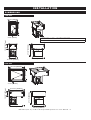
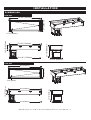
18-1/2" (470mm)
27" (686mm)
2-1/2" (64mm)
10-1/2" (267mm)
16-7/16" (418mm)
25-1/8" (638mm)
27-1/2" (699mm)
100-CW
31-7/16" (799mm)
10-1/2" (267mm)
29-3/8" (746mm)
25-1/8" (638mm)
2-1/2" (64mm)
27" (686mm)
31-7/16 (799mm)
27-1/2" (699mm)
D I M E NSI ONS
200-CW
OPTIONS AND ACCESSORIES
12" (305mm) Half Size / Third-Size Divider Bars 1014395

ÎÈäÎÎÊ,iÛ°Êä®ÊUÊ`Ê`ÊÀ«Ê7iÊ"«iÀ>ÌÊEÊ>ÀiÊ>Õ>ÊUÊÈ
INSTALLATI ON
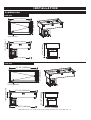
D I M E NSI ONS
44-1/4" (1124mm)
27" (686mm)
2-1/2" (64mm)
44-1/4" (1124mm)
10-1/2" (267mm)
42-1/4" (1072mm)
25-1/8" (638mm)
27-1/2" (699mm)
300-CW
57-1/4" (1453mm)
27" (686mm)
2-1/2" (64mm)
10-1/2" (267mm)
57-1/4" (1453mm)
55-3/16" (1401mm)
25-1/8" (638mm)
27-1/2" (699mm)
400-CW

ÎÈäÎÎÊ,iÛ°Êä®ÊUÊ`Ê`ÊÀ«Ê7iÊ"«iÀ>ÌÊEÊ>ÀiÊ>Õ>ÊUÊÇ
INSTALLATI ON
2-1/2" (64mm)
27" (686mm)
10-1/2" (267mm)
70-1/8" (1781mm)
68-1/16" (1729mm)
25-1/8" (638mm)
70-1/8" (1781mm)
27-1/2" (699mm)
D I M E NSI ONS
600-CW
500-CW
83" (2108mm)
27" (686mm)
2-1/2" (64mm)
10-1/2" (267mm)
83" (2108mm)
25-1/8" (638mm)
81" (2056mm)
27-1/2" (699mm)

ÎÈäÎÎÊ,iÛ°Êä®ÊUÊ`Ê`ÊÀ«Ê7iÊ"«iÀ>ÌÊEÊ>ÀiÊ>Õ>ÊUÊn
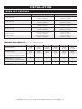
100-CW 200-CW 300-CW 400-CW 500-CW 600-CW
Maximum Capacity 36 lb
(16.3 kg)
72 lb
(32.6 kg)
108 lb
(48.9 kg)
144 lb
(65.2 kg)
180 lb
(81.5 kg)
216 lb
(97.8 kg)
Maximum Volume 22 qt
(21 L)
44 qt
(42 L)
66 qt
(62 L)
88 qt
(84 L)
110 qt
(105 L)
132 qt
(126 L)
Full-Size Pans* - 12" x 20" x 6"
GN 1/1 (325mm x 530mm x 176mm)
1 2 3 4 5 6
Half-Size Pans* - 12" x 10" x 6"
GN 1/2 (325mm x 265mm x 176mm)
2 4 6 8 10 12
Third-Size Pans* - 12" x 6" x 6"
GN 1/3 (325mm x 176mm x 176mm)
3 6 9 12 15 18
* WILL ALSO ACCEPT 2-1/2" (65mm) DEEP PANS AND 4" (102mm) DEEP PANS
product\pan capacity (BASED ON 6" [176mm] DEEP PANS)
INSTALLATI ON
ROUGH CUT OPE N I N G S
MODEL CO U NTE R TOP OPEN I N G AI R LOUVER OPENING
100-CW ONE PAN
16-7/8" L x 25-1/2" W
(429mm x 648mm)
21" H x 16" W
(533mm x 406mm)
200-CW
TWO PAN
29-7/8" L x 25-1/2" W
(759mm x 648mm)
21" H x 16" W
(533mm x 406mm)
300-CW
THREE PAN
42-3/4" L x 25-1/2" W
(1085mm x 648mm)
21" H x 16" W
(533mm x 406mm)
400-CW
FOUR PAN
55-5/8" L x 25-1/2" W
(572mm x 648mm)
21" H x 16" W
(533mm x 406mm)
500-CW
FIVE PAN
68-1/2" L x 25-1/2" W
(1740mm x 648mm)
21" H x 16" W
(533mm x 406mm)
600-CW
SIX PAN
81-1/2" L x 25-1/2" W
(2070mm x 648mm)
21" H x 16" W
(533mm x 406mm)

ÎÈäÎÎÊ,iÛ°Êä®ÊUÊ`Ê`ÊÀ«Ê7iÊ"«iÀ>ÌÊEÊ>ÀiÊ>Õ>ÊUÊ
INSTALLATI ON
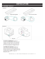
PLACEMENT DETAILS
Retractable vent housing must
be extended out to engage
louver panel then locked down
Air exhaust
Air intake
Compressor cage
MODEL A B C D F
100-CW ONE PAN
18-1/2"
(470mm)
27"
(686mm)
16-7/8"
(429mm)
25-1/2"
(648mm)
1-1/2" – 7-1/2"
(38mm – 191mm)
200-CW
TWO PAN
31-7/16"
(799mm)
27"
(686mm)
29-7/8"
(759mm)
25-1/2"
(648mm)
1-1/2" – 7-1/2"
(38mm – 191mm)
300-CW
THREE PAN
44-1/4"
(1124mm)
27"
(686mm)
42-3/4"
(1085mm)
25-1/2"
(648mm)
1-1/2" – 7-1/2"
(38mm – 191mm)
400-CW
FOUR PAN
57-1/4"
(1453mm)
27"
(686mm)
55-5/8"
(572mm)
25-1/2"
(648mm)
1-1/2" – 7-1/2"
(38mm – 191mm)
500-CW
FIVE PAN
70-1/8"
(1781mm)
27"
(686mm)
68-1/2"
(1740mm)
25-1/2"
(648mm)
1-1/2" – 7-1/2"
(38mm – 191mm)
600-CW
SIX PAN
83"
(2108mm)
27"
(686mm)
81-1/2"
(2070mm)
25-1/2"
(648mm)
1-1/2" – 7-1/2"
(38mm – 191mm)
Louver panel
Dim "F" +4"
(critical)

ÎÈäÎÎÊ,iÛ°Êä®ÊUÊ`Ê`ÊÀ«Ê7iÊ"«iÀ>ÌÊEÊ>ÀiÊ>Õ>ÊUÊ£ä
INSTALLATI ON
PLACEMENT DETAILS
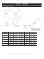
To roTaTe compressor (illustration 1),
loosen 4 mounting bolts on the top of the
compressor cage 1 and 1/2 turns. Hold
compressor cage by the frame and rotate
90° to desired position. Retighten bolts.
To exTend venT housing (illustration 2),
remove louver and loosen wing nuts
located on the side of housing. Extend the
housing until it engages with the louvered
opening. Finger tighten wing nuts.
Reinstall louver.
Side of unit bolt pattern
Wing Nuts
Rear of unit bolt pattern
Illustration 1
Illustration 2

ÎÈäÎÎÊ,iÛ°Êä®ÊUÊ`Ê`ÊÀ«Ê7iÊ"«iÀ>ÌÊEÊ>ÀiÊ>Õ>ÊUÊ££
INSTALLATI ON
E L ECTRICAL CONNECT I ON
1. Drains must be plumbed to all applicable local code requirements.
2. Moisture collecting from improper drainage can create a slippery surface on the
floor and a hazard to employees.
PLU M BIN G CONNECT I ON
inStaLLation rEQuirEMEntS
Counter top material must be water resistant.
Distance of 3/4" (19mm) or more between top rims of wells to
ensure easy cleaning.
Must be installed level.
Must not be installed in any area where it may be directly affected
by steam, grease, dripping water, high temperatures, or any other
severely adverse conditions.
Must not be installed under a hood.
Avoid installation under a 4-way ceiling diffuser.
Outdoor use is not recommended.
Drain or catch basin is required.
LED lighting is recommended for overhead lighting
cLEarancE rEQuirEMEntS
4" (102mm) in front of dual air movement louver
ELEctricaL
VOLTAGE PHASE CYCLE/HZ AMPS
KW PLUG CONFIG.
115 1 60 5.0 .6
NEMA 5-15P
15A-125V PLUG
9' (229
mm
) LONG CORD
1. An identification tag is permanently mounted
on the front control panel of the appliance.
2. This appliance is equipped with a three-prong
grounding plug. For your protection against
shock hazard this appliance should be plugged
directly into a properly grounded three-prong
receptacle. Do not cut or remove the grounding
prong from this plug. Plug the unit into a
properly grounded receptacle ONLY, positioning
the unit so that the plug is easily accessible in
case of an emergency. Arcing will occur when
connecting or disconnecting the unit unless all
controls are in the “OFF” position.
3. Proper receptacle or outlet configuration or
permanent wiring for this unit must be installed
by a licensed electrician in accordance with
applicable local electrical codes.
4. It is important that a voltage reading be made
at the compressor motor electrical connections
while the unit is in operation to verify that the
correct voltage required by the appliance is being
supplied. Low or high voltage can detrimentally
affect operation and void the warranty.
5. The cold well unit should have its own dedicated
line. Condensing units are designed to operate
with a voltage fluctuation of plus or minus 10%
of the voltage indicated on the unit data tag. Burn
out of a condensing unit due to exceeding voltage
limits will void the warranty.
DANGER
ENSURE POWER SOURCE
MATCHES VOLTAGE IDENTIFIED
ON APPLIANCE RATING TAG.
DANGER
ELECTRICAL CONNECTIONS MUST
BE MADE BY A QUALIFIED SERVICE
TECHNICIAN IN ACCORDANCE WITH
APPLICABLE ELECTRICAL CODES.
DANGER
To avoid electrical shock, this
appliance MUST be adequately
grounded in accordance with local
electrical codes or, in the absence of
local codes, with the current edition
of the National Electrical Code ANSI/
NFPA No. 70. In Canada, all electrical
connections are to be made in
accordance with CSA C22.1, Canadian
Electrical Code Part 1 or local codes.

ÎÈäÎÎÊ,iÛ°Êä®ÊUÊ`Ê`ÊÀ«Ê7iÊ"«iÀ>ÌÊEÊ>ÀiÊ>Õ>ÊUÊ£Ó
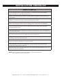
INSTALLATI ON CHECKLI ST
PR I OR TO START-UP
Locate nameplate and record the serial number. It will be necessary when ordering
replacement parts or requesting warranty service.
Follow cut out dimension provided for specic models to properly size the opening for
your drop in.
Condenser coil must be facing a ventilated opening in the cabinet.
Check cord and plug of unit to assure no damage has occurred to these components.
Assure all refrigeration lines are clear of obstruction before, during, and after being
installed into the counter.
Check all sheet metal surrounding the mechanical compartment to assure no damage has
occurred in these areas.
The cold well should have its own dedicated electrical supply line.
Plumbing connections have been made.
Plug in unit and turn ON main on/off power switch.
Allow unit time to cool down to temperature. A layer of frost will form and remain
around the inside perimeter of the rail.
Conrm that the unit is holding temperature. Set control to desired temperature for your
particular ambient and altitude.
NOTE: Failure to follow installation guidelines and recommendations
may void the warranty on your unit.

ÎÈäÎÎÊ,iÛ°Êä®ÊUÊ`Ê`ÊÀ«Ê7iÊ"«iÀ>ÌÊEÊ>ÀiÊ>Õ>ÊUÊ£Î
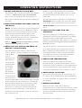
OPE RATI N G INSTRUCT I ONS
1. DO NOT ADD WATER TO COLD WELL
Alto-Shaam cold wells do not require the addition
of water. Adding water is not recommended
since water will accelerate the deterioration of
the product and may damage the unit voiding the
warranty.
2. P L A CE PAN DIVIDERS AND EMPTY PANS IN
THE WELLS
NOTE: No matter what type of pan configuration
chosen, pan separator bars or divider bars must
be used to close all gaps between pans, and all
gaps between the pans and the edges of the
wells. If these gaps are not closed, cold will
escape, distribution will be uneven, and uniform
temperature will be difficult to maintain.
This is a VERY important requirement to follow
whenever this appliance is in use.
3. P RESS THE "ON" SWITCH AND BEGIN TO
PRECHILL THE COLD WELL
The cold temperature control is preset at the
factory. Due to varying conditions (i.e. elevation,
food product,
type of
operation, etc.)
adjustments
can be made
(within limits)
by turning
the control
dial until
the desired
temperature is
reached. Please
allow 24 hours
between adjustments. The control knob is located
on the unit base by the compressor. Turning the
knob clockwise will result in increased cooling.
Keep the arrow on the knob pointed within
the green arc. Turning it clockwise beyond the
green can result in freeze-up, while turning it
counterclockwise beyond the green arc will shut
the compressor off.
NOTE: If your cold pan temperature remains
too warm and your temperature control is at the
maximum setting, please contact your service
technician.
The unit should be pre chilled for a minimum of
30 minutes before loading the unit with chilled
food. If the unit is started at the full off position,
30-45 minutes may be necessary for unit to cool
down.
4. L O A D CHILLED FOODS INTO THE
APPLIANCE
After pre chilling, place cold foods into the pre
chilled pans located in the appliance or exchange
the pans with pre-filled product pans. This
appliance is designed for the purpose of cold food
holding. Product entering the cold pan must be at
40°F (4°C) or less.
All pan divider bars required must be utilized
at all times with the pan configuration chosen.
Before loading food into the unit, use a pocket-
type thermometer to make certain all products
are within the cold safe zone with an internal
temperature of 36° to 40°F (2° to 4°C).
5. C H E C K FOOD TEMPERATURES
After all products are loaded into the unit,
periodically use a pocket thermometer to check
each item to make certain the correct temperatures
are being maintained. Proper temperature range
is between a minimum of 36° to 40°F (2° to 4°C).
6. SERVE FRESH, COLD FOOD
Keep cold foods looking fresh. Occasionally stir
or rotate food as needed. Wipe spills immediately
to ensure maximum eye appeal and to ease end of
day cleanup.
7. EVENING SHUTDOWN
Remove product at the end of the day's
preparation. Turn off the cold well with the switch
located on the base by the compressor. Cleaning
may be performed once the frost has melted off
the rail surface.

ÎÈäÎÎÊ,iÛ°Êä®ÊUÊ`Ê`ÊÀ«Ê7iÊ"«iÀ>ÌÊEÊ>ÀiÊ>Õ>ÊUÊ£{
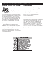
PROTECTING STAINLESS STEEL SURFACES
It is important to guard against corrosion
in the care of stainless steel
surfaces. Harsh, corrosive,
or inappropriate chemicals
can completely destroy the
protective surface layer
of stainless steel. Abrasive
pads, steel wool, or metal implements will abrade
surfaces causing damage to this protective coating
and will eventually result in areas of corrosion.
Even water, particularly hard water that contains
high to moderate concentrations of chloride, will
cause oxidation and pitting that result in rust
and corrosion. In addition, many acidic foods
spilled and left to remain on metal surfaces are
contributing factors that will corrode surfaces.
Proper cleaning agents, materials, and
methods are vital to maintaining the appearance
and life of this appliance. Spilled foods should be
removed and the area wiped as soon as possible
but at the very least, a minimum of once a day.
Always thoroughly rinse surfaces after using a
cleaning agent and wipe standing water as quickly
as possible after rinsing.
CLEANING AGENTS
Use non-abrasive cleaning products designed for
use on stainless steel surfaces. Cleaning agents
must be chloride-free compounds and must not
contain quaternary salts. Never use hydrochloric
acid (muriatic acid) on stainless steel surfaces.
Always use the proper cleaning agent at the
manufacturer's recommended strength.
Contact your local cleaning supplier for
product recommendations.
CLEANING MATERIALS
The cleaning function can usually be accomplished
with the proper cleaning agent and a soft, clean
cloth. When more aggressive methods must be
employed, use a non-abrasive scouring pad on
difficult areas and make certain to scrub with the
visible grain of surface metal to avoid surface
scratches. Never use wire brushes, metal scouring
pads, or scrapers to remove food residue.
CLEANING AND PREVENTATIVE MAINTENANCE
CAUTION
TO PROTECT STAINLESS STEEL
SURFACES, COMPLETELY AVOID
THE USE OF ABRASIVE CLEANING
COMPOUNDS, CHLORIDE BASED
CLEANERS, OR CLEANERS
CONTAINING QUATERNARY SALTS.
NEVER USE HYDROCHLORIC ACID
(MURIATIC ACID) ON STAINLESS
STEEL. NEVER USE WIRE
BRUSHES, METAL SCOURING
PADS OR SCRAPERS.
N
O
W
I
R
E
B
R
U
S
H
E
S
N
O
S
T
E
E
L
P
A
D
S
N
O
S
C
R
A
P
E
R
S

ÎÈäÎÎÊ,iÛ°Êä®ÊUÊ`Ê`ÊÀ«Ê7iÊ"«iÀ>ÌÊEÊ>ÀiÊ>Õ>ÊUÊ£x
C ARE AND CLE ANI N G
INTERIOR:
1. Disconnect appliance from the power source. Let
unit begin to return to ambient temperature.
2. After the frost has melted off the rail of the
appliance, remove all detachable items such
as pans and divider bars. Clean these items
separately.
3. Drain water from the wells daily.
4. Remove any food scraps.
5. Wipe the interior metal surfaces with a paper towel
to remove any remaining food debris.
6. Clean interior with a damp cloth or sponge and
any good commercial detergent at the
recommended strength.
7. For dried-on food deposits, use a non-caustic and
non-toxic commercial oven cleaner appropriate
for the interior surface. Follow the product
manufacturer’s instructions carefully for the use
of this product. Any commercial oven cleaner
must be approved for use on food contact areas.
Remove soil with the use of a plastic scouring
pad.
8. Rinse surfaces by wiping with a clean cloth or
sponge and clean warm water.
9. Remove excess water with a sponge and wipe dry
with a clean cloth or air dry. Leave area open
until interior is completely dry. Replace divider
bars and pans.
10. Interior can be wiped with a sanitizing solution
after cleaning and rinsing. This solution must be
approved for use on stainless steel food contact
surfaces.
DO NOT USE ABRASIVE CLEANING COMPOUNDS.
Always follow appropriate state or local health
(hygiene) regulations regarding all applicable
cleaning and sanitation requirements for food
service equipment.
NOTE: Always allow the frost to melt off the rail
of the appliance before cleaning.
CL E AN THE APPLIANCE DAILY.
NOTE:
Completely avoid
the use of abrasive cleaning
compounds, chloride-based
cleaners, or cleaners containing
quaternary salts. To protect
metal finish on stainless steel,
never use hydrochloric acid
(muriatic acid).
The cleanliness and
appearance of this appliance
will contribute considerably
to operating efficiency and
savory, appetizing food.
Good equipment kept clean
works better and lasts longer.
DANGER
DISCONNECT UNIT FROM
POWER SOURCE BEFORE
CLEANING OR SERVICING.
DANGER
AT NO TIME SHOULD THE INTERIOR
OR EXTERIOR BE STEAM CLEANED,
HOSED DOWN, OR FLOODED WITH
WATER OR LIQUID SOLUTION OF
ANY KIND. DO NOT USE WATER JET
TO CLEAN.
SEVERE DAMAGE OR
ELECTRICAL HAZARD
COULD RESULT.
WARRANTY BECOMES VOID IF
APPLIANCE IS FLOODED

ÎÈäÎÎÊ,iÛ°Êä®ÊUÊ`Ê`ÊÀ«Ê7iÊ"«iÀ>ÌÊEÊ>ÀiÊ>Õ>ÊUÊ£È
Food fl avor and aroma are usually so closely related
that it is diffi cult, if not impossible, to separate them.
There is also an important, inseparable relationship
between cleanliness and food fl avor. Cleanliness, top
operating effi ciency, and appearance of equipment
contribute considerably to savory, appetizing foods. Good
equipment that is kept clean, works be er and lasts longer.
Most food imparts its own particular aroma and many
foods also absorb existing odors. Unfortunately, during
this absorption there is not distinction between GOOD
and BAD odors. The majority of objectionable fl avors
and odors troubling food service operations are caused by
bacteria growth. Sourness, rancidity, mustiness, stale or
other OFF fl avors are usually the result of germ activity.
The easiest way to insure full, natural food fl avor is
through comprehensive cleanliness. This means good
control of both visible soil (dirt) and invisible soil
(germs). A through approach to sanitation will provide
essential cleanliness. It will assure an a ractive
appearance of equipment, along with maximum effi ciency
and utility. More importantly, a good sanitation program
provides one of the key elements in the prevention of
food-borne illnesses.
A controlled holding environment for prepared foods is
just one of the important factors involved in the prevention
of food-borne illnesses. Temperature monitoring and
control during receiving, storage, preparation, and the
service of foods are of equal importance.
The most accurate method of measuring safe temperatures
of both hot and cold foods is by internal product
temperature. A quality thermometer is an eff ective tool for
this purpose, and should be routinely used on all products
that require holding at a specifi c temperature.
A comprehensive sanitation program should focus on
the training of staff in basic sanitation procedures. This
includes personal hygiene, proper handling of raw foods,
cooking to a safe internal product temperature, and
the routine monitoring of internal temperatures from
receiving through service.
Most food-borne illnesses can be prevented through
proper temperature control and a comprehensive
program of sanitation. Both these factors are important
to build quality service as the foundation of customer
satisfaction. Safe food handling practices to prevent food-
borne illness is of critical importance to the health and
safety of your customers.
HACCP, an acronym for Hazard Analysis (at) Critical
Control Points, is a quality control program of operating
procedures to assure food integrity, quality, and safety.
Taking steps necessary to augment food safety practices
is both cost eff ective and relatively simple. While HACCP
guidelines go far beyond the scope of this manual,
additional information is available by contacting:
CENTER FOR FOOD SAFETY AND APPLIED
NUTRITION FOOD AND DRUG ADMINISTRATION
1-888-SAFEFOOD
INTERNAL FOOD PRODUCT TEMPERATURES
HOT FOODS
DANGER ZONE 40° TO 140°F (4° TO 60°C)
CRITICAL ZONE 70° TO 120°F (21° TO 49°C)
SAFE ZONE 140° TO 165°F (60° TO 74°C)
COLD FOODS
DANGER ZONE ABOVE 40°F (ABOVE 4°C)
SAFE ZONE 36° TO 40°F (2° TO 4°C)
FROZEN FOODS
DANGER ZONE ABOVE 32°F (ABOVE 0°C)
CRITICAL ZONE 0° TO 32°F (-18° TO 0°C)
SAFE ZONE 0°F or below (-18°C or below)
S ANI TATI ON

ÎÈäÎÎÊ,iÛ°Êä®ÊUÊ`Ê`ÊÀ«Ê7iÊ"«iÀ>ÌÊEÊ>ÀiÊ>Õ>ÊUÊ£Ç
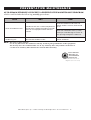
PREVENTATIVE MAI NTE NANCE
ALTO-SHAAM STRONGLY SUGGESTS A PREVENTATIVE MAINTENANCE PROGRAM
which would include the following monthly procedures:
TASK WHY HO W
Clean all condenser coils
Condenser coils are a critical component in
the life of the compressor and must remain
clean to assure proper air flow and heat
transfer.
Clean the condenser coils with coil
cleaner and/or a vacuum, cleaner and
brush.
Brush coil in direction of fins, (usually
vertical) to avoid damage or restrict air
from passing through the condenser.
Clean fan blade on the
condensing unit
>ÊL>`iÊV>ÊViVÌÊ`ÕÃÌÊ>`ÊÌÀ>ÃviÀÊÌ>ÌÊ
dust into the condenser coils.
Clean the fan blade with a vacuum,
cleaner and brush.
NOTE: Do not use sharp utensils.
Use of any filter over the condenser coil may result in poor performance of the equipment.
The factory does not recommend the use of any auxiliary filter. Any failures of the unit as
a result of an auxiliary filter will not be covered under warranty.
5-Year Limited
Warranty on
self-contained
compressor
Effective from date of
shipment. (EXCLUDES LABOR)

ÎÈäÎÎÊ,iÛ°Êä®ÊUÊ`Ê`ÊÀ«Ê7iÊ"«iÀ>ÌÊEÊ>ÀiÊ>Õ>ÊUÊ£n
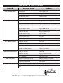
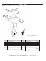
TROUBL E SH OOTI N G
PROBL E M POSSIBLE CA U S E RE M EDY
UNIT WILL NOT COOL
Thermostat off Turn thermostat on
Unit unplugged Plug in appliance
Circuit breaker tripped Replace breaker
Unknown problem Call service agency
UNIT DOESN'T RUN
No power to unit Plug in appliance (check power switch)
Temperature control turned off Check temperature control
Temperature control faulty Test temperature control
Compressor overheated Clean condenser coil
Condenser fan faulty Service condenser fan
Overload protector faulty Test overload
Compressor relay faulty Test relay
Compressor faulty Call service agency
UNIT SHORT CYCLES
Condenser coil dirty Clean coil
Condenser fan faulty Service fan and motor
Compressor faulty Call service agency
Overload repeatedly tripping Check outlet voltage
UNIT RUNS CONSTANTLY
Condenser coil dirty Clean coil
Condenser fan faulty Service condenser motor
Low on refrigerant Call service agency
UNIT TOO COLD
Temperature control set too low Adjust control to raise setting
Temperature control faulty Test control
UNIT NOISY
Compressor mountings loose or hardened
Tighten or replace compressor
mountings
Condenser fan damaged or hitting fan
shroud
Inspect condenser fan
La page est en cours de chargement...
La page est en cours de chargement...
La page est en cours de chargement...
-
 1
1
-
 2
2
-
 3
3
-
 4
4
-
 5
5
-
 6
6
-
 7
7
-
 8
8
-
 9
9
-
 10
10
-
 11
11
-
 12
12
-
 13
13
-
 14
14
-
 15
15
-
 16
16
-
 17
17
-
 18
18
-
 19
19
-
 20
20
-
 21
21
-
 22
22
-
 23
23


Alto-Shaam 200-CW Installation Operation & Maintenance
- Catégorie
- Chauffe-plats
- Taper
- Installation Operation & Maintenance
dans d''autres langues
- English: Alto-Shaam 200-CW
Documents connexes
Autres documents
-
NAPOLEON 1450M Le manuel du propriétaire
-
Bradley Express ELX Series Guide d'installation
-
Danby 3824-527 Le manuel du propriétaire
-
NAPOLEON 1400ML Le manuel du propriétaire
-
Robot Coupe R8 Instructions of use
-
Garland CPO-ED-12H Manuel utilisateur
-
 Quadrafire 5700 Step Top Wood Stove Guide d'installation
-
Zoom R16 Manuel utilisateur
-
Rotel RMB-1085 Le manuel du propriétaire
-
