Pioneer SDA-BS1 Le manuel du propriétaire
- Taper
- Le manuel du propriétaire

SDA-BS1
ADD-ON BLIND SPOT DETECTION SYSTEM
LICENSE PLATE BAR TYPE FOR UNIVERSAL
APPLICATION
Instruction Manual
and Installation Guide
Important (Serial number)
The serial number is located on the top of the main unit. For your own security and
convenience, be sure to record the number.
English

Precaution ................................................................3
Information to Customer.............................................................3
Important Safety Information.....................................................4
After-Sales Service .......................................................................5
One Year Limited Warranty..........................................................5
Visit our Website ..........................................................................5
Alert Conditions.......................................................6
System Indicators.....................................................6
Item List ....................................................................8
Installation Diagram ................................................9
Wire Connection Diagram .....................................10
Installation Guide ..................................................11
Step 1: License Plate Bar Installation .......................................12
Step 2: Left/Right Turn Signal Installation...............................13
Step 3: LED Indicator Installation .............................................13
Step 4: Speaker Installation.......................................................14
Step 5: GPS Antenna Installation ..............................................14
Step 6: Main Unit Installation ...................................................14
Technical Specifications ........................................15
Troubleshooting.....................................................16
Contents
Thank you for buying this Pioneer product.
Please read through these instructions so you will know how to
operate this product properly. After you have finished reading the
instructions, keep this document in a safe place for future reference.
-2-
English

Precaution
Information to Customer
FCC ID: IYASDA-BS100
IC: 25782-SDABS100
- This device contains license-exempt transmitter(s)/receiver(s) that complies with Part 15 of FCC
Rules and Innovation, Science, and Economic Development Canada license-exempt RSS(s).
Operation is subject to the following two conditions: (1) this device may not cause interference, and
(2) this device must accept any interference, including interference that may cause undesired
operation of this device.
-
-
The antenna cannot be removed (or replaced) by user.
This equipment complies with FCC/ISED radiation exposure limits set forth for an uncontrolled
environment and meets the FCC radio frequency (RF) Exposure Guidelines and RSS-102 of the ISED
radio frequency (RF) Exposure rules. This equipment has very low levels of RF energy that are
deemed to comply without Maximum Permissible Exposure evaluation (MPE), but the equipment
should be installed and operated at least 20cm from a person’s body.
Information to User
- Alteration or modifications carried out without appropriate authorization may invalidate the user's
right to operate the equipment.
NOTE: This equipment has been tested and found to comply with the limits for a Class B digital device,
pursuant to Part 15 of the FCC Rules. These limits are designed to provide reasonable protection
against harmful interference in a residential installation. This equipment generates, uses and can
radiate radio frequency energy and, if not installed and used in accordance with the instructions, may
cause harmful interference to radio communications. However, there is no guarantee that
interference will not occur in a particular installation. If this equipment does cause harmful
interference to radio or television reception, which can be determined by turning the equipment off
and on, the user is encouraged to try to correct the interference by one or more of the following
measures:
- Reorient or relocate the receiving antenna.
- Increase the separation between the equipment and receiver.
- Connect the equipment into an outlet on a circuit different from that to which the receiver is
connected.
- Consult the dealer or an experienced radio/TV technician for help.
FEDERAL COMMUNICATIONS COMMISSION SUPPLIER'S DECLARATION OF CONFORMITY
Product Name: ADD-ON BLIND SPOT DETECTION SYSTEM LICENSE PLATE BAR TYPE FOR
UNIVERSAL APPLICATION
Model Number: SDA-BS1
Responsible Party Name: PIONEER ELECTRONICS (USA) INC.
SERVICE SUPPORT DIVISION
Address: 2050 W. 190TH STREET, SUITE 100, TORRANCE, CA 90504, U.S.A.
Phone: 1-800-421-1404
URL: http://www.pioneerelectronics.com
-3-
CAN ICES-3 B/NMB-3 B
English

Important Safety Information
The license plate bar’s performance can be affected if installed on a vehicle that has items
obstructing the license plate location (e.g. bike rack, trailer). In addition, the license plate bar
cannot be installed correctly if the license plate is offset or on the far side of the vehicle and not
centered.
This system can be used on any vehicle that has a standard license plate location but can be affected
by metal objects that may block or interfere with the operation of the system.
The following may compromise the effectiveness of the system:
Vehicles with permanent trailers attached.
Vehicles with metal obstructions in front of the license plate, i.e. spare tire mount, rear bike racks
or equipment for disabled persons.
Standard license plates that are mounted on the right or left side of the vehicle.
(Center Installation Required)
Situations that cannot be detected
If a vehicle is passing your vehicle.
Your vehicle is moving slower than the sensing speed threshold setting, such as in slow moving
traffic.
When your vehicle is reversing, the relative speed between your vehicle and objects is less than
5 mph (8 km/h).
If a vehicle is approaching / overtaking your vehicle and the relative speed between your vehicle
and the overtaking vehicle is greater than 50 mph (80 km/h). For example, if you are traveling at
55 mph (88 km/h), the system cannot detect vehicles approaching from behind if their speed
exceeds 105 mph (169 km/h).
Situations that may affect system detection accuracy
Metal objects are in the direct path of the sensing signal.
Weather such as heavy rain and snow, and icy road conditions, which can cause changes in
sensitivity.
Gravel roads, which may cause interference due to dust and flying stones.
・
・
・
・
・
・
・
・
・
・
・
・
THIS PRODUCT FUNCTIONS AS AN AID
FOR NOTIFYING THE PRESENCE OF OBSTACLES IN VEHICLE BLIND SPOTS.
IT DOES NOT DETECT ALL DANGERS AND OBSTACLES
AND IS NOT A SUBSTITUTE FOR YOUR JUDGEMENT AND CAREFUL ATTENTION.
BEFORE ANY MANEUVER, VISUALLY CHECK BOTH SIDES OF THE VEHICLE TO CONFIRM.
WARNING
WARNING
Check license plate bar unit installation before driving.
- Are the screws loose?
- Is the unit firmly secured?
- If the unit comes loose while you are driving, it may cause an accident.
・
-4-
CAUTION
・Special vehicle conditions that should be considered
During system startup and initialization, it may take up to 2 minutes for the system to establish a GPS
connection. If the vehicle is driven before a GPS connection is established or if the GPS connection is
interrupted (inside a tunnel, parking structure, etc.), the system may not function properly, producing
incorrect or false warnings or failing to produce a warning. Once the GPS connection is established
or re-established, both LED indicators will flash twice to indicate the system is ready for use.
English

After-Sales Service
Please contact the authorized Pioneer dealer from which you purchased this product for after-sales
service (including warranty service) or any other information. If you still need help, please contact
our Customer Support Division.
Please do not ship your product in for repair without first contacting Customer Support for return
authorization. Please review the Limited Warranty for instructions on receiving warranty service.
-USA & CANADA
Pioneer Electronics (USA) Inc.
CUSTOMER SUPPORT DIVISION
P.O. Box 1720 Long Beach, CA 90801-1720
Visit our Website
Visit us at the following sites:
In the U.S.: http://www.pioneerelectronics.com
In Canada: http://www.pioneerelectronics.ca
Register your product.
Receive updates on the latest products and technologies.
Download owner’s manuals, order product catalogs, research new products, and much more.
1
2
3
One Year Limited Warranty
When purchased from an authorized Pioneer dealer, this product is covered by Pioneer’s One Year
Limited Warranty. Please visit http://pioneerelectronics.com/warranty to review and download
the full terms and conditions of the Limited Warranty, or you can receive a copy by calling
1-800-421-1404 or writing to the address below.
Customer Support:
Pioneer Electronics (USA) Inc.
P.O. Box 1720, Long Beach, California 90801 U.S.A.
-5-
・
・Do not allow the main unit to come into contact with liquids. Electrical shock, damage to the product,
smoke, and overheating could result from contact with liquids. (The license plate bar is waterproof
with IPX6/IPX7 rating)
・Do not disassemble or modify this product, as there are high-voltage components inside that may
cause an electric shock. Be sure to consult your dealer or the nearest authorized Pioneer service
company for internal inspection, adjustments or repairs.
・Always observe safe driving rules and follow all existing traffic regulations. If you experience difficulty
in operating this product, pull over, park your vehicle in a safe location and apply the parking brake
before making the necessary adjustments.
・Keep this manual handy as a reference for operating procedures and safety information.
Pioneer does not recommend that you install this product yourself. This product is designed for
professional installation only. We recommend that only authorized Pioneer service company
personnel who have specialized training and experience in mobile electronics set up and
install this product. NEVER SERVICE THIS PRODUCT YOURSELF. Installing or servicing this product
and its connecting cables may expose you to the risk of electric shock or other hazards, and can
cause damage to this product that is not covered by warranty.
English

When the system is on and functioning, the system is designed to detect the following events:
1. Blind spots while driving: Objects in the blind spot areas around your vehicle - in the lanes on the
left/right and directly behind the vehicle at a distance of up to 50 ft (approximately 15.2 m).
2. Blind spots while being passed / overtaken: When vehicles are approaching / overtaking your vehicle
from behind.
3. Cross-Traffic Detection: When your vehicle is reversing, vehicles approaching from your left and
right.
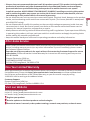
Alert Conditions
CAUTION
The SDA-BS1 only detects objects approaching your vehicle from behind. It does not detect objects
your vehicle is approaching or overtaking. Under certain driving scenarios, the SDA-BS1 may detect
objects in an unintended way. The following conditions below are examples of scenarios where fault
notifications may occur.
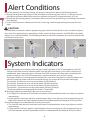
System Indicators
A. When the system is turned on each time (your vehicle ignition or ACC is switched on), both LED
indicators will flash once to indicate system start up and initialization. Once a GPS connection is
established, which may take up to 2 minutes, both LED indicators will flash twice to indicate the
system is ready for use. The GPS connection is used to calculate your vehicle's speed.
The system features a sensing speed threshold that is set when the system is installed. When your
vehicle is traveling slower than this threshold setting, the system will not produce warnings.
Threshold 1: System warns at any speed above 5 mph (8 km/h)
Threshold 2: System warns at any speed above 10 mph (16 km/h)
Threshold 3: System warns at any speed above 15 mph (24 km/h)
Threshold 4*: System warns at any speed above 20 mph (32 km/h)
*The factory default sensing speed threshold is Threshold 4.
B.
1. The Right LED indicator will illuminate and remain illuminated when there is an object or vehicle
approaching.
2. If your vehicle's right turn signal is activated when there is an object or vehicle approaching, the
Right LED indicator will flash repeatedly and the included speaker will beep (bi-bi-bi) one time.
C.
1. The Left LED indicator will illuminate and remain illuminated when there is an object or vehicle
approaching.
2. If your vehicle's left turn signal is activated when there is an object or vehicle approaching, the
Left LED indicator will flash repeatedly and the included speaker will beep (bi-bi-bi) one time.
Blind spot detection toward the right rear of your vehicle:
Blind spot detection toward the left rear of your vehicle:
-6-
Fig 1 Fig 2 Fig 3 Fig 4
English

D. Cross-Traffic Detection:
1. When your vehicle is reversing and the system detects an object or vehicle approaching from
your right, the Right LED indicator will illuminate and remain illuminated and the included speaker
will beep .
2. When your vehicle is reversing and the system detects an object or vehicle approaching from
your left, the Left LED indicator will illuminate and remain illuminated and the included speaker
will beep .
Note: The system will not detect or warn of standing objects or objects moving under
5 mph (8 km/h).
repeatedly
repeatedly
-7-
English

License Plate Bar with
Configurable Radar Sensors
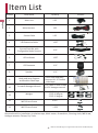
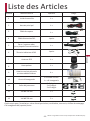
Number Item Name Quantity Pictures
1 Main Unit 1 PC
21 PC
3
1 PC
4
LED Indicator 1 SET
6
GPS Antenna 1 PC
7
Speaker 1 PC
8
Hook-and-loop Fastener
and Double-sided Tape
4 PCS
& 1 PC
tape
hook-and-loop
fastener Double
-sided
9
2 PCS M6*12 mm Screws
& 1 PC Hexagon wrench
Screws & Hexagon Wrench
5
10
Wedges
11
2 PCS 5 degree
2 PCS 10 degree
2 PCS 15 degree
M6*16 mm Screw 2 PCS
12
M6*20 mm Screw 2 PCS
Item List
Required tools for installation: Insulation tape; Multi-meter; Screwdriver; Cleaning cloth; M6 Screw;
Hexagon wrench; Clamps; Pry Tools.
-8-
Main Harness
LED Extension Cable
Sensor Cable
1 SET
1 PC
13
*3M and the 3M logo are registered trademarks of 3M Company.
English

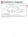
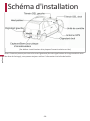
(Default: installed on the bottom of rear license plate)
Installation Diagram
-9-
Note: If you cannot connect to the rear tail lamp (turn signal lights combined with brake lights),
then connect at the front fuse box.
English

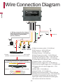
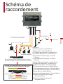
Wire Connection Diagram
① Main connectors cable - 2.6 ft (80 cm)
② GPS antenna - 10.5 ft (320 cm)
③ Red L sensor - 2.6 ft (80 cm)
④ Yellow R sensor - 2.6 ft (80 cm)
⑤ Red LED extension cable - 22.9 ft (700 cm)
⑥ Yellow LED extension cable - 22.9 ft (700 cm)
⑦ Red Left LED indicator cable - 1.6 ft (50 cm)
⑧ Yellow Right LED indicator cable - 1.6 ft (50 cm)
⑨ Speaker cable - 10.5 ft (320 cm)
⑩ Green reverse trigger wire - 5.9 ft (180 cm)
⑪ Pink left-turn signal trigger wire - 5.9 ft (180 cm)
⑫ Orange right-turn signal trigger wire - 5.9 ft
(180 cm)
⑬ Black GND - 5.9 ft (180 cm)
⑭ Red ACC/IGN - 15.7 ft (480 cm)
⑮ Red sensor extension cable - 22.9 ft (700 cm)
⑯ Yellow sensor extension cable - 22.9 ft (700 cm)
If cannot be connected to rear tail lamp (turn
signal lights maybe combined with brake lights)
then connect at the front fuse box.
Speaker
License Plate Bar with two sensors built inside
(Default: installed on the bottom of license plate)
1. Wiring connection for License
Plate Bar installed at the bottom
of the vehicle's license plate.
(Factory default)
2. Wiring connection for License Plate Bar
installed at the top of the vehicle's license plate.
(Option 2: installed on the top of license plate)
R sensor
L sensor
FUSE (2 A)
GPS Antenna
Left LED
indicator
Right LED
indicator
①
②
③
④
⑤⑥
⑦⑧
⑨
⑩
⑪
⑫
⑬
⑭
⑮
⑯
-10-
English

Installation Guide
Do not install the Main Unit or the LED Indicators where it may (i) obstruct the driver's vision,
(ii) impair the performance of any of the vehicle's operating systems or safety features, including
air bags or hazard lamp buttons or (iii) impair the driver's ability to safety operate the vehicle.
Never install this product in front of or next to the place in the dashboard, door, or pillar from
which one of your vehicle's airbags would deploy. Please refer to the vehicle's owner's manual for
reference to the deployment area of the airbags.
Do not install the Main Unit in places subject to high temperatures or humidity, such as:
- Close to a heater, vent or air conditioner.
- Places that may be exposed to rain, such as close to the door or on the vehicle's floor.
If the Main Unit is installed in the passenger compartment, anchor it securely so it does not break
free while the vehicle is moving and cause injury or an accident.
Secure all wiring with cable clamps or electrical tape. Do not allow any bare wiring to remain
exposed.
Make sure that the cables and wires will not interfere with or become caught in any of the
vehicle's moving parts, especially brake, doors, or any of the vehicle's controls.
If the wiring of this unit is located under a front seat, make sure it does not obstruct seat movement.
Route all leads and cords carefully around the sliding mechanism so they do not get caught or
pinched in the mechanism and cause a short circuit.
Do not shorten any leads. If you do, the protection circuit (fuse holder, fuse resistor or filter, etc.)
may fail to work properly.
When replacing the fuse, be sure to use a fuse only of the rating prescribed on this product.
Use only the parts included with the unit to ensure proper installation. The use of unauthorized
parts can cause malfunctions.
Never feed power to other electronic products by cutting the insulation of the power supply lead of
this product and tapping into the lead. The current capacity of the lead will be exceeded, causing
overheating.
Use this unit with a 12-volt battery and negative grounding only. Failure to do so may result in a fire
or malfunction.
Disconnect the negative terminal of the battery before installation.
Secure the wiring with cable clamps or adhesive tape. Wrap adhesive tape around wiring that comes
into contact with metal parts to protect the wiring.
Do not perform installation in rain or fog.
Do not cover the license plate number, name of issuing state and/or registration decals. It is illegal in
some states if these items are covered by the license plate bar.
・For professional installation only by personnel with specialized training and experience in mobile
electronics.
・
・
・
・
・
・
・
・
・
・
・
・
・The graphical symbol placed on the product means direct current.
・
・
・
・
WARNING
-11-
English

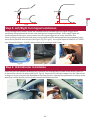
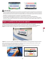
Step 1: License Plate Bar Installation
Two installation options available: the License Plate Bar can be installed on the bottom or on top of
the rear license plate. The default is installation on the bottom of the license plate. Route the cable
behind the license plate into the vehicle and connect to the system Main Unit.
Option 1. Install the License Plate Bar on the bottom of the license plate (see Fig 5).
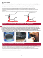
Option 2. The License Plate Bar can also be installed at the top of the license plate if the bottom is
obstructed or does not have sufficient space for License Plate Bar installation (see Fig 6).
Note: When using Option 2, please exchange the left and right connectors of the sensor for LED
in order to get the correct signal (see Fig 7).
On certain vehicles where the license/tag plate position is higher than 4 ft (1.2 m) and not
perpendicular to the ground, please use the included wedges along with different size screws to ensure
that the bar is properly aligned perpendicular to the ground, but also secured at rear license/tag plate.
Please select the appropriate wedges behind the license plate bar to find an accurate angle as close
to perpendicular to ground as possible. Use the license plate screws to attach the appropriate wedge
for correct installation (see Fig 8 and Fig 9). This product cannot be used for front vehicle application.
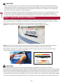
CAUTION
Ensure that the connector is inserted correctly and according to the corresponding label and the
arrow marks of the wire connector at the connection point. When connecting, ensure that the KEY
or raised area of the connector mates with the opposite connector. Do not force any connection
and ensure that the connector mates properly.
To avoid any damage to the connectors, align the arrows on each of the corresponding items, then
firmly press connectors together to ensure a good connection. Failure to properly install and
connect the system components may cause damage to the product and operation of the system.
・
・
Fig 6
CAUTION
-12-
Fig 7
Fig 5
Option 2
R sensor
L sensor
English

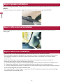
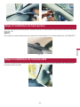
Using a voltage multi-meter, locate the isolated left and isolated right turn signal trigger wires,
commonly found behind the vehicle's left and right tail lamp assemblies.
Once verified, connect the left and right turning signal wires to the appropriate corresponding input
wires of the SDA-BS1 wire harness (see Fig 10, Fig 11, Fig 12). Turn signal inputs of SDA-BS1 is +12VDC
only (not switchable to -12VCD); please check with a voltage multi-meter.
If turn signal lights are
combined with brake lights, then connect the turn signal trigger wires at the front fuse box.
Fig 10 Fig 11 Fig 12
Step 2: Left/Right Turn Signal Installation
Step 3: LED Indicator Installation
Install the Left LED indicator and Right LED indicator in a location that is visible to the driver, ideally in
or around the vehicle's A-pillars (see Fig 13, Fig 14). Place the LED indicators away from the side curtain
air bags, so as not to hinder the deployment of airbag function. Appropriate placement is usually at the
lowest part of the A-pillars, but you must consult the vehicle manual.
Fig 13 Fig 14
Fig 9
Fig 8
Wedge Wedge
-13-
English

When installing the GPS Antenna, make sure it is not obstructed by any panels inside the vehicle
(see Fig 16).
Fig 16
Step 4: Speaker Installation
While installing the speaker, make sure it is not obstructed by any panels inside the vehicle
(see Fig 15).
NOTE:
To adjust volume on the speaker, toggle the switch to the desired setting, “HI/LOW/OFF”.
Fig 15
Step 5: GPS Antenna Installation
Step 6: Main Unit Installation
The Main Unit is not waterproof and must be installed securely inside the vehicle.
Find a suitable location for the Main Unit, Confirm that
the sensor wire length is sufficient to reach from the bumper to the Main Unit location before
proceeding.
Soldering all wiring is recommended. Securely tape and insulate all connections soldered.
・
・similar to an alarm or remote start system.
・
・Secure all wires neatly to hide and prevent wire pinch.
1. +12 VDC ACC/IGN - Locate the +12 VDC (ACC/IGN) and connect the red wire from the Main Unit.
2. Chassis Ground (Black) - Connect the black wire from the Main Unit to chassis ground.
3. +12 VDC reverse signal (Green) - Locate the +12 VDC reverse signal (reverse light or other location)
and connect the green wire from the Main Unit.
4. Orange Right-Turn signal Trigger - Locate the +12 VDC Isolated turn signal and connect the Right
(Orange) wire from the Main Unit.
-14-
English

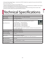
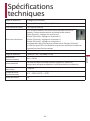
52 degrees ( ) HorizontalDetection Range
Speed Range 0.5 mph (0.8 km/h) 137 mph (220 km/h)~
Speed Accuracy < 0.5 mph (0.8 km/h)
Speed Restriction
1. The GPS needs to detect restricted speed to activate
the sensors. There are four speed restriction options:
5 mph (8 km/h) --- Switch Setting 1
10 mph (16 km/h) -- Switch Setting 2
15 mph (24 km/h) -- Switch Setting 3
20 mph (32 km/h) -- Switch Setting 4
Default speed setting is 20 mph (32 km/h).
2. If no GPS signal is detected or satellites not found, the system will be
activated at any speed.
Direction of Movement Approached by vehicles
Detection Range 1 ft (0.3 m) 50 ft (15 m)~
Operating Voltage 9 18 V~
Waterproof
Working Current
Working Temperature
< 100 mA
-4°F ~ 158°F (-20℃ 70℃)~
Technical Specifications
License Plate Bar: IPX6/IPX7
Other items such as cables and Main Unit: NOT waterproof
5. Pink Left-Turn Signal Trigger - Locate the +12 VDC Isolated turn signal and connect the Left (Pink)
wire from the Main Unit.
6. Connect the power harness into the Main Unit.
7. Make all the appropriate connections (LED’s, Speaker, License Plate Bar) on the Main Unit harness.
8.
9. Test the system’s operation, ensuring that all features operate according to this manual. After
operation is tested, finalize connections and secure wires.
Connect the negative terminal of the battery to the vehicle.
FUSE rating value 2 A
-15-
English

-16-
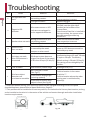
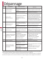
NO. Issues Reasons Solutions
1
Incorrect connection or pins
not making contact
LED light is broken Replace LED light
2
Make sure RED is on the left side and
YELLOW is on the right side if
installed at the bottom of the
License Plate.
If the is installed in
the top position, the sensor wires
must be reconfigured during
installation.
License Plate Bar
3
4
5
Troubleshooting
LED light does not
work
Check the
sure connection is correct
harness and make
Opposite LED
indicator
Microwave sensor or LED
indicators are plugged in
to the opposite connector
Speaker does not work
Wrong connection or pins
not making contact
Check the harness and make
sure connection is correct
Defective Speaker Replace Speaker
Sensor or GPS
does not work
Sensor or GPS Antenna module
is covered by the metal
bumper or other metal
Find the best location where the
sensor or GPS Antenna cannot be
blocked by any metal
Unit does not work
after GPS Antenna is
connected
Blind spot system does not
trigger the sensor if the speed
is less than 20 mph (32 km/h)*
The system features sensing speed
threshold settings of 5 mph, 10 mph,
15 mph or 20 mph. The factory
default setting is 20 mph (32 km/h).
The setting can be changed by the
installer.
6
7
FUSE is blown Over current / Power surge Exchange FUSE (2 A)
Blind area object
detection not
consistent or unstable
Not Installed in center
(See Fig 17) Find the location in the center
of vehicle.
Find the location where the radar
sensing area is not blocked by
objects(s).
**
Installed with wrong angle
(pointing upward)
Installed at a location with
object in front (See Fig18)
* U
** This product can be installed on almost any vehicle, not limited to the license plate location, as long
as the installation location is in the center of the vehicle and meets the angle and other installation
location requirements.
nder the default setting, GPS restriction speed can be changed according to the four speed
threshold options; please refer to Speed Restriction, Page 15.
Fig 17 Fig 18
English

Français
Manuel d'instructions
et guide d'installation
Important (numéro de série)
Le numéro de série se trouve en haut de l'unité principale. Pour votre propre sécurité et
commodité, assurez-vous d'enregistrer le numéro.
SDA-BS1
SYSTÈME DE DÉTECTION D'ANGLES MORTS
AVEC INSTALLATION UNIVERSELLE POUR
PLAQUE D’IMMATRICULATION (BARRE)

Précaution..............................................................19
Informations aux clients............................................................19
Informations importantes sur la sécurité................................20
Service après-vente ...................................................................21
Garantie limitée d'un an ............................................................21
Visitez notre site Web ................................................................22
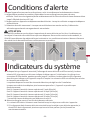
Conditions d'alerte................................................23
Indicateurs du système..........................................23
Liste des Articles ....................................................25
Schéma d'installation ............................................26
Schéma de raccordement ......................................27
Guide d'installation ...............................................28
Étape 1: Installation de la barre de capteurs ..........................29
Étape 2: Connexion des informations de clignotants ............30
Étape 3: Installation des témoins DEL......................................30
Étape 4: Installation du haut-parleur ......................................31
Étape 5: Installation de l'antenne GPS ....................................31
Étape 6: Installation de l'unité de contrôle.............................32
Spécifications techniques .....................................33
Dépannage .............................................................34
Table des matières
Merci d'avoir acheté ce produit Pioneer.
Veuillez bien lire ces instructions afin de faire fonctionner votre
appareil correctement. Suite à la lecture de ces instructions,
conservez ce document dans un endroit sûr pour références
ultérieures.
-18-
Français

Précaution
Informations aux clients
L’émetteur/récepteur exempt de licence contenu dans le présent appareil est conforme à la section
15 des normes FCC et CNR d'innovation, sciences et développement économique Canada applicables
aux appareils radio exempts de licence. L’utilisation est autorisée sous les deux conditions suivantes:
(1) l'appareil ne doit pas produire de brouillage, et (2) l'utilisateur de l'appareil doit accepter tout
brouillage radioélectrique subi, même si le brouillage est susceptible d'en compromettre le
fonctionnement.
- L'antenne ne peut pas être enlevée (ou remplacée) par l'utilisateur.
- Cet appareil est conforme aux limites d’exposition aux rayonnements énoncées pour un
environnement non contrôlé et respecte les règles directrices en radioélectriques (RF) de la FCC
concernant l'exposition aux fréquences radioélectriques (RF) CNR-102 de l’ISDE. Cet appareil émet
une onde-radio (RF) très faible qui est considérée conforme et sans évaluation requise de l’exposition
maximale. Cependant, cet appareil doit être installé et utilisé en gardant une distance de 20 cm ou
plus entre le dispositif rayonnant et le corps humain.
FCC ID: IYASDA-BS100
IC: 25782-SDABS100
-19-
CAN ICES-3 B/NMB-3 B
Informations à l'utilisateur
- Les modifications ou modifications effectuées sans autorisation appropriée peuvent invalider tout
droit d'utiliser cet appareil.
NOTE: Cet appareil a été testé et s'est avéré conforme aux limites d'un appareil numérique de classe B,
conformément à la section 15 de la règlementation FCC. Ces limites sont conçues pour offrir une
protection raisonnable contre les interférences nocives à l’intérieur d’une installation résidentielle.
Cet appareil génère, utilise et peut émettre de l'énergie par radiofréquence. Si ce dernier n'est pas
installé et utilisé conformément aux instructions, il pourra causer des interférences nocives aux
communications radio. Toutefois, rien ne garantit l’exemption d’interférences dans une installation
particulière. Si cet appareil cause de tel interférences à la réception radio ou télé, confirmé par la
désactivation de l’appareil, l'utilisateur est encouragé à essayer de corriger la situation via une ou
plusieurs de ces actions:
l'utilisateur est encouragé à essayer de corriger l’interférence par une ou plusieurs de ces mesures;
- Réorienter ou déplacer l'antenne réceptrice.
- Augmenter la distance entre l’appareil et le récepteur.
- Alimenter l’appareil via une source ou circuit différent de celui auquel l’appareil interfère.
- Consulter le marchand ou un technicien expérimenté en radio/télévision pour obtenir de l'aide.
DECLARATION DE CONFORMITE DE LA FCC « FEDERAL COMMUNICATIONS COMMISSION »
Nom du produit:
Numéro de modèle: SDA-BS1
Nom du parti responsable: PIONEER ELECTRONICS (USA) INC.
DIVISION AU SUPPORT ET SERVICES
Adresse: 2050 W. 190TH STREET, SUITE 100, TORRANCE, CA 90504, U.S.A.
Téléphone: 1-800-421-1404
URL: http://www.pioneerelectronics.com
SYSTÈME DE DÉTECTION D'ANGLES MORTS AVEC INSTALLATIION
UNIVESELLE POUR PLAQUE D’IMMATRICULATION (BARRE)
Français

・Conditions particulières des véhicules à considérer
Pendant le démarrage et l'initialisation de l’appareil, ce dernier peut prendre jusqu'à 2 minutes pour
établir une connexion GPS. Si le véhicule est conduit avant qu'une connexion GPS ne soit établie ou si
la connexion GPS est interrompue (à l'intérieur d'un tunnel, d'une structure de stationnement, etc.),
le système peut ne pas fonctionner correctement, produisant des avertissements incorrects ou faux
ou ne pas générer d'avertissement. Une fois que la connexion GPS est établie ou rétablie, les deux
témoins DEL clignotent deux fois pour indiquer que l’appareil est prêt à être utilisé.
Les performances du capteur (barre) installé sur la plaque d'immatriculation peuvent être affectées
si elle est installée sur un véhicule dont les éléments obstruent l'emplacement de la plaque.
(ex: support à vélos, remorque). Entre-autre, le capteur ne peut être installée correctement si la
plaque d'immatriculation est décalée d’un côté du véhicule et non centrée.
Cet appareil peut être utilisé sur n'importe quel véhicule ayant un emplacement standard de plaque
d'immatriculation mais peut être affecté par des objets métalliques pouvant bloquer ou interférer
avec le fonctionnement du système. Les éléments suivants peuvent compromettre l'efficacité du
système:
・Véhicule avec remorque attachée en permanence.
・Véhicule avec des obstructions métalliques devant la plaque d'immatriculation, ex: pneu de
secours, supports de vélo ou équipement pour personne handicapée.
・Plaque d'immatriculation standard mais située sur le côté droit ou gauche du véhicule.
(Installation centrale requise)
・Situation indétectable
・Si un véhicule dépasse votre véhicule.
・Votre véhicule se déplace plus lentement que le seuil de vitesse de détection préréglé, tel que
circuler dans une congestion.
・Lorsque votre véhicule est en marche arrière et que la vitesse entre votre véhicule et les objets
environnants est inférieure à 5 mph (8 km/h).
・Si un véhicule approche ou dépasse votre véhicule et que la vitesse entre votre véhicule et ce
véhicule est supérieure à 50 mph (80 km/h). Par exemple, si vous roulez à une vitesse de 55mph
(88 km/h), l’appareil ne peut détecter les véhicules s'approchant par l’arrière si leur vitesse est
supérieure à 105 mph (169 km/h).
・Situations pouvant affecter la précision de détection de l’appareil
・Des objets métalliques sont dans la trajectoire immédiate du signal de détection.
・La météo tel qu’une forte pluie ou neige, des conditions routières avec verglas pouvant entraîner
des variations de sensibilité.
・Routes de gravier, pouvant causer des interférences dues à la poussière et projection de pierres.
ATTENTION
Informations importantes sur la sécurité
CET APPAREIL D’AIDE À LA CONDUITE A POUR FONCTION DE NOTIFIER LA
PRÉSENCE D'OBSTACLES DANS LES ANGLES MORTS DU VÉHICULE.
Il NE PEUT DÉTECTER TOUS LES DANGERS ET OBJETS ET N’EST PAS
UN SUBSTITUT POUR VOTRE JUGEMENT ET ATTENTION.
AVANT TOUTE MANOEUVRE, VÉRIFIEZ VISUELLEMENT LES DEUX
CÔTÉS DU VÉHICULE POUR PLUS DE SÉCURITÉ.
AVERTISSEMENT
-20-
Français
La page est en cours de chargement...
La page est en cours de chargement...
La page est en cours de chargement...
La page est en cours de chargement...
La page est en cours de chargement...
La page est en cours de chargement...
La page est en cours de chargement...
La page est en cours de chargement...
La page est en cours de chargement...
La page est en cours de chargement...
La page est en cours de chargement...
La page est en cours de chargement...
La page est en cours de chargement...
La page est en cours de chargement...
La page est en cours de chargement...
La page est en cours de chargement...
-
 1
1
-
 2
2
-
 3
3
-
 4
4
-
 5
5
-
 6
6
-
 7
7
-
 8
8
-
 9
9
-
 10
10
-
 11
11
-
 12
12
-
 13
13
-
 14
14
-
 15
15
-
 16
16
-
 17
17
-
 18
18
-
 19
19
-
 20
20
-
 21
21
-
 22
22
-
 23
23
-
 24
24
-
 25
25
-
 26
26
-
 27
27
-
 28
28
-
 29
29
-
 30
30
-
 31
31
-
 32
32
-
 33
33
-
 34
34
-
 35
35
-
 36
36


Pioneer SDA-BS1 Le manuel du propriétaire
- Taper
- Le manuel du propriétaire
dans d''autres langues
- English: Pioneer SDA-BS1 Owner's manual
Documents connexes
Autres documents
-
Mazda mx-5 2016 Manuel utilisateur
-
MOTO GUZZI California Manuel utilisateur
-
Clarion NX700 Manuel utilisateur
-
Magellan MiVue 320 Manuel utilisateur
-
Voyager VBSD32 Manuel utilisateur
-
Wacker Neuson G625 Manuel utilisateur
-
APRILIA DORSODURO 750 ABS Manuel utilisateur
-
 Furukawa 24GMMR20 Manuel utilisateur
-
Nova 7GB-A 77GHz Millimeter-Wave Radar Manuel utilisateur
