
Page 5 Page 6
Page 1
Copyright© 2015 Enlighted Inc. All rights reserved.
All other brand or product names are trademarks of
their respective companies or organizations.
Technical Support
For questions regarding the installation or operation of
this product, contact Enlighted
Technical Support: support@enlightedinc.com
Company Contact Information
Location: 930 Benecia Ave, Sunnyvale, CA 94085
Phone: +1.650.964.1094
Web: enlightedinc.com
FCC and Canada Compliance Information
This device complies with Part 15 of the FCC Rules and with Industry
Canada license-exempt RSS standards. Operation is subject to the
following two conditions: (1) this device may not cause harmful
interference, and (2) this device must accept any interference received,
including interference that may cause undesired operation. Changes or
modifications not expressly approved by Enlighted Inc. could void the user's
authority to operate the equipment. This equipment generates, uses, and
can radiate radio frequency energy and, if not installed and used in
accordance with the instruction manual, may cause harmful interference
to radio communications. Operation of this equipment in a residential area
is likely to cause harmful interference in which case the user will be required
to correct the interference at his own expense.
Le présent appareil est conforme aux CNR d'Industrie Canada applicables
aux appareils radio exempts de licence. L'exploitationest autorisée aux
deux conditions suivantes: (1) l'appareil ne doit pas produire de brouillage,
et (2) l'utilisateur de l'appareil doit accepter tout brouillageradioélectrique
subi, même si le brouillage est susceptible d'en compromettre le
fonctionnement.
Under Industry Canada regulations, this radio transmitter may only operate
using an antenna of a type and maximum (or lesser) gain approved for the
transmitter by Industry Canada. To reduce potential radio interference to
other users, the antenna type and its gain should be so chosen that the
equivalent isotropically radiated power (e.i.r.p.) is not more than that
necessary for successful communication.
Conformément à la réglementation d'Industrie Canada, le présent émetteur radio
peut fonctionner avec une antenne d'un type et d'un gain maximal (ou inférieur)
approuvé pour l'émetteur par Industrie Canada. Dans le but de réduire les risques de
brouillage radioélectrique à l'intention des autres utilisateurs, il faut choisir le type
d'antenne et son gain de sorte que la puissance isotrope rayonnée équivalente
(p.i.r.e.) ne dépasse pas l'intensité nécessaire à l'établissement d'une communication
satisfaisante.
This radio transmitter IC: 10138A-GW2 has been approved by Industry
Canada to operate with the antenna types listed below with the maximum
permissible gain and required antenna impedance for each antenna type
indicated. Antenna types not included in this list, having a gain greater
than the maximum gain indicated for that type, are strictly prohibited for
use with this device.
Le présent émetteur radio IC: 10138A-GW2 a été approuvé par Industrie Canada pour
fonctionner avec les types d'antenne énumérés ci-dessous et ayant un gain admissible
maximal et l'impédance requise pour chaque type d'antenne. Les types d'antenne
non inclus dans cette liste, ou dont le gain est supérieur au gain maximal indiqué, sont
strictement interdits pour l'exploitation de l'émetteur.
CE
This device complies with the essential requirements and other relevant
requirements of the R&TTE Directive (1999/5/EC). The product is compliant
with the following standards and/or other normative documents - EN 62479,
ETSI EN 301 489-1-17, EN 300 328 and EN 60950-1
•The equipment is Class 1 radio equipment which can be placed on the
market and be put into service without restrictions in accordance with
article 1(3) of Commission Decision 2000/299/EC (Version July 2014).
Gateway (GW)
Model GW-2-01
Installation Instructions
Figure 1: Gateway Unit (front and back)
Shipped Components
• Enlighted Gateway
• Two #6 - 1” screws with standoffs
• Antenna: Nearson S151AH-07826 2.4GHz Swivel
Antenna with 5dBi, 50 Ohm
Tools You May Need
• #2 Philips screwdriver
Supplies You May Need
• Cat-5e or Cat-6 data cable with RJ45 (conforming to
TIA/EIA 568-B) connectors between the gateway
(GW) and PoE Ethernet switch
Model: GW-2-01
FCC ID: AQQ-GW2
IC: 10138A-GW2
93-01246-01-01 Rev04 081215

Page 2
Page 3
Page 4
Caution
• Disconnect all power before installationor service.
• Installationand maintenance must be performed by a qualified
electricianinaccordance with local, state, and nationalelectrical
codes (NEC) and requirements.
Problem Solution
No LED on the
Gateway (GW) is
on or blinking.
• Verify the Cat-6 cable
between the PoE port on
the Ethernet switch and
the Enlighted Gateway
has not been damaged.
• Check that the RJ45
connectors on each end
of the Cat-6 cable are
completely inserted.
• Verify that the PoE
Ethernet switch is powered
and functioning properly.
Red LED on the GW
is on continuously.
Replace the Gateway.
Red LED on the
GW is blinking at
a slow rate and
the green LED is
off.
This is the expected blink
pattern before the
Energy Manager is
connected to the PoE
Ethernet Switch and
made operational.
Red LED on the GW
is off and the green
LED is blinking
rapidly.
This is the expected blink
pattern after the Energy
Manager is connected to
the PoE Ethernet Switch
and made operational,
and before the GW is
commissioned.
Troubleshooting
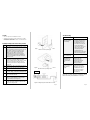
Figure 2: Attach the unit to the wall on screws
with the antenna pointing up
Figure 4: Wiring Diagram for PoE switch and GW
Step Description
1
Determine a location for the GW. The Cat-5e
or Cat-6 data cable from the PoE Ethernet
switch MUST be less than 300 feet. Ideally, the
GW will be at the same elevation as the
sensors it communicates with. It MUST be
visible so that it’s LEDs can be seen for
troubleshooting. Because it uses wireless
communication with sensors, it SHOULD be
placed to maximize the number of sensors
that are near it.
2
Select a location for the RJ45 connector
(conforming to TIA/EIA 568-B) of the data
cable to exit the wall or ceiling. Make a small
circular cut (roughly 11/16
th
of an inch in
diameter) in the wall or ceiling for the RJ45
connector.
3 Install the two #6, 1” screws two inches apart.
4 Slide the GW onto the screws as shown in
Figures 2 and 3.
5 If on the wall, point the antenna straight up.
If on the ceiling, point antenna straight down.
6 Insert the RJ45 connector on one end of the
data cable into the GW.
7 Route the data cable to the PoE Ethernet
switch and insert the RJ45 connector into a
powered PoE port (see Figure 4).
8 Power on the PoE Ethernet switch and check
for the “PoE Active” LED to be green for the
port connecting the GW.
Installation Steps (both wall & ceiling mounts)
Note: After a Gateway has been commissioned, the red
LED is off and the green LED blinks at a slow rate.
Figure 3: Attach the unit to the ceiling on screws
with the antenna pointing down
PoE Active
LEDs
-
 1
1
-
 2
2


dans d''autres langues
- English: enlighted GW-2-01 Installation guide
Autres documents
-
Suzhou 360 Robotic Technology 360 S8 Series Robot Vacuum Cleaner Manuel utilisateur
-
Aruba 360 Series Guide d'installation
-
Ericsson Wi-Fi AP 5117U Manuel utilisateur
-
Cisco C9117AXI-x Getting Started Manual
-
Dell W-Series 228 Access Points Le manuel du propriétaire
-
-
Watchguard AP327X Hardware Guide
-
Brickcom OB-300N Series Hardware User Manual
-
Aerohive AP370 Manuel utilisateur
-
Alcatel-Lucent OAW-AP228 Guide d'installation