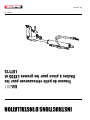
Wallenstein BA201 Back Hoe Kit Guide d'installation
- Taper
- Guide d'installation

Rev Sep-2021
INSTALLATION INSTRUCTIONS
Backhoe Kit for LXT95 & LXT115
Log Grapple Booms
BA
201
Z97831_En

2
BA201
Safety
Safety Alert Symbol
This Safety Alert Symbol means:
ATTENTION! BE ALERT!
YOUR SAFETY IS INVOLVED!
The Safety Alert Symbol identifies important safety messages
on the machine and in this instruction. This symbol means
be alert to the possibility of personal injury or death. Follow
instructions provided.
Signal Words
The signal words DANGER, WARNING and CAUTION determine
the seriousness level of the warning messages in this manual.
The appropriate signal word for each message in this manual
has been selected using the following guidelines:
DANGER –
Indicates an imminently hazardous situation that, if not avoided,
will result in death or serious injury. This signal word is to be
limited to the most extreme situations typically for machine
components which, for functional purposes, cannot be guarded.
WARNING –
Indicates a potentially hazardous situation that, if not avoided,
could result in death or serious injury, and includes hazards that
are exposed when guards are removed. It may also be used to
alert against unsafe practices.
CAUTION –
Indicates a potentially hazardous situation that, if not avoided,
may result in minor or moderate injury. It may also be used to
alert against unsafe practices.
IMPORTANT – To avoid confusing equipment protection with
personal safety messages, a signal word IMPORTANT indicates
a situation that if not avoided, could result in damage to the
machine.
Equipment Operation
WARNING!
Avoid the risk of personal injury or machine
damage! Read the operator’s manual before
using this equipment. Carefully read all safety
messages in the manual and follow all safety
signs on the machine.

3
BA201
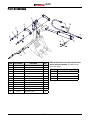
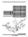
Parts Breakdown
5
7
10
9
1
3
2
8
12
8
6
11
4
Item Part Number Description Qty
1 3011C107 Cylinder, 2-1/4 x 12-7/8" Stroke 1
SLK-2212 Seal Kit for 3011C107 1
2 3011M109 Pin, 1 x 7.45 Greasable 2
3 3011M110 Pin, 1" x 5.66 Greasable 1
4 3011W102 RH Bucket Linkage 2
5 3011W103 Middle Bucket Linkage 1
6 3011W117 Bucket Pin w/ Washer 2
7 6089W250 Chain Hook 1
8 Z29202 Grease Fitting, 1/4NF 5
9 Z51917 Quick Coupler, FP04 x M ISO 5675 2
10 Z52261 3/8" Hose, FJIC06 x MP04 x 30" 2
11 Z71120 Hex Bolt, 1/4NC x 2" 5
12 Z72211 Hex Lock Nut, 1/4NC 5
BA201 Backhoe Kit does not include a bucket. Bucket
must be purchased separately. See table below for
bucket size options.
Model Size
BK2690 9" (23 cm) 3-tooth Bucket
BK2612 12" (30 cm) 3-tooth bucket
BK2615 15" (38 cm) 4-tooth bucket
BK2618 18" (46 cm) 4-tooth bucket

4
BA201
Installation Instructions
CAUTION!
Risk of a hazardous situation if kit is installed
improperly or modifi ed in any way. Damage to
the machine could result. Read and follow all
installation and setup instructions.
W091
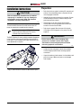
To install the BA201 Backhoe Kit and BK bucket on the LXT
boom, the grapple/rotor assembly must be removed.
Installation and operation of BA201 Kit is the
same for both the LXT95 and LXT115 booms.
All bucket sizes mount the same way.
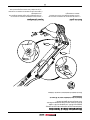
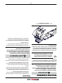
The BA201 Backhoe Kit comes partially assembled. Illustrations
in this instruction show a typical installation with the BK2612
bucket option. Once assembled, only regular maintenance and
minor adjustments are required.
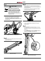
Fig. 1 – BA201 Backhoe Kit installed with BK2612 Bucket Option
Preparation
• Basic shop tools are required, including 3/8" wrenches and
sockets. An overhead lifting device is required to lift and
move the grapple and bucket.
• Hydraulic lines are disconnected in this procedure. Prepare
to catch fluid drips and have a container handy to store
parts that have been removed.
• Park the trailer on dry level ground, with the wheels
chocked. Make sure the log grapple trailer and the area
around it is clear and free of debris.
• Fully close the grapple. Move the boom off to the side
of the trailer and set the grapple on the ground. Shut the
engine off.
WARNING!
Risk of serious injury from escaping high-
pressure oil. Actuate controls after engine
shut down to relieve trapped pressure before
loosening hydraulic connections.
W080
• Actuate the boom and grapple controls after shutdown
to relieve trapped pressure before loosening hydraulic
connections.
• Unpack the backhoe kit and compare it to the hardware and
parts list on page 3. Make sure parts are not damaged
from shipping.

5
BA201
Step 1
CAUTION!
Risk of burns to exposed skin.
Hydraulic oil becomes hot during
operation. Hoses, lines, and other
parts become hot as well. Wait for
the oil and components to cool
before starting any maintenance or
inspection work.
W028
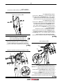
• Disconnect the four hydraulic lines from the quick
disconnects on the dipper boom. To prevent fluid
contamination, wrap the ends with a clean cloth or install
connector covers.
Fig. 2 – Quick Disconnects on Dipper Boom
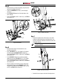
Step 2
• Remove the four hose clamps (two per side) to free up the
grapple hydraulic lines.
Fig. 3 – Hose Clamps
Step 3
• On the grapple pivot, remove the nut from the pivot pin.
Gently drive the pin out of the pivot. Move the grapple pivot
out of the boom nose.
• Reassemble the pin and nut to the grapple pivot. (Make
sure the two bushings remain inside.)
Fig. 4 – Grapple Pivot Pin
• Set the complete grapple assembly aside. Coil up the
hydraulic hoses.
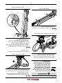
Step 4
1. Install 3011C107 Bucket Hydraulic Cylinder (1). Line up
the cylinder end bushing to the cylinder attach point on the
dipper arm.
• Insert 3011M110 pin (3). Secure with Z71120 1/4"NC x 2"
Hex bolt (11) and Z72211 Hex Locknut (12).
1
3
12
11
Fig. 5 – Install Bucket Cylinder

6
BA201
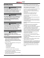
Step 5
• Install the bucket (purchased separately). Align the bucket
main pivot to the dipper main pivot.
• Position the 6089W250 chain hook (7) with the dipper
main pivot.
• Insert 3011W1170 flanged pin (6) through dipper, chain
hook, and pivot.
• Secure with Z71120 1/4"NC x 2" Hex bolt (11) and Z72211
Hex Locknut (12).
6
11
12
7
Fig. 6 – Install Bucket
Step 6
• Install bucket tilt linkage. Fit the bucket link into the
secondary bucket pivot.
• Insert a 3011W109 1.0" x 7.45" Flanged Pin (2) through
secondary pivot and 3011W103 Middle Linkage (5).
Secure with Z71120 1/4"NC x 2" Hex bolt (11) and Z72211
Hex Locknut (12).
• Fit the 3011W102 Linkage Arms (4) to the secondary
dipper pivot, then insert 3011W170 1.0" x 7.45" Flanged
Pin (6) through secondary dipper pivot and link arms.
Secure with Z71120 1/4"NC x 2" Hex bolt (11) and Z72211
Hex Locknut (12).
• Align the cylinder rod end bushing, the two linkage arms,
and the bucket linkage. Insert a 3011W170 1.0" x 7.45"
Flanged Pin (6), and secure with Z71120 1/4"NC x 2" Hex
bolt (11) and Z72211 Hex Locknut (12).
4
12 11
2
5
6
Fig. 7 – Installing Tilt Linkage
Step 7
• Connect the hydraulic hoses. Each hose is color-coded
to match the quick disconnects on the dipper boom, e.g.,
red to red, white/red to white/red. Connect each hose to its
appropriate color tag.
Hoses with blue tags are not used on the
backhoe installation.
10
9
Fig. 8 – Quick-disconnect Hoses
• Reinstall the hose clamps on the side of the dipper boom.

7
BA201
Operating Safety
WARNING!
Do not operate the machine until you are
thoroughly familiar with the position and function
of the various controls. Read the operator’s
manual thoroughly. Your safety is involved!
W065
WARNING!
Do operate the machine when not attached to
a tow vehicle. Machine could tip over causing
serious injury or death. Keep tow vehicle
attached and lower stabilizers fi rmly to the
ground for stability.
W097
WARNING!
Electrocution Hazard. Be aware of overhead
or underground power lines. Stay at least 20 ft
(6 m) or more away. Serious injury or death
could occur from electrocution. Electrocution is
possible without direct contact (arcing).
W015
WARNING!
Underground utility hazard. Contact an
underground utility locating and marking service
before digging.
W017
• Please remember it is important that you read the
operator's manual and heed the safety signs on the
equipment. They are there for your safety, as well as the
safety of others. The safe use of this machine is strictly up
to you, the operator.
• Before moving, making, adjustments or servicing, put the
machine in safe condition:
-install boom pin lock
-shut off the engine
-turn fuel valve off
-ensure boom is in safe position
-secure the tow vehicle / trailer from movement
• Review Safety Section in the operator's manual to set up
the operator Safe Zone and Work Zone.
• Position the trailer to provide a firm base for the stabilizer
pads before beginning excavation.
• Extend stabilizers to support frame while excavating.
• Keep the unit attached to the tow vehicle for extra stability.
• Review the work site and plan the project before starting,
clearly marking the area to be excavated.
• To avoid cave-in hazards, keep stabilizer and trailer tires at
least 3 ft (1 m) away from the edge of the trench.
• Have the area surveyed for underground utilities before
starting to dig.
• Stay at least 20 ft (6 m) away from power lines.
Electrocution can occur without direct contact.
• Do not allow riders or move or carry people on this
machine at any time.
• Be aware of your operator Safe Zone. Keep bucket, boom
and material outside of it.
• Keep all bystanders out of the Work Zone, at least 20 feet
(6 m) feet away from trailer and boom while excavating or
when engine is operating.
• Position the controls and operate the machine opposite the
Work Zone.
• Do not operate the engine inside a closed building.
Asphyxiation can occur from engine exhaust.
• Do not walk or work under a raised machine or attachment.
It is potentially hazardous to depend on the hydraulic
system to hold the machine or attachment in place.
• Never consume alcoholic beverages or drugs which hinder
alertness or coordination while operating this equipment.
Consult your doctor about operating this machine while
taking prescription medications.
• Stay away from overhead utilities and obstructions.
• Never allow children or unauthorized people to operate or
be around this machine.
• Keep hydraulic lines and fittings tight, free of leaks, in good
condition and clean.
• Keep the working area clean and free of debris to prevent
tripping. Operate only on level ground.
• When operating this equipment, it is recommended to have
at least two operators present and trained in safe operation
of the machine. All operators must be completely familiar
with all components of the machine and their function.
• Review safety instructions before each use or at least
annually.

8
BA201
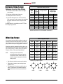
Controls
The main control valve has five control levers. The two outer
levers control the position of the stabilizers, and the other three
levers operate the main boom, dipper boom, and grapple.
With the BA201 Backhoe Kit installed, bucket curl-in and
curl-out is performed with the left-to-right grapple rotate control
lever (4). Grapple open/close lever (3) is not used.
01623
1
2 3 4
5
6
Fig. 9 – Main Directional Control Valve
1. Left-hand Stabilizer Raise/Lower
2. Main Boom Raise/Lower, Rotate
3. (Not used with Backhoe Kit)
4. Dipper Boom Raise/Lower, Bucket Curl-in/Curl-out
5. Right-hand Stabilizer Raise/Lower
6. Control Valve Function Decal
1. Left-hand Stabilizer
Stabilizer lower–push the lever forward to
lower the stabilizer.
Stabilizer raise–pull the lever back to raise
the stabilizer.
2. Main Boom Raise/Lower, Rotate
Main boom lower–push the lever forward to
lower the main boom.
Main boom raise–pull the lever back to raise
the main boom.
Main boom rotate left–push the lever
to the left to rotate the main boom
counterclockwise .
Main boom rotate right–push the lever to the
right to rotate the main boom clockwise.
3. Not used with Backhoe Kit
4. Dipper Boom Raise/Lower, Bucket Curl-in,
Curl-out
Dipper boom raise–push the lever forward to
raise the dipper boom.
Dipper boom lower–pull the lever back to
raise the dipper boom.
Bucket Curl-in–push the lever left to curl the
bucket in.
Bucket Curl-out–push the lever to curl the
bucket in.
5. Right-hand Stabilizer
Stabilizer lower–push the lever forward to
lower the stabilizer.
Stabilizer raise–pull the lever back to raise
the stabilizer.

9
BA201
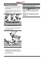
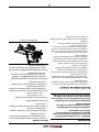
Digging with the Backhoe
• Swing the dipper out and adjust bucket so the teeth can dig
into the ground at a slight angle. Lower the boom down to
set teeth into the ground. Keep the heel of the bucket up
higher than the teeth.
• Retract the dipper to pull the bucket through the soil as it
fills. Slowly close the bucket at the same time. If necessary,
apply a downward pressure on the boom to increase
digging force.
00108
Fig. 10 – Digging with the Dipper Boom
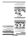
• Curl the bucket up when full. Raise the boom and at the
same time, move the dipper out a little to keep soil from
building up under the machine.
00109
Fig. 11 – Digging with Bucket
• Swing away from your excavation and dump the bucket.
Start dumping as the bucket approaches the pile. Do not
waste time by dumping too far from the excavation. Swing
back to start the next dig.
• Deepen the dig with each pass.
IMPORTANT! Do not use the side of the excavation to stop
the bucket. The backhoe could be damaged.
CAUTION!
Operation Hazard! Under certain conditions it
is possible to contact the stabilizers with the
bucket.
Always be aware of the location of the bucket.
Maintain the 3 ft (1 m) safety zone around the
stabilizers.
W069

10
BA201
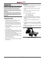
Transporting
IMPORTANT! LXT95 Log Loader / Trailer is not intended for
use or transport on public roadways. Therefore, it does not
include the required lights, reflectors, and markings.
Equipment that is transported on a public roadway must
comply with local laws that govern the safety and transport
of machinery.
Before taking this machine on a public roadway, make sure
it has the lighting, reflectors and markings required by your
local transportation authority. Make sure they are in good
working order.
Transporting Safety
• Comply with state and local laws governing safety and
transporting of machinery on public roads.
• Check that all the lights, reflectors and other lighting
requirements are installed and in good working condition.
• Do not exceed a safe travel speed. Slow down for rough
terrain and cornering.
• Place the boom and bucket in safe position before moving
or transporting.
• Do not drink and drive.
• Be sure the trailer is hitched positively to the tractor and a
retainer is used through the drawbar. Always attach safety
chains between the hitch and the tractor.
• Be a safe and courteous driver. Always yield to oncoming
traffic in all situations, including narrow bridges,
intersections, and so on. Watch for traffic when operating
near or crossing roadways.
• Never allow riders on the machine.
• Review the transport safety section of the LXT Log Loader
operator's manual.
Trailer mount
1. Be sure the trailer is hitched positively to the vehicle and a
retainer is used through the drawbar.
2. Maneuver the boom and rest the bucket in the dump box /
trailer.
3. Install the boom swing pin and secure with its retainer.
4. Retract the drop leg jack.
5. Do not exceed maximum load capacity:
• LT 30 – 5000 lb (2267 kg)
• LT 60 – 10,000 lb (4536 kg)
6. When transporting by highway, make sure a SMV sign is
attached, and reflectors are installed and in good working
condition.
7. Check that trailer brakes (if equipped) are functioning
properly.
8. Check your tow vehicle can accept ball hitch size (LXT95 –
2", LXT115 – 2-5/16"). Install retainer through the ball hitch
latch.
9. LXT115 articulating drawbar: make sure drawbar is straight
and drawbar pin is installed.
Fig. 12 – Trailer-mounted Boom

11
BA201
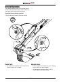
Service Illustration
This illustration shows the location of service grease points for
BA-201 and BK series buckets. BK-2612 bucket is shown, but
grease points are the same for all BK series buckets.
Grease pivot pins every 50 hours of operation.
Follow the maintenance schedule in the operator's manual.
Bucket Teeth
• The bucket teeth are replaceable. Check condition weekly.
Replace if chipped, bent, or damaged.
Hydraulic Hoses
• Check the condition of all hydraulic lines, hoses, and fittings
each use. Replace any that are damaged.
• Re-route hoses that are chafed, rubbing, pinched, or
crimped. Tighten any fitting that is leaking.

12
BA201
Product Warranty
rev. Nov-2018
LIMITED WARRANTY
Wallenstein products are warranted to be free of defects in materials and
workmanship under normal use and service, for a period of
Five Years for Consumer Use
Two Years for Commercial/Rental Use
from the date of purchase, when operated and maintained in accordance with the operang
and maintenance instrucons supplied with the unit. Warranty is limited to the repair of the
product and/or replacement of parts.
This warranty is extended only to the original purchaser and is not transferable.
Repairs must be done by an authorized dealer. Products will be returned to the dealer at the
customer’s expense. Include the original purchase receipt with any claim.
This warranty does not cover the following:
1) Normal maintenance or adjustments
2) Normal replacement of wearable and service parts
3) Consequen damage, indirect damage, or loss of prots
4) Damages resulng from:
• Misuse, negligence, accident, the or re
• Use of improper or insucient fuel, uids or lubricants
• Use of parts or aermarket accessories other than genuine Wallenstein parts
• Modicaons, alteraon, tampering or improper repair performed by pares other
than an authorized dealer
• Any device or accessories installed by pares other than an authorized dealer
5) Engines. Engines are covered by the manufacturer of the engine for the warranty period
they specify. For the details of your engine warranty, see your engine owner’s manual.
Informaon about engine warranty and service is also available in the FAQ secon at
www.wallensteinequipment.com

13
BA201
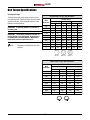
Bolt Torque Specications
Checking Bolt Torque
The tables shown give correct torque values for various
bolts and capscrews. Tighten all bolts to the torque values
specified in the table, unless indicated otherwise. Check
tightness of bolts periodically.
IMPORTANT! If replacing hardware, use fasteners of
the same grade.
IMPORTANT! Torque figures indicated in the table are
for non-greased or non-oiled threads. Do not grease or
oil threads unless indicated otherwise. When using a
thread locker, increase torque values by 5%.
NOTE: Bolt grades are identified by their head
markings.
Imperial Bolt Torque Specifi cations
Bolt
Diameter
Torque Value
SAE Gr. 2 SAE Gr. 5 SAE Gr. 8
lbf•ft N•m lbf•ft N•m lbf•ft N•m
1/4" 6 8 9 12 12 17
5/16" 10 13 19 25 27 36
3/8" 20 27 33 45 45 63
7/16" 30 41 53 72 75 100
1/2" 45 61 80 110 115 155
9/16" 60 95 115 155 165 220
5/8" 95 128 160 215 220 305
3/4" 165 225 290 390 400 540
7/8" 170 230 420 570 650 880
1" 225 345 630 850 970 1320
Metric Bolt Torque Specifi cations
Bolt
Diameter
Torque Value
Gr. 8.8 Gr. 10.9
lbf•ft N•m lbf•ft N•m
M3 0.4 0.5 1.3 1.8
M4 2.2 3 3.3 4.5
M6 7 10 11 15
M8 18 25 26 35
M10 37 50 52 70
M12 66 90 92 125
M14 83 112 116 158
M16 166 225 229 310
M20 321 435 450 610
M30 1,103 1 495 1,550 2 100

14
BA201
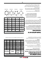
Hydraulic Fitting Torque
Tightening Flare Type Tube Fittings
1. Check flare and flare seat for defects that might
cause leakage.
2. Align tube with fitting before tightening.
3. Hand-tighten swivel nut until snug.
4. To prevent twisting the tube, use two wrenches.
Place one wrench on the connector body and tighten
the swivel nut with the second. Torque to values
shown.
If a torque wrench is not available, use the FFFT (Flats
From Finger Tight) method.
Hydraulic Fitting Torque
Tube
Size
OD
Hex
Size
Across
Flats
Torque value Flats From
Finger Tight
Inches Inches lbf•ft N•m Flats Turns
3/16 7/16 6 8 2 1/6
1/4 9/16 11–12 15–17 2 1/6
5/16 5/8 14–16 19–22 2 1/6
3/8 11/16 20–22 27–30 1-1/4 1/6
1/2 7/8 44–48 59–65 1 1/6
5/8 1 50–58 68–79 1 1/6
3/4 1-1/4 79–88 107–119 1 1/8
1 1-5/8 117–125 158–170 1 1/8
Values shown are for non-lubricated connections.
Wheel Lug Torque
It is extremely important safety procedure to apply and
maintain proper wheel mounting torque on your trailer
axle. Torque wrenches are the best method to assure the
proper amount of torque is being applied to a fastener.
Wheel lugs should be torqued before first road use and
after each wheel removal. Check and re torque after the
first 10 miles (16 km), 25 miles (40 km), and again at
50 miles (80 km). Check periodically thereafter.
NOTE: Wheel lugs must be applied and
maintained at the proper torque levels to
prevent loose wheels, broken studs, and
possible dangerous separation of wheels
from your axle.
• Start all lugs by hand to prevent cross threading.
• Tighten lugs in sequence, per wheel lug torque
sequence chart.
• The tightening of the fasteners should be done in
stages. Following the recommended sequence,
tighten fasteners per wheel torque requirements
chart.
Wheel Lug Nut Torque
Wheel
Size Units 1st Stage 2nd Stage 3rd Stage
8" lbf•ft
N•m
12–20
16–26
30–35
39–45.5
45–55
58.5–71.5
12" lbf•ft
N•m
20–25
26–32.5
35–40
45.5–52
50–60
65–78
13" lbf•ft
N•m
20–25
26–32.5
35–40
45.5–52
50–60
65–78
14" lbf•ft
N•m
20–25
26–32.5
50–60
65–78
90–120
117–156
15" lbf•ft
N•m
20–25
26–32.5
50–60
65–78
90–120
117–156
16" lbf•ft
N•m
20–25
26–32.5
50–60
65–78
90–120
117–156
4-Bolt
Wheel Lug Torque Pattern
5-Bolt 6-Bolt 8-Bolt

14
BA201
Couple appliqué aux
raccords hydrauliques
Serrage des raccords coniques de tube
1. Vérifiez l’évasement et le logement de l’évasement
pour repérer la présence éventuelle de défauts qui
peuvent causer une fuite.
2. Alignez le tube sur le raccord avant de serrer.
3. Serrez à fond l’écrou orientable jusqu’à ce qu’il soit
bien serré.
4. Pour éviter de tordre le tube, utilisez deux clés.
Placez une des clés sur le bâti du connecteur et
serrez l’écrou orientable avec la deuxième clé selon
le couple indiqué. Serrez au couple selon les valeurs
indiquées.
Si vous n’avez pas de clé dynamométrique, utilisez la
méthode FFFT (Plaques avec serrage manuel).
Couple appliqué sur les
écrous de roue
À des fins de sécurité, il est extrêmement important
d’appliquer et de maintenir un couple de serrage des
roues approprié sur l’essieu de la remorque. Les clés
dynamométriques sont l’outil idéal pour s’assurer que le
couple approprié est appliqué à une fixation.
Les écrous de roue doivent être serrés au couple avant la
première utilisation sur la route et chaque fois qu’une roue
a été enlevée. Vérifiez et resserrez au couple au bout des
premiers 16 km (10 milles), 40 km (25 milles) et encore
après 80 km (50 milles). Vérifiez périodiquement par la
suite.
REMARQUE : Le couple des écrous de roue doit être
maintenu correctement afin d’éviter le
desserrement des roues, la cassure des
pivots et peut-être même une séparation
dangereuse des roues de l’essieu.
• Serrez d’abord tous les écrous à la main pour ne pas
fausser le filetage.
• Serrez les écrous de roue l’un après l’autre, dans l’ordre
indiqué dans le tableau de séquence du serrage au couple
des écrous de roue.
• Le serrage des fixations doit être fait par étapes. En suivant
l’ordre recommandé, serrez les fixations conformément au
tableau des exigences du serrage au couple des roues.
Couple appliqué sur les raccords hydrauliques
Diamètre
extérieur
du tube
Taille des
écrous
hexagonaux
à travers les
plaques
Couple de
serrage Plaques avec
serrage manuel
Pouces Pouces lb•pi N•m Plaques Tours
3/16 7/16 6 8 2 1/6
1/4 9/16 11-12 15-17 2 1/6
5/16 5/8 14-16 19-22 2 1/6
3/8 11/16 20-22 27-30 1-1/4 1/6
1/2 7/8 44-48 59-65 1 1/6
5/8 1 50-58 68-79 1 1/6
3/4 1-1/4 79-88 107-119 1 1/8
1 1-5/8 117-125 158-170 1 1/8
Les valeurs indiquées s’appliquent aux raccords non lubrifi és.
Couple appliqué sur les écrous de roue
Dimensions
des roues Unités 1er stade 2e stade 3e stade
8 po lb•pi
N•m
12-20
16-26
30-35
39-45,5
45-55
58,5-71,5
12 po lb•pi
N•m
20-25
26-32,5
35-40
45,5-52
50-60
65-78
13 po lb•pi
N•m
20-25
26-32,5
35-40
45,5-52
50-60
65-78
14 po lb•pi
N•m
20-25
26-32,5
50-60
65-78
90-120
117-156
15 po lb•pi
N•m
20-25
26-32,5
50-60
65-78
90-120
117-156
16 po lb•pi
N•m
20-25
26-32,5
50-60
65-78
90-120
117-156
4 boulons
Séquence de serrage au couple des écrous de roue
5 boulons 6 boulons 8 boulons

13
BA201
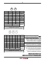
Spécications relatives au couple
de serrage des boulons
Vérification du couple appliqué sur les boulons
Les tableaux figurant ci-dessous donnent les valeurs
correctes de couple pour divers boulons et vis
d'assemblage. Serrez tous les boulons selon le couple
spécifié dans le tableau, sauf mention contraire. Vérifiez
de temps à autre que les boulons sont bien serrés.
IMPORTANT! Si vous remplacez de la quincaillerie,
utilisez des fixations de la même catégorie.
IMPORTANT! Les valeurs de couple de serrage
indiquées dans le tableau s’appliquent aux filets non
graissés et non huilés. Ne pas graisser ou huiler les
filets, sauf mention contraire. Lorsque vous utilisez un
enduit frein pour filets, augmentez la valeur de couple
de 5 %. Les catégories des boulons sont indiquées sur
leur tête.
Spécifi cations relatives au couple de serrage des
boulons en unités impériales
Diamètre
du
boulon
Couple de serrage
SAE Gr. 2 SAE Gr. 5 SAE Gr. 8
lb•pi N•m lb•pi N•m lb•pi N•m
1/4 po 6 8 9 12 12 17
5/16 po 10 13 19 25 27 36
3/8 po 20 27 33 45 45 63
7/16 po 30 41 53 72 75 100
1/2 po 45 61 80 110 115 155
9/16 po 60 95 115 155 165 220
5/8 po 95 128 160 215 220 305
3/4 po 165 225 290 390 400 540
7/8 po 170 230 420 570 650 880
1 po 225 345 630 850 970 1 320
Spécifi cations relatives au couple de serrage des
boulons en unités métriques
Diamètre
du boulon
Couple de serrage
Gr. 8,8 Gr. 10,9
lb•pi N•m lb•pi N•m
M3 0,4 0,5 1,3 1,8
M4 2,2 3 3,3 4,5
M6 7 10 11 15
M8 18 25 26 35
M10 37 50 52 70
M12 66 90 92 125
M14 83 112 116 158
M16 166 225 229 310
M20 321 435 450 610
M30 1 103 1 495 1 550 2 100

12
BA201
Garantie sur le produit
rev. Nov 2018
GARANTIE LIMITÉE
Les produits Wallenstein sont garan contre tous défauts de matériaux et de fabricaon dans
des condions normales d’usaon et de service, pour une période de
Cinq Ans pour usage domesque
Deux Ans pour usage commercial/locaon
à parr de la date d’achat, lorsqu’ils sont ués et entretenus conformément aux instrucons
d’usaon et d’entreen fournies avec l’unité. La garane est limitée à la réparaon du
produit et/ou au remplacement des pièces.
Cee garane est applicable uniquement à l’acheteur d’origine et n’est pas transférable.
Les réparaons doivent être faite par un concessionnaire autorisé. Les produits doivent être
retournés chez le concessionnaire au frais du client. Inclure une copie de la facture d’achat
original avec toute réclamation.
Cee garane ne couvre pas ce qui suit :
1) Maintenance normale ou ajustements
2) Remplacement normal des pièces d’usure et de service
3) Dommages consécufs, dommages indirects, ou perte de prots
4) Dommage résultant de:
• Abus, négligence, accident, vol ou feu
• Usaon de carburant, de liquides ou de lubriants inappropriés ou insusants
• Usaon de pièces ou d’accessoires de rechange autres que les pièces d’origine
Wallenstein
• Modicaons, altéraons ou réparaons inappropriées eectuées par des pares
autres qu’un concessionnaire autorisé
• Tout appareil ou accessoire installé par des ers autres qu’un concessionnaire
autorisé
5) Moteurs. Les moteurs sont couverts par le fabricant du moteur pour la période de
garane spéciée. Pour plus de détails sur la garane de votre moteur, consultez le
manuel du propriétaire de votre moteur. Des informaons à propos de la garane et le
service du moteur sont également disponibles dans la secon FAQ du site
www.wallensteinequipment.com

11
BA201
Illustrations liées à l’entretien
Cette illustration présente l'emplacement des points de graissage
d'entretien pour BA-201 et les godets de série BK. Le godet
BK-2612 est illustré, mais les points de graissage sont de série
est le même pour tous les godets de série BK.
Graissez les tiges d'articulation toutes les 50 heures de
fonctionnement.
Suivez le calendrier d’entretien dans le manuel de l’utilisateur.
Dents du godet
• Les dents du godet peuvent être remplacées. Vérifiez leur état
toutes les semaines. Remplacez-les si elles sont ébréchées,
abîmées ou endommagées.
Tuyaux hydrauliques
• Vérifiez l’état de l’ensemble des conduites, des tuyaux et des
raccords hydrauliques après chaque utilisation. Remplacez toute
pièce endommagée.
• Déplacez les tuyaux qui subissent un frottement ou un pincement
ou qui sont ondulés. Serrez tout raccord qui présente une fuite.

10
BA201
Transport
IMPORTANT! La grue forestière/remorque LXT95 n'est
pas conçue pour être utilisée ou transportée sur les routes
publiques. Par conséquent, il n’inclut pas les feux, les
réflecteurs et le marquage requis.
L’équipement transporté sur une route publique doit
respecter les lois locales relatives à la sécurité et au
transport de machines.
Avant d'apporter cette machine sur une route publique,
assurez-vous qu'elle dispose des feux, des réflecteurs et des
marquages requis par les autorités locales chargées des
transports. Assurez-vous qu'ils sont en bon état de marche.
Sécurité relative au transport
• Observez les lois et les règlements municipaux, provinciaux et
d’État relativement à la sécurité lors du transport de l’équipement
sur les chemins publics.
• Assurez-vous que l’ensemble des lampes, des réflecteurs et des
autres éléments exigés relativement à l’éclairage sont installés et
en bon état de fonctionnement.
• Ne dépassez pas la vitesse jugée sécuritaire. Ralentissez lorsque
la surface de la route est mauvaise et lors des virages.
• Mettez la flèche et le godet en position sécuritaire avant le
déplacement ou le transport.
• Ne conduisez pas si vous avez consommé de l'alcool.
• Assurez-vous que l'équipement est bien accouplé au tracteur et
qu'un dispositif de retenue est inséré au travers de la barre de
remorquage. Attachez toujours des chaînes de sécurité entre
l’attelage et le tracteur.
• Soyez courtois au volant et conduisez prudemment. Cédez
toujours le passage à la circulation qui vient vers vous, y compris
notamment sur les ponts étroits et aux intersections. Surveillez la
circulation lorsque vous travaillez à proximité de la chaussée ou
lorsque vous traversez celle-ci.
• Ne laissez aucun passager se déplacer avec vous sur
l'équipement.
• Consultez la section sur la sécurité relative au transport du manuel
de l’utilisateur de la grue forestière LXT.
Fixation sur remorque
1. Assurez-vous que la remorque est attelée correctement au
véhicule remorqueur et qu'un dispositif de retenue traverse
le coupleur de l'attelage.
2. Manœuvrez la flèche et reposez le godet dans la benne de
déchargement ou la remorque.
3. Installez la tige de pivot de la flèche et fixez-la à l'aide de sa
pièce de retenue.
4. Rentrez la chandelle de fixation.
5. Ne dépassez pas la capacité de charge maximale :
• LT 30 – 5 000 lb (2 267 kg)
• LT 60 – 10 000 lb (4 536 kg)
6. Lors du transport sur la route, assurez-vous qu'un écriteau
Véhicule lent est posé et que les réflecteurs sont installés et
en bon état de fonctionnement.
7. Vérifiez que les freins de remorque (s’ils sont présents)
fonctionnent correctement.,
8. Vérifiez que votre véhicule de remorquage peut accepter
la taille de la rotule d'attelage (LXT95 – 2 po, LXT115 –
2-5/16 po). Insérez le dispositif de retenue au travers du
loquet de la rotule d’attelage.
9. Barre de remorquage articulée LXT115 : assurez-vous que
la barre de remorquage est droite et que la tige de la barre
de remorquage est installée.
Fig. 12 – Flèche sur remorque

9
BA201
Creusage à l’aide de la pelle
rétrocaveuse
• Faites pivoter le bras de manœuvre et ajustez le godet afin que
les dents puissent s’enfoncer dans le sol avec un léger angle.
Abaissez la flèche afin d’enfoncer les dents dans le sol. Le talon
du godet doit rester au-dessus des dents.
• Rentrez le bras de manœuvre afin de tirer le godet dans la terre
au fur et à mesure où il se remplit. En même temps, fermez
lentement le godet. Au besoin, appliquez une pression vers le bas
sur la flèche pour augmenter la force de creusage.
00108
Fig. 10 – Creusage à l’aide du bras de manœuvre du godet
• Repliez le godet lorsqu’il est plein. Relevez la flèche et en même
temps, sortez un peu le bras de manœuvre pour empêcher la terre
de s’accumuler sous la machine.
00109
Fig. 11 – Creusage à l’aide du godet
• Pivotez en vous éloignant de votre excavation et déchargez le
godet. Commencez à décharger le godet lorsqu’il s’approche de la
pile. Ne perdez pas de temps en déchargeant le godet trop loin de
l’excavation. Pivotez de nouveau pour recommencer à creuser.
• Approfondissez l’excavation avec chaque passage.
IMPORTANT! N’utilisez pas le côté de l’excavation pour
arrêter le godet. Cela pourrait endommager la pelle
rétrocaveuse.
ATTENTION!
Danger lié au fonctionnement! Dans certaines
conditions, il est possible que le godet entre en
contact avec les stabilisateurs.
Soyez toujours conscient de l’emplacement du
godet. Maintenez une zone de sécurité de 3 pi
(1 m) autour des stabilisateurs.
W069
La page est en cours de chargement...
La page est en cours de chargement...
La page est en cours de chargement...
La page est en cours de chargement...
La page est en cours de chargement...
La page est en cours de chargement...
La page est en cours de chargement...
La page est en cours de chargement...
-
 1
1
-
 2
2
-
 3
3
-
 4
4
-
 5
5
-
 6
6
-
 7
7
-
 8
8
-
 9
9
-
 10
10
-
 11
11
-
 12
12
-
 13
13
-
 14
14
-
 15
15
-
 16
16
-
 17
17
-
 18
18
-
 19
19
-
 20
20
-
 21
21
-
 22
22
-
 23
23
-
 24
24
-
 25
25
-
 26
26
-
 27
27
-
 28
28


Wallenstein BA201 Back Hoe Kit Guide d'installation
- Taper
- Guide d'installation
dans d''autres langues
Documents connexes
Autres documents
-
Wacker Neuson ET65 Manuel utilisateur
-
-
-
-
-
-
-