
E(D/F)-M-RS12/24T-V1_00
Rotronic AG
Bassersdorf, Switzerland
Document code Unit
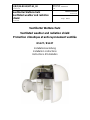
Ventilierter Wetterschutz
Ventilated weather and radiation
shield
Instruction Manual
Document Type
Page
1 of 17
Document title
Ventilierter Wetterschutz
Ventilated weather and radiation shield
Protection climatique et anti-rayonnement ventilée
RS12T / RS24T
Installationsanleitung
Installation instructions
Instructions d’installation

E(D/F)-M-RS12/24T-V1_00
Rotronic AG
Bassersdorf, Switzerland
Document code Unit
Ventilierter Wetterschutz
Ventilated weather and radiation
shield
Instruction Manual
Document Type
Page
2 of 17
Document title
Inhalt
1. Einführung........................................................................................................................ 3
2. Ausführungen................................................................................................................... 3
3. Wetterschutz RS12T / RS24T.......................................................................................... 3
4. Montagearme zu RS12T / RS24T.................................................................................... 4
5. Montage und Demontage................................................................................................. 5
6. Klemmenbelegung Wetterschutz / Montagearm (alle Typen).......................................... 7
7. Wartung und Kalibrierung................................................................................................. 7
8. Ersatzteile......................................................................................................................... 7
Contents
1. Introduction....................................................................................................................... 8
2. Models.............................................................................................................................. 8
3. Weather and Radiation Shields RS12T / RS24T.............................................................. 8
4. Mounting arms for RS12T / RS24T.................................................................................. 9
5. Mounting and removal...................................................................................................... 10
6. Terminal assignment (all Models)..................................................................................... 12
7. Maintenance and calibration............................................................................................. 12
8. Spare Parts....................................................................................................................... 12
Table de matières
1. Introduction..................................................................................................................... 13
2. Modèles.......................................................................................................................... 13
3. Protection climatique anti-rayonnement RS12T / RS24T............................................... 13
4. Dispositif de montage pour RS12T / RS24T.................................................................. 14
5. Montage et démontage................................................................................................... 15
6. Raccordements du bornier (tous les modèles)............................................................... 17
7. Maintenance et étalonnage............................................................................................ 17
8. Pièces détachées........................................................................................................... 17

E(D/F)-M-RS12/24T-V1_00
Rotronic AG
Bassersdorf, Switzerland
Document code Unit
Ventilierter Wetterschutz
Ventilated weather and radiation
shield
Instruction Manual
Document Type
Page
3 of 17
Document title
1. Einführung
Der ventilierte Wetter- und Strahlungsschutz RS12T mit 12 VDC Ventilator bzw. RS24T mit 24
VDC Ventilator wurde in enger Zusammenarbeit mit MeteoSchweiz entwickelt. Es handelt sich
dabei um ein dem neuesten Stand der Technik entsprechendes Gerät, welches die Einflüsse
thermischer Strahlung auf die Feuchte- und Temperaturmesswerte auf ein Minimum reduziert. Der
Schirm bietet aber auch optimalen Schutz bei stürmischem Wetter, selbst gegen horizontal
einfallenden Niederschlag. Die in der Kombination des neuen Schirms und der ROTRONIC
Meteorologiefühler gemessenen Werte sind praktisch identisch mit denen der viel teureren
Taupunktspiegel, welche in vielen nationalen Organisationen als Referenzgeräte eingesetzt
werden. Der Ventilator wird über ein separates Kabel mit Spannung versorgt. Der Schild bietet
gegenüber den bisher verwendeten Produkten eine wesentliche Steigerung der Messwert-
Genauigkeit. Alle ROTRONIC Meteorologiefühler können mit dem neuen Schirm verwendet
werden.
2. Ausführungen
RS12T und RS24 sind abgesehen von der unterschiedlichen Versorgungsspannung für den
Ventilator absolut identisch.
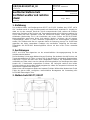
Die Geräte bieten Schutz gegen Niederschlag und Strahlung. Das bedeutet, dass die Feuchte- und
Temperaturverhältnisse am Fühler zu nahezu 100 % den tatsächlich vorhandenen Gegebenheiten
entsprechen. Erreicht wird dies durch einen zweigeteilten Luftstrom: Der Hauptluftstrom fliesst
rechtwinklig am Fühler vorbei, was eine optimale Anströmung bewirkt. Der Strahlungsschutz selber
besteht aus 2 übereinander angeordneten Schirmen. Die Luftschicht zwischen den beiden
Schirmen wird durch den Ventilator ständig ausgetauscht, sodass die Temperatur im Messrohr den
tatsächlichen Gegebenheiten entspricht.
Wetterschutz und Montagearme bilden zwei separate Einheiten. Während der Wetterschutz für alle
Fühler der gleiche bleibt, ermöglichen unterschiedliche Montagearme die Verwendung aller
ROTRONIC Meteorologie-Fühler.
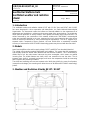
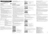
3. Wetterschutz RS12T / RS24T

E(D/F)-M-RS12/24T-V1_00
Rotronic AG
Bassersdorf, Switzerland
Document code Unit
Ventilierter Wetterschutz
Ventilated weather and radiation
shield
Instruction Manual
Document Type
Page
4 of 17
Document title
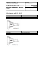
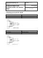
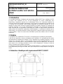
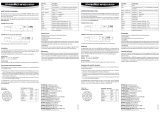
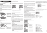
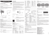
4. Montagearme zu RS12T / RS24T
Best.-Nr.
MKRS-HC2
Verwendung mit
HC2-S3 / S3H
Fühleranschluss
E2 Stecker
Mastdurchmesser
30-65 mm
Best.-Nr.
MKRS-MP102-402
Verwendung mit
MP102H / 402H
Fühleranschluss
Offene Enden auf Klemmen
Mastdurchmesser
30-65 mm

E(D/F)-M-RS12/24T-V1_00
Rotronic AG
Bassersdorf, Switzerland
Document code Unit
Ventilierter Wetterschutz
Ventilated weather and radiation
shield
Instruction Manual
Document Type
Page
5 of 17
Document title
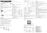
5. Montage und Demontage
Die Wetterschutzschilde, Fühler und Montagearme werden immer separat geliefert.
Montieren Sie die einzelnen Teile wie folgt:
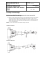
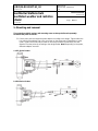
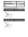
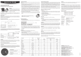
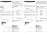
5.1 Stecken Sie den Fühler gemäss Zeichnung in den Fühleradapter und ziehen Sie entweder
die Inbusschraube am Adapterring oder die beiden Stellschrauben am Rohr (je nach
Adapter und Fühler) an. Ziehen Sie die Schrauben nur so stark an, dass der Fühler sicher
gehalten wird. Beachten Sie insbesondere die richtige Distanz von der Fühlerspitze zum
Flansch des Adapterringes.
Hinweis: Je nach Fühler werden unterschiedliche Adapter verwendet.
a. Fühler der HC2-Serie
b. Fühler der MPH-Serie

E(D/F)-M-RS12/24T-V1_00
Rotronic AG
Bassersdorf, Switzerland
Document code Unit
Ventilierter Wetterschutz
Ventilated weather and radiation
shield
Instruction Manual
Document Type
Page
6 of 17
Document title
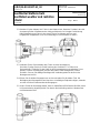
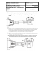
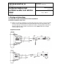
5.2 Montieren Sie den Adapter inkl. Fühler in den Wetterschutz. Beachten Sie dabei, dass die
Aussparung für den Ventilatorstecker richtig positioniert ist. Bei richtiger Positionierung
bilden Adapterring und Flansch eine ebene Fläche. Der Adapter wird von zwei
Kugelsperren festgehalten; es ist nicht notwendig ihn mit Schrauben zu fixieren.
5.3 Verbinden Sie die Steckverbinder des Fühlers und des Montagearms.
Der kleine 2-polige Stecker ist für die Speisung des Ventilators. Für Fühler ohne
Steckverbinder: Schlaufen Sie das Kabel in den Klemmenkasten und verdrahten Sie es
gemäss Schema. Die Aderfarben sind auf dem jedem Fühler beiliegenden Schema
ersichtlich. Stossen Sie allfällige Überlängen der Verbindungskabel in das Rohr des
Montagearmes zurück.
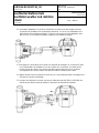
5.4 Richten Sie die beiden Baugruppen aus und verschrauben Sie die beiden Teile. Die
Befestigung des Montagearmes am Mast kann zu beliebigem Zeitpunkt erfolgen, entweder
vor oder nach dem Zusammenbau der Baugruppen
5.5 Achten Sie bei der Demontage darauf, dass ein Kabelfühler (MP102Hoder MP402H) zuerst
im Klemmenkasten abgehängt wird. Erst danach die Verbindung zwischen Wetterschutz
und Montagearm lösen

E(D/F)-M-RS12/24T-V1_00
Rotronic AG
Bassersdorf, Switzerland
Document code Unit
Ventilierter Wetterschutz
Ventilated weather and radiation
shield
Instruction Manual
Document Type
Page
7 of 17
Document title
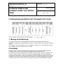
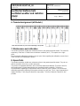
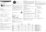
6. Klemmenbelegung Wetterschutz / Montagearm (alle Typen)
7. Wartung und Kalibrierung
Die Wetterschutzschilde sind weitestgehend wartungsfrei. Die mittlere Lebensdauer der
Ventilatoren beträgt bei Umgebungstemperatur (40 °C) 70'000 Stunden. Dies entspricht rund acht
Jahren.
Wir empfehlen, die Fühler einmal pro Jahr zu kalibrieren. Hinweise zur Fühlerkalibrierung sind in
den Unterlagen über die einzelnen Fühler zu finden.
8. Ersatzteile
Die Wetterschutz Schirme sind weitestgehend wartungsfrei und enthalten mit Ausnahme des
Ventilators keine Verschleissteile oder andere regelmässig zu ersetzende Teile.
Die Fühler sind mit Filtern ausgestattet, die periodisch ersetzt werden sollten. Der Zeitpunkt des
Ersatzes hängt wesentlich von den herrschenden Umweltbedingungen ab; eine Empfehlung
bezüglich des Intervalls kann daher nicht abgegeben werden. Dagegen empfehlen wir, die Fühler
mindestens ein Mal pro Jahr zu kalibrieren bzw. justieren. Bei dieser Gelegenheit können jeweils
die Filter ersetzt werden. Sie lassen sich in seifiger Lösung oder in Ultraschallgeräten reinigen.

E(D/F)-M-RS12/24T-V1_00
Rotronic AG
Bassersdorf, Switzerland
Document code Unit
Ventilierter Wetterschutz
Ventilated weather and radiation
shield
Instruction Manual
Document Type
Page
8 of 17
Document title
1. Introduction
The ventilated weather and radiation shields RS12T with 12 VDC fans and RS24T with 24 VDC
fans were developed in close cooperation with MeteoSwiss, the Swiss National Meteorological
Organisation. The instruments reduce the influence of thermal radiation on the measurements of
temperature and humidity to a minimum and represent state-of-the art technology. The shield also
offers optimum protection in stormy weather, even against horizontally driven rain and snow. The
values measured by the combination of the weather shields and a ROTRONIC meteorological
probe are practically identical to the ones measured by much more expensive dew point mirrors
used as reference instruments by many meteorological organisations. The fan is supplied by a
separate cable. Compared to former products, the new shield offers a remarkably increased
accuracy of measurement. All ROTRONIC Meteorology-probes may be used with the new shield.
2. Models
Apart from the different fan and its supply voltage, RS12T and RS24T are absolutely identical.
The shields offer protection against precipitation and radiation. This means that the temperature-
and humidity values are almost 100% identical with the effective conditions. This is achieved by a
divided flow of air: the main stream intersects the probe rectangular, which means an optimal
incoming flow. The shield features two shells, which are mounted one over the other. The air
between these shells is constantly exchanged, and hence the temperature inside the measuring
tube is equal to the prevailing conditions.
The shield and mounting arms are two separate units. While the shield ist he same for all probes,
(except fan and voltage), the mounting arms allow the use of all different ROTRONIC meteorology-
probes.
3. Weather and Radiation Shields RS12T / RS24T

E(D/F)-M-RS12/24T-V1_00
Rotronic AG
Bassersdorf, Switzerland
Document code Unit
Ventilierter Wetterschutz
Ventilated weather and radiation
shield
Instruction Manual
Document Type
Page
9 of 17
Document title
4. Mounting arms for RS12T / RS24T
Order code
MKRS-HC2
Use with
HC2-S3 / S3H
Probe connection
E2 connector
Mast diameter
30-65 mm
Order code
MKRS-MP102-402
Use with
MP102H / 402H
Probe connection
Open ends to terminals
Mast diameter
30-65 mm

E(D/F)-M-RS12/24T-V1_00
Rotronic AG
Bassersdorf, Switzerland
Document code Unit
Ventilierter Wetterschutz
Ventilated weather and radiation
shield
Instruction Manual
Document Type
Page
10 of 17
Document title
5. Mounting and removal
The protection shields, probes and mounting arms are always delivered separately.
Assemble the parts as follows:
5.1 Put the probe into the respective probe adaptor according to the design. Tighten either the
Hex screw of the adaptor ring or the set screws on the probe tube. (Depending on probe
used). Tighten the screws only as hard as necessary to hold the probe firmly. Set the
distance from the probe tip according to the design below. Note: Depending on the probe,
different adaptors are used.
a. HC2-Series Probes
b. MPH-Series Probes

E(D/F)-M-RS12/24T-V1_00
Rotronic AG
Bassersdorf, Switzerland
Document code Unit
Ventilierter Wetterschutz
Ventilated weather and radiation
shield
Instruction Manual
Document Type
Page
11 of 17
Document title
5.2 Assemble the adaptor, probe and weather protection shield. Make sure to position the slot
for the fan connector correctly. If positioned correctly, adaptor and flange form an even
surface. The adaptor must not be fixed by screws. Two ball-type locks fix the adaptor in its
position.
5.3 Join the connectors of the probe and mounting arm. The small two-pin connector serves for
the fan supply. For probes without plugs: Loop the cable into the connection box and wire
according to the schematics. The wire colours are mentioned on every schematic
accompanying the probes. Push a surplus length of cable back into the tube.
5.4 Align the two sub-assemblies and tighten the screws. Mounting onto the pole may be done
at any time; either before or after assembly.
.5 When disassembling, make sure that a cable probe (MP102H or MP402H) is disconnected
in the junction box before the screws between shield and mounting arms are removed.

E(D/F)-M-RS12/24T-V1_00
Rotronic AG
Bassersdorf, Switzerland
Document code Unit
Ventilierter Wetterschutz
Ventilated weather and radiation
shield
Instruction Manual
Document Type
Page
12 of 17
Document title
6. Terminal assignment (all Models)
7. Maintenance and calibration
The weather protection shields are maintenance-free to the greatest possible extent. The mean life
expectancy of the fans is 70.000 hours at ambient conditions (40 °C). This equals to ca. eight
years.
We recommend calibrating the probes once per year. Hints regarding the calibration may be found
in the manuals accompanying the probes.
8. Spare Parts
The weather protection shields are maintenance-free to the greatest possible extent. They do not –
with the exception of the fans- contain wear parts.
The probes are equipped with filters, which should be replaced periodically. The point in time for
their replacement is mainly determined by the prevailing ambient conditions. Therefore, a
recommendation regarding the replacement interval cannot be given. However, we recommend
calibrating respectively adjusting of the probes at least once per year. This is a good opportunity to
replace the filters. These may be cleaned in soapy water. The use of ultrasonic cleaners is also
possible.

E(D/F)-M-RS12/24T-V1_00
Rotronic AG
Bassersdorf, Switzerland
Document code Unit
Ventilierter Wetterschutz
Ventilated weather and radiation
shield
Instruction Manual
Document Type
Page
13 of 17
Document title
1. Introduction
Les nouvelles protections climatiques anti-rayonnement ventilées RS12T avec ventilateur 12 VCC
et RS24T avec ventilateur 24 VCC ont été développées en proche collaboration avec
MeteoSuisse, l'organisme national de la météorologie Suisse. Ces instruments réduisent au
maximum l'influence des radiations thermiques sur les mesures de température et humidité et sont
à la pointe de la technologie. L'abri constitue également une protection optimale en cas de
tempête, et même contre une pluie ou neige horizontale. Les valeurs mesurées en combinant une
protection climatique et une sonde météorologique ROTRONIC sont pratiquement identiques à
celles mesurées par un hygromètre à miroir bien plus coûteux et utilisé comme instrument de
référence dans de nombreuses organisations météorologiques. Le ventilateur est alimenté par un
câble séparé. Les nouvelles protections offrent une précision nettement meilleure par rapport à nos
anciens modèles. Toutes les sondes météo ROTRONIC peuvent être utilisées avec les nouvelles
protections.
2. Modèles
Ce qui différencie le modèle RS12T et RS24T c'est uniquement leur ventilateur et alimentation.
L'abri offre une protection contre les précipitations et les radiations. Ce qui signifie que les valeurs
de température et humidité sont presque à 100 % identiques aux conditions effectives. Ceci est
obtenu par un flux d'air divisé : le flux principal coupe la sonde perpendiculairement, ce qui
entraîne un flux d'entrée optimal. L'abri possède deux coques qui sont superposées. L'air entre ces
deux coques est en échange permanent, et de ce fait la température à l'intérieur du tube de
mesure correspond aux conditions ambiantes.
La protection et le dispositif de montage sont deux parties distinctes. Il y a deux types de protection
qui ne dépendent pas du type de sonde, alors que le dispositif de montage dépend lui du type de
sonde.
3. Protection climatique anti-rayonnement RS12T / RS24T

E(D/F)-M-RS12/24T-V1_00
Rotronic AG
Bassersdorf, Switzerland
Document code Unit
Ventilierter Wetterschutz
Ventilated weather and radiation
shield
Instruction Manual
Document Type
Page
14 of 17
Document title
4. Dispositif de montage pour RS12T / RS24T
N° de comm.
MKRS-HC2
Utilisation avec
HC2-S3 / S3H
Raccordement capteur
Connecteur E2
Diamètre du mât
30-65 mm
N° de comm.
MKRS-MP102-402
Utilisation avec
MP102H / 402H
Raccordement capteur
Extrémités ouvertes sur bornes
Diamètre du mât
30-65 mm

E(D/F)-M-RS12/24T-V1_00
Rotronic AG
Bassersdorf, Switzerland
Document code Unit
Ventilierter Wetterschutz
Ventilated weather and radiation
shield
Instruction Manual
Document Type
Page
15 of 17
Document title
5. Montage et démontage
Les protections, sondes et dispositifs sont livrés séparément.
Assemblez les parties comme suit :
5.1 Mettez la sonde dans l'adaptateur correspondant suivant les schémas. Fixez soit la bride
soit les vis sur le tube de protection de sonde (dépend du type de sonde utilisée). Ne
serrez pas plus que nécessaire pour maintenir la sonde. Lors de la fixation respectez la
distance indiquée entre la fixation et le bout de la sonde. Note: Différents montages
suivant le type de sonde.
a) HC2-Séries Sonde
b) MPH-Séries Sonde

E(D/F)-M-RS12/24T-V1_00
Rotronic AG
Bassersdorf, Switzerland
Document code Unit
Ventilierter Wetterschutz
Ventilated weather and radiation
shield
Instruction Manual
Document Type
Page
16 of 17
Document title
5.2 Assemblez l'adaptateur, la sonde et la protection. Assurez vous que l'emplacement du
connecteur du ventilateur soit correctement positionné. Si c'est le cas, l'adaptateur et la
bride doivent être parfaitement alignés. Il n'est pas nécessaire de fixer l'adaptateur avec
des vis car il y a un système de fixation à billes pour le maintenir en place.
5.3 Raccorder les connecteurs de la sonde et le dispositif de montage. Le connecteur 2 pôles
sert à l'alimentation du ventilateur. Pour les sondes sans connecteur, raccordez les au
bornier suivant le schéma. Les couleurs de câble sont mentionnées sur les schémas
accompagnant les sondes. Mettez le surplus de câble à l'intérieur dans le tube.
5.4 Alignez les deux sous ensembles et serrez les vis. Il est possible de faire le montage sur le
mât avant ou après l'assemblage.
5.5 Lorsque vous démontez, assurez vous que le câble de sonde (MP102H or MP402H) est
déconnecté du bornier avant de séparer la protection du dispositif de montage.

E(D/F)-M-RS12/24T-V1_00
Rotronic AG
Bassersdorf, Switzerland
Document code Unit
Ventilierter Wetterschutz
Ventilated weather and radiation
shield
Instruction Manual
Document Type
Page
17 of 17
Document title
6. Raccordements du bornier (tous les modèles)
7. Maintenance et étalonnage
Les protections ne nécessitent aucune maintenance. La durée de vie moyenne des ventilateurs est
de 70000 heures dans des conditions ambiantes (40°C), ce qui équivaut à environ 8 ans.
Nous recommandons d'étalonner les sondes une fois par an. Les informations concernant
l'étalonnage sont disponibles dans les notices fournies avec les sondes.
8. Pièces détachées
A l'exception des ventilateurs, les protections n'ont pas besoin de maintenance particulière et il n'y
a pas de pièces d'usure.
Les sondes sont fournies avec des filtres qui doivent être remplacés périodiquement. La périodicité
est déterminée par les conditions ambiantes. C'est pourquoi nous ne pouvons préconiser une
fréquence de remplacement. Toutefois, nous recommandons d'effectuer un étalonnage, voire un
ajustage si nécessaire, tous les ans, ce qui peut être l'occasion pour remplacer le filtre. Il est
possible de nettoyer les filtres dans une eau savonneuse. Un bain à ultrasons peut aussi être
utilisé.
-
 1
1
-
 2
2
-
 3
3
-
 4
4
-
 5
5
-
 6
6
-
 7
7
-
 8
8
-
 9
9
-
 10
10
-
 11
11
-
 12
12
-
 13
13
-
 14
14
-
 15
15
-
 16
16
-
 17
17


Rotronic RS12TRS24T Le manuel du propriétaire
- Taper
- Le manuel du propriétaire
- Ce manuel convient également à
dans d''autres langues
- English: Rotronic RS12TRS24T Owner's manual
- Deutsch: Rotronic RS12TRS24T Bedienungsanleitung
Documents connexes
-
 Rotronic HygroMet MP102H / 402H Le manuel du propriétaire
-
Rotronic HC2 Manuel utilisateur
-
 Rotronic HC2-AW Short Instruction Manual
-
 Rotronic HC2-AW / HC2-AW-USB Manuel utilisateur
-
 Rotronic CRP5 Manuel utilisateur
-
 Rotronic HP23AWHAND Manuel utilisateur
-
 Rotronic HygroLab C1 Short Instruction Manual
-
 Rotronic LOG-HC2 Universal Datalogger Short Instruction Manual
-
 Rotronic HF8 Short Instruction Manual
-
 Rotronic HF5NEW Manuel utilisateur


