ESAB PCM-875 Manuel utilisateur
- Catégorie
- Système de soudage
- Taper
- Manuel utilisateur

INSTRUCTION MANUAL
PCM-875
PLASMA ARC CUTTING PACKAGE
F15-335-E
July, 2007
These INSTRUCTIONS are for experienced operators. If you are not fully familiar with the principles of operation and
safe practices for arc welding and cutting equipment, we urge you to read our booklet, "Precautions and Safe
Practices for Arc Welding, Cutting, and Gouging," Form 52-529. Do NOT permit untrained persons to install, operate,
or maintain this equipment. Do NOT attempt to install or operate this equipment until you have read and fully
understand these instructions. If you do not fully understand these instructions, contact your supplier for further
information. Be sure to read the Safety Precautions before installing or operating this equipment.
Be sure this information reaches the operator.
You can get extra copies through your supplier.
This manual provides installation and operation instructions for the following PCM-875 cutting packages starting with Serial No.
PHJ205001:
P/N 36590 - 208/230 V, 1 & 3-Phase, 50/60 Hz
P/N 36592 - 460 V, 3-Phase, 50/60 Hz
P/N 36714 - 575 V, 3-Phase, 60 Hz
P/N 36725 - 400 V, 3-Phase, 50/60 Hz

This equipment will perform in conformity with the description thereof contained in this manual and accompa-
nying labels and/or inserts when installed, operated, maintained and repaired in accordance with the instruc-
tions provided. This equipment must be checked periodically. Malfunctioning or poorly maintained equipment
should not be used. Parts that are broken, missing, worn, distorted or contaminated should be replaced imme-
diately. Should such repair or replacement become necessary, the manufacturer recommends that a telephone
or written request for service advice be made to the Authorized Distributor from whom it was purchased.
This equipment or any of its parts should not be altered without the prior written approval of the manufacturer.
The user of this equipment shall have the sole responsibility for any malfunction which results from improper
use, faulty maintenance, damage, improper repair or alteration by anyone other than the manufacturer or a ser-
vice facility designated by the manufacturer.
BE SURE THIS INFORMATION REACHES THE OPERATOR.
YOU CAN GET EXTRA COPIES THROUGH YOUR SUPPLIER.
These INSTRUCTIONS are for experienced operators. If you are not fully familiar with the
principles of operation and safe practices for arc welding and cutting equipment, we urge
you to read our booklet, “Precautions and Safe Practices for Arc Welding, Cutting, and
Gouging,” Form 52-529. Do NOT permit untrained persons to install, operate, or maintain
this equipment. Do NOT attempt to install or operate this equipment until you have read
and fully understand these instructions. If you do not fully understand these instructions,
contact your supplier for further information. Be sure to read the Safety Precautions be-
fore installing or operating this equipment.
CAUTION
USER RESPONSIBILITY
READ AND UNDERSTAND THE INSTRUCTION MANUAL BEFORE INSTALLING OR OPERATING.
PROTECT YOURSELF AND OTHERS!

2
USER RESPONSIBILITY
This equipment will perform in conformity with the description thereof contained in this manual and accompanying
labels and/or inserts when installed, operated, maintained and repaired in accordance with the instructions pro-
vided. This equipment must be checked periodically. Malfunctioning or poorly maintained equipment should not
be used. Parts that are broken, missing, worn, distorted or contaminated should be replaced immediately. Should
such repair or replacement become necessary, the manufacturer recommends that a telephone or written request
for service advice be made to the Authorized Distributor from whom purchased.
This equipment or any of its parts should not be altered without the prior written approval of the manufacturer. The
user of this equipment shall have the sole responsibility for any malfunction which results from improper use,
faulty maintenance, damage, improper repair or alteration by anyone other than the manufacturer or a service
facility designated by the manufacturer.
TABLE OF CONTENTS
SECTION TITLE PAGE
PARAGRAPH
SECTION 1 DESCRIPTION ................................................................................................. 7
1.1 General ............................................................................................................. 7
1.2 Scope ................................................................................................................ 7
1.3 Packages Available ........................................................................................... 7
1.4 Specifications .................................................................................................... 8
SECTION 2 INSTALLATION................................................................................................ 10
2.1 General ............................................................................................................. 10
2.2 Equipment Required ......................................................................................... 10
2.3 Location ............................................................................................................ 10
2.4 Inspection.......................................................................................................... 10
2.5 Primary Electrical Input Connections ................................................................ 10
2.6 Secondary Output Connections ........................................................................ 11
2.7 Connecting PCM-875 for 200(208)Vac Input .................................................... 13
2.8 Mechanized Cutting Installation with the PT-20AM Torch ................................. 14
SECTION 3 OPERATION..................................................................................................... 16
3.1 Operation .......................................................................................................... 16
3.2 PCM-875 Controls ............................................................................................ 16
3.3 Cutting with the PT-27....................................................................................... 16
3.4 Common Cutting Problems ............................................................................... 18
SECTION 4 MAINTENANCE ............................................................................................... 19
4.1 General ............................................................................................................. 19
4.2 Inspection and Cleaning .................................................................................... 19
4.3 PT-27 Torch Consumable Parts ........................................................................ 19
4.4 Flow Switch ....................................................................................................... 20
4.5 IGBT Handling and Replacement ...................................................................... 20
SECTION 5 TROUBLESHOOTING ..................................................................................... 21
5.1 Troubleshooting ................................................................................................ 21
5.2 Troubleshooting Guide ...................................................................................... 21
5.3 Reference Voltage Checks ............................................................................... 25
5.4 Sequence of Operation ..................................................................................... 26
SECTION 6 REPLACEMENT PARTS ................................................................................. 37
6.1 General ............................................................................................................. 37
6.2 Ordering ............................................................................................................ 37

3
WARNING: These Safety Precautions are for
your protection. They summarize precaution-
ary information from the references listed in
Additional Safety Information section. Before
performing any installation or operating procedures, be
sure to read and follow the safety precautions listed below
as well as all other manuals, material safety data sheets,
labels, etc. Failure to observe Safety Precautions can result
in injury or death.
PROTECT YOURSELF AND OTHERS --
Some welding, cutting, and gouging
processes are noisy and require ear
protection. The arc, like the sun, emits
ultraviolet (UV) and other radiation and
can injure skin and eyes. Hot metal can cause burns.
Training in the proper use of the processes and equip-
ment is essential to prevent accidents. Therefore:
1. Always wear safety glasses with side shields in any work
area, even if welding helmets, face shields, and goggles
are also required.
2. Use a face shield fitted with the correct filter and cover
plates to protect your eyes, face, neck, and ears from
sparks and rays of the arc when operating or observing
operations. Warn bystanders not to watch the arc and
not to expose themselves to the rays of the electric-arc
or hot metal.
3. Wear flameproof gauntlet type gloves, heavy long-sleeve
shirt, cuffless trousers, high-topped shoes, and a weld-
ing helmet or cap for hair protection, to protect against
arc rays and hot sparks or hot metal. A flameproof apron
may also be desirable as protection against radiated
heat and sparks.
4. Hot sparks or metal can lodge in rolled up sleeves,
trouser cuffs, or pockets. Sleeves and collars should be
kept buttoned, and open pockets eliminated from the
front of clothing
5. Protect other personnel from arc rays and hot sparks
with a suitable non-flammable partition or curtains.
6. Use goggles over safety glasses when chipping slag or
grinding. Chipped slag may be hot and can fly far.
Bystanders should also wear goggles over safety glasses.
FIRES AND EXPLOSIONS -- Heat from
flames and arcs can start fires. Hot slag
or sparks can also cause fires and ex-
plosions. Therefore:
1. Remove all combustible materials well away from the
work area or cover the materials with a protective non-
flammable covering. Combustible materials include wood,
cloth, sawdust, liquid and gas fuels, solvents, paints and
coatings, paper, etc.
2. Hot sparks or hot metal can fall through cracks or
crevices in floors or wall openings and cause a hidden
smoldering fire or fires on the floor below. Make certain
that such openings are protected from hot sparks and
metal.
3. Do not weld, cut or perform other hot work until the
workpiece has been completely cleaned so that there
are no substances on the workpiece which might pro-
duce flammable or toxic vapors. Do not do hot work on
closed containers. They may explode.
4. Have fire extinguishing equipment handy for instant use,
such as a garden hose, water pail, sand bucket, or
portable fire extinguisher. Be sure you are trained in its
use.
SAFETY PRECAUTIONS
11/95
5. Do not use equipment beyond its ratings. For example,
overloaded welding cable can overheat and create a fire
hazard.
6. After completing operations, inspect the work area to
make certain there are no hot sparks or hot metal which
could cause a later fire. Use fire watchers when neces-
sary.
7. For additional information, refer to NFPA Standard 51B,
"Fire Prevention in Use of Cutting and Welding Pro-
cesses", available from the National Fire Protection Asso-
ciation, Batterymarch Park, Quincy, MA 02269.
ELECTRICAL SHOCK -- Contact with live
electrical parts and ground can cause
severe injury or death. DO NOT use AC
welding current in damp areas, if move-
ment is confined, or if there is danger of
falling.
1. Be sure the power source frame (chassis) is connected
to the ground system of the input power.
2. Connect the workpiece to a good electrical ground.
3. Connect the work cable to the workpiece. A poor or
missing connection can expose you or others to a fatal
shock.
4. Use well-maintained equipment. Replace worn or dam-
aged cables.
5. Keep everything dry, including clothing, work area,
cables, torch/electrode holder, and power source.
6. Make sure that all parts of your body are insulated from
work and from ground.
7. Do not stand directly on metal or the earth while working
in tight quarters or a damp area; stand on dry boards or
an insulating platform and wear rubber-soled shoes.
8. Put on dry, hole-free gloves before turning on the power.
9. Turn off the power before removing your gloves.
10. Refer to ANSI/ASC Standard Z49.1 (listed on next page)
for specific grounding recommendations. Do not mis-
take the work lead for a ground cable.
ELECTRIC AND MAGNETIC FIELDS
May be dangerous. Electric current flow-
ing through any conductor causes lo-
calized Electric and Magnetic Fields
(EMF). Welding and cutting current cre-
ates EMF around welding cables and
welding machines. Therefore:
1. Welders having pacemakers should consult their physi-
cian before welding. EMF may interfere with some pace-
makers.
2. Exposure to EMF may have other health effects which are
unknown.
3. Welders should use the following procedures to minimize
exposure to EMF:
A. Route the electrode and work cables together. Secure
them with tape when possible.
B. Never coil the torch or work cable around your body.
C. Do not place your body between the torch and work
cables. Route cables on the same side of your body.
D. Connect the work cable to the workpiece as close as
possible to the area being welded.
E. Keep welding power source and cables as far away
from your body as possible.

4
FUMES AND GASES -- Fumes and
gases, can cause discomfort or harm,
particularly in confined spaces. Do
not breathe fumes and gases. Shield-
ing gases can cause asphyxiation.
Therefore:
1. Always provide adequate ventilation in the work area by
natural or mechanical means. Do not weld, cut, or gouge
on materials such as galvanized steel, stainless steel,
copper, zinc, lead, beryllium, or cadmium unless posi-
tive mechanical ventilation is provided. Do not breathe
fumes from these materials.
2. Do not operate near degreasing and spraying opera-
tions. The heat or arc rays can react with chlorinated
hydrocarbon vapors to form phosgene, a highly toxic
gas, and other irritant gases.
3. If you develop momentary eye, nose, or throat irritation
while operating, this is an indication that ventilation is not
adequate. Stop work and take necessary steps to im-
prove ventilation in the work area. Do not continue to
operate if physical discomfort persists.
4. Refer to ANSI/ASC Standard Z49.1 (see listing below)
for specific ventilation recommendations.
CYLINDER HANDLING -- Cylinders, if
mishandled, can rupture and violently
release gas. Sudden rupture of cylin-
der, valve, or relief device can injure or
kill. Therefore:
1. Use the proper gas for the process and use the proper
pressure reducing regulator designed to operate from
the compressed gas cylinder. Do not use adaptors.
Maintain hoses and fittings in good condition. Follow
manufacturer's operating instructions for mounting regu-
lator to a compressed gas cylinder.
2. Always secure cylinders in an upright position by chain
or strap to suitable hand trucks, undercarriages, benches,
walls, post, or racks. Never secure cylinders to work
tables or fixtures where they may become part of an
electrical circuit.
3. When not in use, keep cylinder valves closed. Have
valve protection cap in place if regulator is not con-
nected. Secure and move cylinders by using suitable
hand trucks. Avoid rough handling of cylinders.
4. Locate cylinders away from heat, sparks, and flames.
Never strike an arc on a cylinder.
5. For additional information, refer to CGA Standard P-1,
"Precautions for Safe Handling of Compressed Gases in
Cylinders", which is available from Compressed Gas
Association, 1235 Jefferson Davis Highway, Arlington,
VA 22202.
EQUIPMENT MAINTENANCE -- Faulty or im-
properly maintained equipment can cause
injury or death. Therefore:
1. Always have qualified personnel perform the installa-
tion, troubleshooting, and maintenance work. Do not
perform any electrical work unless you are qualified to
perform such work.
2. Before performing any maintenance work inside a power
source, disconnect the power source from the incoming
electrical power.
3. Maintain cables, grounding wire, connections, power cord,
and power supply in safe working order. Do not operate
any equipment in faulty condition.
4. Do not abuse any equipment or accessories. Keep
equipment away from heat sources such as furnaces, wet
conditions such as water puddles, oil or grease, corrosive
atmospheres and inclement weather.
5. Keep all safety devices and cabinet covers in position and
in good repair.
6. Use equipment only for its intended purpose. Do not
modify it in any manner.
ADDITIONAL SAFETY INFORMATION -- For
more information on safe practices for elec-
tric arc welding and cutting equipment, ask
your supplier for a copy of "Precautions and
Safe Practices for Arc Welding, Cutting and
Gouging", Form 52-529.
The following publications, which are available from the
American Welding Society, 550 N.W. LeJuene Road, Miami,
FL 33126, are recommended to you:
1. ANSI/ASC Z49.1 - "Safety in Welding and Cutting"
2. AWS C5.1 - "Recommended Practices for Plasma Arc
Welding"
3. AWS C5.2 - "Recommended Practices for Plasma Arc
Cutting"
4. AWS C5.3 - "Recommended Practices for Air Carbon Arc
Gouging and Cutting"
5. AWS C5.5 - "Recommended Practices for Gas Tungsten
Arc Welding
6. AWS C5.6 - "Recommended Practices for Gas Metal Arc
Welding"
7. AWS SP - "Safe Practices" - Reprint, Welding Handbook.
8. ANSI/AWS F4.1, "Recommended Safe Practices for Weld-
ing and Cutting of Containers That Have Held Hazardous
Substances."
This symbol appearing throughout this manual
means Attention! Be Alert! Your safety is
involved.
The following definitions apply to DANGER, WARNING,
CAUTION found throughout this manual:
Used to call attention to immediate haz-
ards which, if not avoided, will result in
immediate, serious personal injury or
loss of life.
Used to call attention to potential haz-
ards which could result in personal injury
or loss of life.
Used to call attention to hazards which
could result in minor personal injury.

5
a. Éloigner suffisamment tous les matériaux combus-
tibles du secteur où lon exécute des soudures ou des
coupes à larc, à moins de les recouvrir complètement
dune bâche non-inflammable. Ce type de matériaux
comprend notamment le bois, les vêtements, la sciure,
lessence, le kérosène, les peintures, les solvants, le
gaz naturel, lacétylène, le propane et autres sub-
stances combustibles semblables.
b. Les étincelles ou les projections de métal incandes-
cent peuvent tomber dans des fissures du plancher ou
dans des ouvertures des murs et y déclencher une
ignition lente cachée. Veiller à protéger ces ouvertures
des étincelles et des projections de métal.
c. Nexécutez pas de soudures, de coupes, dopérations
de gougeage ou autres travaux à chaud à la surface
de barils, bidons, réservoirs ou autres contenants
usagés, avant de les avoir nettoyés de toute trace de
substance susceptible de produire des vapeurs
inflammables ou toxiques.
d. En vue dassurer la prévention des incendies, il
convient de disposer dun matériel dextinction prêt à
servir immédiatement, tel quun tuyau darrosage, un
seau à eau, un seau de sable ou un extincteur portatif.
e. Une fois le travail à larc terminé, inspectez le secteur
de façon à vous assurer quaucune étincelle ou projec-
tion de métal incandescent ne risque de provoquer
ultérieurement un feu.
3. CHOC ÉLECTRIQUE-- Le gougeage à larc et à larc
au plasma exige lemploi de tensions à vide
relativement importantes; or, celles-ci risquent de
causer des dommages corporels graves et même
mortels en cas dutilisation inadéquate. La gravité du
choc électrique reçu dépend du chemin suivi par le
courant à travers le corps humain et de son intensité.
a. Ne laissez jamais de surfaces métalliques sous ten-
sion venir au contact direct de la peau ou de
vêtements humides. Veillez à porter des gants bien
secs.
b. Si vous devez effectuer un travail sur une surface
métallique ou dans un secteur humide, veillez à assu-
rer votre isolation corporelle en portant des gants secs
et des chaussures à semelles de caoutchouc et en
vous tenant sur une planche ou une plate-forme
sèche.
c. Mettez toujours à la terre le poste de soudage/coupage
en le reliant par un câble à une bonne prise de terre.
d. Nutilisez jamais de câbles usés ou endommagés. Ne
surchargez jamais le câble. Utilisez toujours un
équipement correctement entretenu.
e. Mettez léquipement hors tension lorsquil nest pas en
service. une mise à la masse accidentelle peut en
effet provoquer une surchauffe de léquipement et un
danger dincendie. Ne pas enrouler ou passer le câble
autour dune partie quelconque du corps.
f. Vérifiez si le câble de masse est bien relié à la pièce en
un point aussi proche que possible de la zone de
travail. Le branchement des câbles de masse à
lossature du bâtiment ou en un point éloigné de la
zone de travail augmente en effet le risque de pas-
sage dun courant de sortie par des chaînes delevage
PRÉCAUTIONS DE SÉCURITÉ
AVERTISSEMENT: Ces règles de sécurité ont pour objet
d assurer votre protection. Veillez à lire et à observer les
précautions énoncées ci-dessous avant de monter l
équipement ou de commercer à lutiliser. Tout défaut
dobservation de ces précautions risque dentraîner des
blessures graves ou mortelles.
1. PROTECTION INDIVIDUELLE-- Les brûlures de la
peau et des yeux dues au rayonnement de larc
électrique ou du métal incandescent, lors du soudage
au plasma ou à lélectrode ou lors du gougeage à
larc, peuvent savérer plus graves que celles
résultant dune exposition prolongée au soleil. Aussi
convient-il dobserver les précautions suivantes:
a. Portez un écran facial adéquat muni des plaques
protectrices et des verres filtrants appropriés afin de
vous protéger les yeux, le visage, le cou et les oreilles
des étincelles et du rayonnement de larc électrique
lorsque vous effectuez des soudures ou des coupes
ou lorsque vous en observez lexécution.
AVERTISSEZ les personnes se trouvant à proximité
de façon à ce quelles ne regardent pas larc et à ce
quelles ne sexposent pas à son rayonnement, ni à
celui du métal incandescent.
b. Portez des gants ignifugés à crispins, une tunique
épaisse à manches longues, des pantalons sans
rebord, des chaussures à embout dacier et un
casque de soudage ou une calotte de protection, afin
déviter dexposer la peau au rayonnement de larc
électrique ou du métal incandescent. ll est également
souhaitable dutiliser un tablier ininflammable de
façon à se protéger des étincelles et du rayonnement
thermique.
c. Les étincelles ou les projections de métal incandes-
cent risquent de se loger dans des manches
retroussées, des bords relevés de pantalons ou dans
des poches. Aussi convient-il de garder boutonnés le
col et les manches et de porter des vêtements sans
poches à lavant.
d. Protégez des étincelles et du rayonnement de larc
électrique les autres personnes travaillant à proximité
à laide dun écran ininflammable adéquat.
e. Ne jamais omettre de porter des lunettes de sécurité
lorsque vous vous trouvez dans un secteur où lon
effectue des opérations de soudage ou de coupage à
larc. Utilisez des lunettes de sécurité à écrans ou
verres latéraux pour piquer ou meûler le laitier. Les
piquetures incandescentes de laitier peuvent être
projetées à des distances considérables. Les
personnes se trouvant à proximité doivent également
porter des lunettes de protection.
f. Le gougeage à larc et le soudage à larc au plasma
produisent un niveau de bruit extrêmement élevé (de
100 à 114 dB) et exigent par conséquent lemploi de
dispositifs appropriés de protection auditive.
2. PRÉVENTION DES INCENDES-- Les projections de
laitier incandescent ou détincelles peuvent
provoquer de graves incendies au contact de
matériaux combustibles solides, liquides ou gazeux.
Aussi faut-il observer les précautions suivantes:
9/97

6
des câbles de grue ou divers chemins électriques.
g. Empêchez lapparition de toute humidité, notamment
sur vos vêtements, à la surface de lemplacement de
travail, des câbles, du porte-électrode et du poste de
soudage/coupage. Réparez immédiatement toute
fuite deau.
4. VENTILATION-- La respiration prolongée des fumées
résultant des opérations de soudage/coupage, à
lintérieur, dun local clos, peut provoquer des mal-
aises et des dommages corporels. Aussi convient-il
dobserver les précautions suivantes:
a. Assurez en permanence une aération adéquate de
lemplacement de travail en maintenant une ventila-
tion naturelle ou à laide de moyens mécaniques.
Neffectuez jamais de travaux de soudage ou de
coupage sur des matériaux de zinc, de plomb, de
beryllium ou de cadmium en labsence de moyens
mécaniques de ventilation capables dempêcher
linhalation des fumées dégagées par ces matériaux.
b. Neffectuez jamais de travaux de soudage ou de
coupage à proximité de vapeurs dhydrocarbure
chloré résultant dopérations voisines de dégraissage
ou de pulvérisation. La chaleur dégagée ou le
rayonnement de larc peut déclencher la formation de
phosgène -- gaz particulièrement toxique -- et dautres
gaz irritants, à partir des vapeurs de solvant.
c. Une irritation momentanée des yeux, du nez ou de la
gorge constatée au cours de lutilisation de
léquipement dénote un défaut de ventilation. Arrêtez-
vous de travailler afin de prendre les mesures néces-
saires à lamélioration de la ventilation. Ne poursuivez
pas lopération entreprise si le malaise persiste.
d. Certaines commandes comportent des canalisations
où circule de lhydrogène. Larmoire de commande
est munie dun ventilateur destiné à empêcher la
formation de poches dhydrogène, lesquelles
présentent un danger dexplosion; ce ventilateur ne
fonctionne que si linterrupteur correspondant du
panneau avant se trouve placé en position ON
(Marche). Veillez à manuvrer cette commande en
vérifiant si le couvercle est bien en place, de façon à
assurer lefficacité de la ventilation ainsi réalisée. Ne
jamais débrancher le ventilateur.
e. Les fumées produites par lopération de soudage ou
de coupage peuvent savérer toxiques. Aussi est-il
nécessaire de disposer en permanence dun dispositif
adéquat de ventilation de type aspirant, afin délimi-
ner du voisinage de lopérateur tout dégagement de
fumée visible.
f. Consultez les recommandations particulières en
matière de ventilation indiquées à lalinéa 6 de la
norme Z49.1 de lAWS.
5. ENTRETIEN DE LÉQUIPEMENT-- Un équipement
entretenu de façon défectueuse ou inadéquate risque
non seulement de réaliser un travail de mauvaise
qualité mais, chose plus grave encore, dentraîner
des dommages corporels graves, voire mortels en
déclenchant des incendies ou des chocs électriques.
Observez par conséquent les précautions suivantes:
a. Efforcez-vous de toujours confier à un personnel qua-
lifié linstallation, le dépannage et lentretien du poste
de soudage et de coupage. Neffectuez aucune
réparation électrique sur léquipement à moins dêtre
qua-lifié à cet effet.
b. Ne procédez jamais à une tâche dentretien
quelconque à lintérieur du poste de soudage/
coupage, avant davoir débranché lalimentation
électrique.
c. Maintenez en bon état de fonctionnement les câbles,
le câble de masse, les branchements, le cordon
dalimentation et le poste de soudage/coupage.
Nutilisez jamais le poste ou léquipement sil présente
une défectuosité quelconque.
d. Prenez soin du poste de soudage et de coupage et
des équipements accessoires. Gardez-les à lécart
des sources de charleur, notamment des fours, de
lhumidité, des flaques deau maintenez-les à labri des
traces dhuile ou de graisse, des atmosphères corro-
sives et des intempéries.
e. Laissez en place tous les dispositifs de sécurité et tous
les panneaux de larmoire de commande en veillant à
les garder en bon état.
f. Utilisez le poste de soudage/coupage conformément à
son usage prévu et neffectuez aucune modification.
6. INFORMATIONS COMPLÉMENTAIRES RELATIVES
À LA SÉCURITÉ--
Pour obtenir des informations complémentaires sur les
règles de sécurité à observer pour le montage et
lutilisation déquipements de soudage et de coupage
électriques et sur les méthodes de travail
recommandées, demandez un exemplaire du livret N°
52529 Precautions and Safe Practices for Arc Weld-
ing, Cutting and Gouging publié par ESAB. Nous
conseillons également de consulter les publications
sui-vantes, tenues à votre disposition par lAmerican
Welding Society, 550 N.W. LeJuene Road, Miami, FL
32126:
a. Safety in Welding and Cutting AWS Z49.1
b. Recommended Safe Practices for Gas-Shielded Arc
Welding AWS A6. 1.
c. Safe Practices for Welding and Cutting Containers
That Have Held Combustibles AWS-A6.0.
d. Recommended Safe Practices for Plasma Arc Cut-
ting AWS-A6. 3.
e. Recommended Safe Practices for Plasma Arc Weld-
ing AWS-C5. 1.
f. Recommended Safe Practices for Air Carbon Arc
Gouging and Cutting AWS-C5. 3.
g. Code For Safety in Welding and Cutting
CSA-Standard W117. 2.
9/97

SECTION 1 DESCRIPTION
7
1.1 GENERAL
The PCM-875 is a compact, completely self-contained
plasma cutting system. As shipped, the system is fully
assembled and ready to cut after being connected to
input power and a source of compressed air (90-150
psi). The PCM-875 package uses the heavy-duty PT-27
torch to deliver cutting power for severing materials up to
1-1/4 inch thick. Refer to the following paragraphs for
descriptions of the PCM-875 packages available as well
as performance specifications.
Use only ESAB Plasmarc torches that are designed
for use with this console. Use of torches not de-
signed for use with this console could create an
ELECTRIC SHOCK HAZARD. Do NOT use or modify
the PT-23, PCT-80 or any other torch for use on this
console.
1.2 SCOPE
The purpose of this manual is to provide the operator
with all the information required to install and operate the
PCM-875 plasma arc cutting package. Technical refer-
ence material is also provided to assist in troubleshoot-
ing the cutting package.
1.3 PACKAGES AVAILABLE
1.3.1 Manual Cutting Packages
PCM-875 packages listed on the front cover includes the
following components:
PT-27 Torch, 75° head, 25-ft. .......................... P/N 21661
PT-27 Spare Parts Kit (see Table 1-1) ............ P/N 21623
PCM-875 Console/Power Source .................... See below
Depending on the choice of input power, each package
includes the following appropriate PCM-875 Console/
Power Source:
208/230 V, 50/60 Hz, 1 or 3-phase ................. P/N 36580
460 V, 50/60 Hz, 3-phase ............................... P/N 36584
575 V, 60 Hz, 3-phase .................................... P/N 36713
400 V, 50/60 Hz, 3-phase ............................... P/N 36724
1.3.2 Mechanized Cutting Packages
Also available are mechanized packages using the
PT-20AM Mechanized Plasma Torch with the PCM-875
Console/Power Source. A typical package includes:
PCM-875 Console/Power Source, PT-20AM Torch (4.5
or 17 ft.), Remote Arc Starter, Torch Spare Parts Kit,
Pilot Arc Cable (50 or 100 ft.), Power Cable (50 or 100 ft.),
Gas Hose (50 or 100 ft.), Arc Starter AC Power Cable (50
or 100 ft.) and a hose adaptor. See Section 2.8 for
installation details and part numbers of components.
The following PCM-875 Mechanized Packages are avail-
able:
875M, 230V/PT-20AM, 4.5'/50System ........... P/N 37617
875M, 230V/PT-20AM, 4.5'/100' System ........ P/N 37618
875M, 230V/PT-20AM, 17'/50' System ........... P/N 37619
875M, 230V/PT-20AM, 17'/100' System ......... P/N 37620
875M, 460V/PT-20AM, 4.5'/50System ........... P/N 37621
875M, 460V/PT-20AM, 4.5'/100' System ........ P/N 37622
875M, 460V/PT-20AM, 17'/50' System ........... P/N 37623
875M, 460V/PT-20AM, 17'/100' System ......... P/N 37624
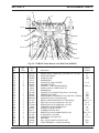
Table 1-1. PT-27 Spare Parts Kit, P/N 21623, Contents
Description Part Number Quantity
50 - 60 A Nozzle
Electrode
Swirl Baffle
Heat Shield
Standoff Guide
Valve Pin
Fuse, 15 A, 600 VDC, Fast Acting
33369
33366
33367
21616
21420
21619
952137
4
3
1
2
1
1
1

SECTION 1 DESCRIPTION
8
1.4 SPECIFICATIONS
Table 1-2. PCM-875 Specifications
*Duty cycle is based on a 10-minute period; therefore, a 60-percent duty cycle means the power source may operate for 6
minutes with a cool down period of 4 minutes and a 100-percent duty cycle means the power source may operate continuously.
Rated
Output
60% Duty Cycle* 60 A @ 120 V dc
100% Duty Cycle* 50 A @ 120 V dc
Output Current Range 10 to 60 Amperes
Open Circuit Voltage 275 V dc
Rated Primary Input
@
7.2 kW Max. Output Power
60 A @ 120 Vdc
208/230 V ac, 50/60
Hz, 3-phase
26/24 A/phase
208/230 V ac, 50/60
Hz, 1-phase
55/49 A
400 V ac, 50/60 Hz, 3-
phase
13 A/phase
460 V ac, 50/60 Hz, 3-
phase
11 A/phase
575 V ac, 50/60 Hz, 9 A/phase
Power Factor @ 60 Amperes Output
74% (208/230 V, 1-phase)
90% (208/230 V, 3-phase)
92% (400/460 & 575 V, 3-phase)
Efficiency @ 60 Amperes Output 90% Typical
Current Capacity PT-27 80 A DCSP
Air Requirements PT-27
320 cfh @ 65 - 75 psig
(150 l/min @ 4.5 - 5.2 bars)
Dimensions
Length
Height
w/handles
Width
w/o opt. storage
w/ opt. torch storage
20.3" (516 mm)
16.1" (409 mm)
18.3" (465 mm)
10.1" (275 mm)
13.1" (333 mm)
Weight of PCM-875 System
Shipping Weight
87 lbs (39.5 kg)
100 lbs (45.4 kg)

SECTION 1 DESCRIPTION
9
Table 1-3. PT-27 Torch Specifications
Current Capacity (100% duty)
Length of Service Lines
Weight
25 ft
50 ft
80 A DCSP
25 ft or 50 ft
5.2 lbs (2.4 kg)
9.6 lbs (4.4 kg)
7.3" (185 mm)
1" (25.4 mm)
1"
(25.4 mm)
75°
3" (76 mm)
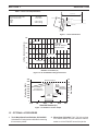
Figure 1-1. PT-27 Dimensions
Figure 1-2. PT-27/PCM 875 Cutting Performance
Figure 1-3. Standoff vs. Power Output
1.5 OPTIONAL ACCESSORIES
1. Torch Wrap/Spare Parts Kit Holder, P/N 33952GY.
Units have 4 mounting holes on left side for mounting
this accessory holder.
2. Wheel Cart, P/N 34324. This 5 7/8" high cart has
front swivel casters and rear casters to make it
easier to roll the PCM-875 around the job site.
0
1000
2000
3000
4000
5000
6000
7000
8000
9000
0.0625 0.125 0.1875 0.25 0.3125 0.375
Stand-Off Distance (in.)
Watts (A x V=W)
0
20
40
60
80
100
120
140
160
Arc Voltag
e
3/16 to 1/4“
Ma inta in P rope r
Stand-off Distance
IMPORTANT!!!
1/16 1/8
3/16
1/4
5/16
3/8
Maximum Output
Power output
increases with
stand-off distance
Best
Range
1/8 3/16 5/161/41/16
MATERIAL THICKNESS (IN.)
120
100
60
40
20
0
CUTTING SPEED (IN. PER MIN.)
80
7/16 1/2 5/89/163/8 3/4 13/16 7/811/16
PT-27 Torch
Air @75psi
3/16" - 1/4" Stand-off
Maximum Current
Steel
Aluminum
Stainless
IMPORTANT
Maintain Proper
Stand-off Distance

SECTION 2 INSTALLATION
10
2.1 GENERAL
Proper installation is important for satisfactory and trouble-
free operation of the PCM-875 cutting package. It is
suggested that each step in this section be studied
carefully and followed closely.
2.2 EQUIPMENT REQUIRED
A source of clean, dry air that supplies 320 cfh at 65-75
psig is required for the cutting operation. The air supply
should not exceed 150 psig (the maximum inlet pressure
rating of the air filter-regulator supplied with the pack-
age).
2.3 LOCATION
Adequate ventilation is necessary to provide proper
cooling of the PCM-875. The amount of dirt, dust, and
excessive heat to which the equipment is exposed,
should be minimized. There should be at least one foot
of clearance between the PCM-875 power source and
wall or any other obstruction to allow freedom of air
movement through the power source.
Installing or placing any type of filtering device will
restrict the volume of intake air, thereby subjecting
the power source internal components to overheat-
ing. The warranty is void if any type of filter device
is used.
2.4 INSPECTION
A. Remove the shipping container and all packing
material and inspect for evidence of concealed
damage which may not have been apparent upon
receipt of the PCM-875. Notify the carrier of any
defects or damage at once.
B. Check container for any loose parts prior to dispos-
ing of shipping materials.
C. Check air louvers and any other openings to ensure
that any obstruction is removed.
2.5 PRIMARY ELECTRICAL INPUT
CONNECTIONS (FIGURE 2-1)
ELECTRIC SHOCK CAN KILL! Precautionary mea-
sures should be taken to provide maximum protec-
tion against electrical shock. Be sure that all power
is off by opening the line (wall) disconnect switch
and by unplugging the power cord to the unit when
connections are made inside of the power source.
Be sure that the power source is properly configured
for your input power supply. DO NOT connect a
power source configured for 208/230 V to a 460 V
input power supply. Damage to the machine may
occur.
NOTE: If using 200(208) V input power, the PCM-875
must be reconnected for 200 V use as directed
in Section 2.7 and Fig. 2-2.
The PCM-875 consoles are equipped with a 10-ft,
4-conductor input power cable for 3-phase connection.
If single-phase connection is desired, tape back the red
wire on the input power cable.
NOTE: The 208/230 V models are equipped with a plug
for single-phase connection only. The plug is
mounted to a 4-conductor cable. If 3-phase
connection is desired, remove and discard the
plug and proceed as described above.
A line (wall) disconnect switch with fuses or circuit
breakers should be provided at the main power panel
(see Fig. 2-1 and Table 2-1 for fuse sizes). The input
power cable of the console may be connected directly to
the disconnect switch or you may purchase a proper plug
and receptacle from a local electrical supplier. If using
plug/receptacle combination, see Table 2-1 for recom-
mended input conductors for connecting receptacle to
line disconnect switch.
The chassis must be connected to an approved
electrical ground. Failure to do so may result in
electrical shock, severe burns or death.

SECTION 2 INSTALLATION
11
1. For operator safety, the torch connections are located
on the output terminal board behind the lower portion
of the front panel. Remove access door to output
terminal board from right panel of power source.
2. Thread the power cable, pilot arc cable and switch
lead of the PT-27 through the right open bushing of
the front panel. Connect power cable to the torch
fitting (left-hand threads); bolt the pilot arc cable ring
connection to the copper terminal; and plug in the
switch lead to the torch switch receptable on the
output terminal board. Make sure the power and
pilot arc cable connections are wrench-tight. Make
sure plug of switch lead is firmly locked in place.
3. Reassemble the access door to the power source.
4. Connect your air supply to the inlet connection of
the filter-regulator.
5. Clamp the work cable to the workpiece. Be sure
the workpiece is connected to an approved earth
ground with a properly sized ground cable.
Table 2-1. Recommended Sizes For
Input Conductors and Line Fuses
Input Requirements Input & Gnd Fuse
Volts Phase Amps Conductor Size
CU/AWG Amps
208 1 55A 6 80
208 3 26A/Ph. 6 50
230 1 49A 6 80
230 3 24A/Ph. 6 50
400 3 13 10 25
460 3 11 10 25
575 3 9 10 20
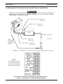
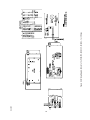
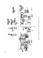
2.6 SECONDARY (OUTPUT) CONNECTIONS
(REFER TO FIG. 2-1)
Before making any connections to the power source
output terminals, make sure that all primary input
power to the power source is deenergized (off) at
the main disconnect switch and that the input power
cable is unplugged.
PRIMARY INPUT
POWER CABLE
Red - NOT USED ON SINGLE PHASE
White
Black
Green

SECTION 2 INSTALLATION
12
WORK
SAFETY
GROUND
PT-27
Allow at least 10 ft. (3m)
between work and power source
TORCH
SWITCH
RECEPTACLE
ACCESS DOOR FOR
TORCH CONNECTION
Prefiltered AIR SUPPLY
(Customer Supplied)
(90 to 150 psig max)
CUSTOMER FUSED LINE
DISCONNECT SWITCH(See
Table 2.1 and WARNING in
regards to chassis ground in
Section 2.5.)
TORCH
POWER
CABLE
CONNECTION
TORCH
PILOT
ARC
CONNECTION
INPUT POWER CABLE
(See Table 2.1)
Figure 2-1. PCM-875 Interconnection Diagram
NOTE: The 208/230 V models are equipped with a plug for
single-phase connection only. The plug is mounted to a
4-conductor cable. If 3-phase connection is desired,
remove and discard the plug and refer to Sect. 2.5.
ACCESS FOR CNC
INTERFACE CONNEC-
TIONS.
(See Detail “A”)

SECTION 2 INSTALLATION
13
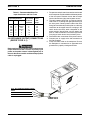
1. Remove cover from the PCM-875 power source.
2. Locate the Input Bridge (IBR) and TB5 terminal
block (see Fig. 1) on the left side towards the rear
panel. Disconnect the gray lead from TB5-2 and
then connect it to TB5-1.
3. Locate the output bridge (D1) on left side towards
the front panel (see Fig. 2). Disconnect and swap
leads X2 and X3 from the main transformer. For
200(208) vac input, X2 is connected to TB3 and X3
is connected to terminal 3 of D1. Make sure the
connections are firmly tightened.
4. Leave all other wires the same.
5. Reinstall cover and connect the PCM-875 to 208 vac
input power.
X3
TB3
X2
X1
+
FROM MAIN
TRANSFORMER
~
~
~
OUTPUT
BRIDGE (D1)
Fig. 2
2.7CONNECTING PCM-875 FOR 200(208)
VAC INPUT
ELECTRIC SHOCK CAN KILL! Precautionary mea-
sures should be taken to provide maximum protec-
tion against electrical shock. Be sure that all power
is off by opening the line (wall) disconnect switch
and by unplugging the power cord to the unit when
reconnecting for 200(208) VAC Input.
The PCM-875 power source with 200/230 vac, 1-phase
input capability is factory set for 230 vac input. If using
200(208) vac input, the PCM-875 must be reconnected
as follows before connecting to your input power:
BLK
R
R2
S
G
T
+
(IBR)
INPUT
BRIDGE
GRY
TB5
GRY
BLK
Fig. 1
Figure 2-2. Original Factory Setup for 230 Vac Input on
Power Source with 200/230 Vac Input Power Capability
1
2
3

SECTION 2 INSTALLATION
14
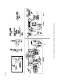
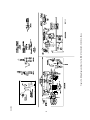
PILOT ARC CABLE - 37339 (50’)
37340 (100’)
POWER CABLE - 37341 (50’)
37342 (100’)
ARC STARTER
37338
WORK
CABLE(25’)
(Supplied with
PCM-875)
AIR HOSE - 37343 (50’)
37344 (100’)
ARC STARTER CABLE - 37410 (50’)
37411 (100’)
PT-20AM - 21785 (4.5’)
21786 (17’)
SCHEMATIC - MECHANICAL SYSTEM SETUP (See Figure 2-4 for detailed connections)
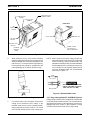
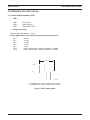
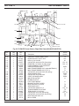
Figure 2.3 - MECHANICAL CUTTING INTERFACE DIAGRAM
CNC Interface Connection (Located inside console, left side of base.)
2.8 MECHANIZED CUTTING INSTALLATION WITH THE PT-20AM TORCH
NOTE:
Use Cable P/N 2239902
(UL / CSA approved cable
Flex, 20 guage, 12 conductor
with copper braided shield)
Installation for mechanized cutting should be performed by an experienced service technician. Do NOT permit
untrained persons to install, operate, or maintain this equipment. Be sure to read all Safety Precautions
before installing or servicing this equipment.

SECTION 2 INSTALLATION
15
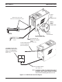
Figure 2.4 Connection Diagram - PCM-875/PT-20AM with Arc Starter
View A-A
“A”
“B”
“C”
“D”
“A”
“B”
“C”
“D”
PILOT ARC CABLE - 37339 (50’)
37340 (100’)
POWER CABLE - 37341 (50’)
37342 (100’)
AIR HOSE - 37343 (50’)
ARC STARTER CABLE - 37410 (50’)
37411 (100’)
SPLICE CONNECTOR*
(Supplied with 37338)
25mm min.
37344 (100’)
Arc Starter
37338
SPLICE CONNECTOR*
(Supplied with 37338)
25mm min.
PT-20AM
TORCH
*Insulate splice connec-
tors with vinyl tubing
and secure with electrical
tape.
SPARK GAP ASSEMBLY
(Torch end of Arc Starter)
.035” (0.9mm)
MOUNTING DIMENSIONS
7”
(178mm)
(4) .250” (6 mm)
Disconnect These
Two Black Leads
Connect Arc Start Cable As Shown. (See step 5 below).
BLK Arc Start
WHT Arc Start
Arc Starter
Cable (Ref.)
ADAPTOR - 999278
2.125”
(54mm)
Make sure all power is off before making following
connections.
1. Remove cover from PCM-875.
2. Insert the 4 service lines from Arc Starter through the
torch opening of front panel.
3. Connect large hole terminal end of Pilot Arc Cable
("A") to connection where shown. Tighten screw
firmly.
4. Connect adaptor 999278 to fitting where shown.
Connect Air Hose ("C") to adaptor. Connect power
cable ("B") to one of the threaded holes of adaptor.
Tighten all connections firmly.
5. Locate TB1 Terminal Block. Referring to view D-D
above, disconnect the two black wires from TB1.
Connect the black lead of Arc Starter Cable ("D") to
TB1-1 and the white lead to TB1-2.
6. Reassemble cover. Proceed to connect the 4 ser-
vice lines to the Arc Starter. Then connect PT-20AM
torch to Arc Starter.

SECTION 3 OPERATION
16
3.1 OPERATION
ELECTRIC SHOCK can kill.
Do NOT operate the unit with the cover removed.
Do NOT apply power to the unit while holding or
carrying the unit.
Do NOT touch any torch parts forward of the torch
handle (nozzle, heat shield, electrode, etc.) with
power switch on.
ARC RAYS can burn eyes and skin;
NOISE can damage hearing.
Wear welding helmet with No. 6 or 7 lens shade.
Wear eye, ear, and body protection.
Position the PCM-875 at least 10 feet (3 meters) from
the cutting area. Sparks and hot slag from the cut-
ting operation can damage the unit.
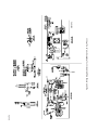
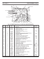
3.2 PCM-875 CONTROLS (FIGURE 3-1)
A. Power Switch (located on rear panel). When
placed in ON position, the green pilot light will glow
indicating control circuit is energized and the
cooling fan will run.
B. Output Current Control. Adjustable from 10 to
60 amperes.
C. Air Test Switch. When placed in Test position, air
filter-regulator can be adjusted to desired pres-
sure (65-75 psig) before cutting operations. Allow
air to flow for a few minutes. This should remove
any condensation that may have accumulated
during shutdown period. Be sure to place switch
in OPERATE position before starting cutting op-
erations.
D. Trigger Lock Switch. When placed in LOCK
position, this permits releasing torch switch button
after cutting arc has been initiated. To extinguish
arc at end of cut, press and release torch switch
button again or pull torch away from work. When
placed in UNLOCK position, torch switch must be
held closed by the operator during the entire
cutting operation and then released at the end of
cut.
E. Fault Light. Will glow amber under the following
conditions and operations will come to a complete
stop.
Flow Fault: The fault light will be mostly on but
will flick off for about 1/10th of a second every
second. This indicates that the air flow supply is
low.
Over Temperature: The fault light will be mostly
off but will flick on for about 1/10th of a second
every second. This indicates that the duty cycle
has been exceeded. Allow the power source to
cool down before returning to operate.
High/Low Line Voltage: The fault light will rap-
idly blink on and off (five times per second). This
indicates that the input voltage is outside the + or
- 15% range of the input rating.
Over-Current: The fault light will be on continu-
ously. This indicates that input current has been
exceeded.
All fault signals will remain on for a minimum
of 10 seconds. If fault clears, all will reset
automatically except for over-current. To clear
over-current, the power must be shut off for 5
seconds and then turned back on.
3.3 CUTTING WITH THE PT-27
Use the following procedures to cut with the PT-27 torch
(Figure 3-4).
A. Hold the torch nozzle approximately 1/8 to 3/16
inch above the work and tilted at about 15 - 30°.
This reduces the chance of spatter entering the
nozzle. If the PT-27's standoff tool is being used,
set the standoff between 3/16 and 1/4-inch.
B. Depress the torch switch. Air should flow from the
torch nozzle.
C. Two seconds after depressing the torch switch,
the pilot arc should start. The main arc should
immediately follow, allowing the cut to begin. (If
using the trigger LOCK mode, torch switch may be
released after establishing the cutting arc.)
D. After starting the cut, the torch should be main-
tained at a 5-15° forward angle (Figure 3-2). This
angle is especially useful in helping to create a
"drop" cut. When not using the standoff guide, the
nozzle should be held approximately 1/4 inch from
the work.

SECTION 3 OPERATION
17
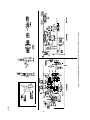
Figure 3-1. PCM-875 Controls
E. When ending a cut, the torch switch should be
released (press and release if using trigger LOCK
mode) and lifted off the workpiece just before the
end of the cut. This is to prevent the high frequency
from reigniting after cutting arc extinguishes and
causing damage to the nozzle (double arcing).
F. For rapid re-starts, such as grate or heavy mesh
cutting, do not release the torch switch. In the
postflow mode, the arc can be re-started immedi-
ately by depressing the torch switch. This avoids
the 2-second preflow portion of the cutting cycle.
REAR VIEW
AIR REGULATOR
CONTROL KNOB
FAULT LIGHT
(AMBER)
POWER LIGHT
(WHITE)
AIR
PRESSURE
GAUGE
AIR TEST
SWITCH
TRIGGER LOCK
SWITCH
CURRENT
CONTROL
KNOB
FUSE (15A)
POWER ON-OFF
(I-O) SWITCH &
CIRCUIT BREAKER
FUSE (3A)
Figure 3-2. Recommended Torch Angle of 5° to 15°
NOTE: When replacing the nozzle, always inspect the
electrode for wear. If less than 19/32" of electrode
shaft is remaining, replace the electrode. If the
electrode is used beyond this recommended wear
limit, damage to the torch and power source may
occur. Nozzle life is also greatly reduced when
using the electrode below the recommended
limit. Refer to Figure 3-3.
Figure 3-3. Electrode Wear Limit
19/32"
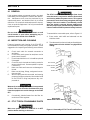
3.3.1. Drag Cutting with the PT-27/PCM-875 System
If drag cutting is desired, the 15 amp pilot arc fuse located
on the rear panel must be removed. This converts pilot arc
starting to high frequency starting allowing you to cut by
dragging the torch nozzle on the workpiece. Cutting
thickness should not exceed 3/8" for drag cutting.
(15.1 mm)
ELECTRODE
REPLACE ELECTRODE BEFORE
LENGTH BECOMES SHORTER
THAN 19/32 INCH (15.1 MM)

SECTION 3 OPERATION
18
WHEN THE ARC BREAKS
THROUGH THE WORK,
BRING THE TORCH TO AN
UPRIGHT POSITION AND
PROCEED TO CUT.
TO START A PIERCE, TILT THE
TORCH TO PREVENT MOLTEN MA-
TERIAL FROM COMING BACK
AGAINST AND DAMAGING THE
TORCH.
1
2
Figure 3-4. Piercing Technique using the PT-27
3.4 COMMON CUTTING PROBLEMS
Listed below are common cutting problems followed by
the probable cause of each. If problems are determined
to be caused by the PCM-875, refer to the maintenance
section of this manual. If the problem is not corrected
after referring to the maintenance section, contact your
ESAB distributor.
A. Insufficient Penetration.
1. Current too low.
2. Cutting speed too fast.
3. Damaged cutting nozzle.
4. Improper air pressure.
5. Low air flow rate.
B. Main Arc Extinguishes.
1. Cutting speed too slow.
2. Worn electrode.
C. Dross Formation. (In some materials and thick-
nesses, it may be impossible to get dross-free cuts.)
1. Current too low.
2. Cutting speed too fast or too slow.
3. Improper air pressure.
4. Faulty nozzle or electrode.
5. Low air flow rate.
D. Double Arcing. (Damaged Nozzle Orifice.)
1. Low air pressure.
2. Damaged cutting nozzle.
3. Loose cutting nozzle.
4. Heavy spatter accumulation on nozzle.
E. Uneven Arc.
1. Damaged cutting nozzle or worn electrode.
F. Unstable Cutting Conditions.
1. Incorrect cutting speed.
2. Loose cable or hose connections.
3. Electrode and/or cutting nozzle in poor condi-
tion.
G. Main Arc Does Not Strike.
1. Worn electrode.
2. Loose connections.
3. Worn cable not attached.
H. Poor Consumable Life.
1. Improper gas pressure.
2. Contaminated air supply.
3. Low air flow rate.

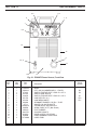
SECTION 4 MAINTENANCE
19
4.1 GENERAL
If this equipment does not operate properly, stop work
immediately and investigate the cause of the malfunc-
tion. Maintenance work must be performed by an
experienced person, and electrical work by a trained
electrician. Do not permit untrained persons to inspect,
clean, or repair this equipment. Use only recommended
replacement parts.
Be sure that the wall disconnect switch or wall
circuit breaker is open before attempting any in-
spection or work inside of the PCM-875.
4.2 INSPECTION AND CLEANING
Frequent inspection and cleaning of the PCM-875 is
recommended for safety and proper operation. Some
suggestions for inspecting and cleaning are as follows:
A. Check work cable for secured connection to
workpiece.
B. Check safety earth ground at workpiece and at
power source chassis.
C. Check heat shield on torch. It should be replaced
if damaged.
D. Check the torch electrode and cutting nozzle for
wear on a daily basis. Remove spatter or replace
if necessary.
E. Make sure cable and hoses are not damaged or
kinked.
F. Make sure all plugs, fittings, and ground connec-
tions are tight.
G. With all input power disconnected, and wearing
proper eye and face protection, blow out the inside
of the PCM-875 using low-pressure dry com-
pressed air.
Water or oil occasionally accumulates in compressed
air lines. Be sure to direct the first blast of air away
from the equipment to avoid damage to the PCM-
875.
H. Occasionally, bleed all water from the filter be-
neath the air filter-regulator.
4.3 PT-27 TORCH CONSUMABLE PARTS
Make sure power switch on PCM-875 is in OFF
position before working on the torch.
The PT-27 torch head contains a gas flow check
valve that acts in conjunction with the flow switch
and circuitry within the power source. This system
prevents the torch from being energized with high
voltage if the torch switch is accidentally closed
when the shield is removed. Always replace torch
with the proper torch manufactured by ESAB since
it alone contains ESAB¹s patented safety interlock.
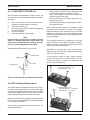
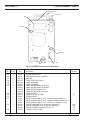
To assemble the consumable parts, refer to Figure 4-1.
A. Place nozzle, swirl baffle and electrode into the
shield as shown.
B. Thread assembly to the torch body and hand tighten.
Always make sure the shield is very tight before
cutting.
Figure 4-1. Assembly of PT-27 Torch Front End Parts
SWIRL BAFFLE
ELECTRODE
NOZZLE
SHIELD
IMPORTANT!
MAKE SHIELD VERY TIGHT!
La page est en cours de chargement...
La page est en cours de chargement...
La page est en cours de chargement...
La page est en cours de chargement...
La page est en cours de chargement...
La page est en cours de chargement...
La page est en cours de chargement...
La page est en cours de chargement...
La page est en cours de chargement...
La page est en cours de chargement...
La page est en cours de chargement...
La page est en cours de chargement...
La page est en cours de chargement...
La page est en cours de chargement...
La page est en cours de chargement...
La page est en cours de chargement...
La page est en cours de chargement...
La page est en cours de chargement...
La page est en cours de chargement...
La page est en cours de chargement...
La page est en cours de chargement...
La page est en cours de chargement...
La page est en cours de chargement...
La page est en cours de chargement...
La page est en cours de chargement...
La page est en cours de chargement...
La page est en cours de chargement...
La page est en cours de chargement...
-
 1
1
-
 2
2
-
 3
3
-
 4
4
-
 5
5
-
 6
6
-
 7
7
-
 8
8
-
 9
9
-
 10
10
-
 11
11
-
 12
12
-
 13
13
-
 14
14
-
 15
15
-
 16
16
-
 17
17
-
 18
18
-
 19
19
-
 20
20
-
 21
21
-
 22
22
-
 23
23
-
 24
24
-
 25
25
-
 26
26
-
 27
27
-
 28
28
-
 29
29
-
 30
30
-
 31
31
-
 32
32
-
 33
33
-
 34
34
-
 35
35
-
 36
36
-
 37
37
-
 38
38
-
 39
39
-
 40
40
-
 41
41
-
 42
42
-
 43
43
-
 44
44
-
 45
45
-
 46
46
-
 47
47
-
 48
48


ESAB PCM-875 Manuel utilisateur
- Catégorie
- Système de soudage
- Taper
- Manuel utilisateur
dans d''autres langues
- English: ESAB PCM-875 User manual
Documents connexes
-
ESAB 652cv & 782cv Power Sources Manuel utilisateur
-
-
-
-
-
