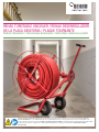
Rehau Turntable Uncoiler Product Instructions
- Catégorie
- Outils électroportatifs
- Taper
- Product Instructions

Read this instruction manual thoroughly before use and follow all safety precautions - improper use can cause personal injury. SAVE THIS
INSTRUCTION MANUAL. Lea este manual de instrucciones completamente antes de usar y siga todas las precauciones de seguridad; el uso
incorrecto puede provocar lesiones físicas. GUARDE ESTE MANUAL DE INSTRUCCIONES. Lire attentivement le manuel d’instruction avant d’utiliser
l’outil et respecter toutes les consignes de sécurité; l’utilisation inadéquate de l’outil peut causer blessures. CONSERVER CE MANUEL
D’INSTRUCTION.
REHAU TURNTABLE UNCOILER / REHAU DESENROLLADOR
DE LA PLACA GIRATORIA / PLAQUE TOURNANTE
Product Instructions / Instrucciones del producto / Instructions relatives au produit

1. Scope 2
2. Safety Warnings 3
3. Main Parts / Specications 4
4. Assembling the Uncoiler 5
5. Using the Uncoiler 12
6. Inspection, Maintenance, Cleaning,
Transportation and Storage 14
7. Additional Information 15
CONTENTS
For updates to this publication and the most current technical instructions, safety information and manufacturer’s recommendations, visit www.na.rehau.com/resourcecenter
1. SCOPE
Thank you for your purchase. This product instruction manual
contains information about the proper use of the REHAU Turntable
Uncoiler (uncoiler). To receive maximum performance and satisfaction
from your uncoiler, and to reduce risk of injury or property damage
from its use, it is important that you read, understand and follow the
instructions and warnings found in this manual.
For professional use only. Persons assembling and using the uncoiler
must be experienced and appropriately licensed professional
contractors who understand the principles and practices associated
with the proper use of tools and the proper installation of hot- and
cold-water potable and hydronic systems.
The Turntable Uncoiler is designed for use with REHAU PEXa
pipe in sizes 3/8 in. to 1 in.
The information presented in this product instruction manual is
intended to demonstrate the proper use and function of the uncoiler.
Allow only persons who fully understand this manual to operate the
uncoiler. Do not lend or rent the tool without this instruction manual.
Nothing in this manual supersedes national or local code require-
ments. Observe all applicable national, state and local laws, regula-
tions, standards, codes and ordinances when installing REHAU PEXa
pipe. If you believe REHAU product information conicts with
applicable code requirements or industry standards, contact the
REHAU distributor in your area and consult with the authority having
jurisdiction before installing REHAU PEXa pipe.
Proper usage is the responsibility of the installing contractor. Review
the REHAU PEXa Limited Warranty, available at www.na.rehau.com/
warranties. It can also be obtained from your authorized REHAU
distributor or by writing to REHAU Construction LLC, 1501 Edwards
Ferry Road NE, Leesburg VA 20176 US. Review REHAU Technical
Guidelines prior to installation of the REHAU crosslinked polyethylene
(PEXa) piping system. REHAU Technical Guidelines are dened in the
REHAU PEXa Limited Warranty as: The most current and applicable
versions of all the technical literature available on the REHAU North
America website at www.na.rehau.com/resourcecenter, including, but
not limited to, technical manuals, instruction guides, technical
bulletins, submittals and REHAU Academy training presentations.
Contact the REHAU distributor in your area if you do not understand
the information in this manual or if you have questions about the
REHAU Technical Guidelines.
2

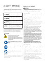
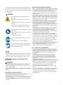
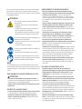
This manual contains safety-related information that requires your
special attention. It is indicated with the safety alert symbol and the
signal words described below:
DANGER
Indicates a hazardous situation which, if not
avoided, will result in death or serious injury.
WARNING
Indicates a hazardous situation which, if not
avoided, could result in death or serious
injury.
CAUTION
Indicates a hazardous situation which, if not
avoided, could result in minor or moderate
injury.
NOTICE
Indicates a risk of property damage,
including damage to tool or its individual
components.
Only trained personnel should operate this tool. Follow the instructions
in this manual and other REHAU Technical Guidelines and use
common sense to reduce the risk of injury or property damage.
CAUTION
To avoid pinching when operating uncoiler:
- Do not drop pipe coils when loading.
- Use caution when inserting or removing release pins.
- Use caution when cutting nylon strings, pipe coil will
suddenly expand.
To avoid pinching when assembling or repositioning
uncoiler:
- Keep hands and feet away from base of uncoiler.
- Wear safety shoes.
Assembled uncoiler weight is over 50 lbs (23 kg):
- Two-person lift required.
To reduce the risk of injury, read this instruction
manual along with all cautions before assembly or
operation.
NOTICE
This uncoiler is designed for dispensing REHAU PEXa pipes. Use only
for intended purpose. Maximum pipe weight on uncoiler shall not
exceed 110 lbs (50kg).
2. SAFETY WARNINGS GENERAL TOOL SAFETY WARNINGS
CAUTION
- Read all safety warnings and all instructions. Failure to follow
the warnings and instructions may result in personal injury or
property damage.
- Save all warnings and instructions for future reference.
WORK AREA SAFETY
- Keep work area clean and well lit. Cluttered or dark areas invite
accidents.
- Keep children and bystanders away while assembling and
operating the tool. Distractions can cause you to lose control.
PERSONAL SAFETY WARNINGS
- Use personal protective equipment. Always wear safety shoes
when assembling and operating uncoiler. Protective equipment
such as dust mask, hard hat, eye protection or hearing protection
used for appropriate job site conditions will reduce the risk of
personal injuries.
- Dress properly. Do not wear loose clothing or jewelry. Keep
hair, clothing and gloves away from moving parts. Loose
clothes, jewelry or long hair can be caught in moving parts.
- Do not operate the tool while under the inuence of any
substance (drug, alcohol, medication, etc.) that might impair
vision, balance, dexterity or judgement. A moment of inattention
may result in personal injury.
- Do not let familiarity gained from frequent use of tools allow
you to become complacent and ignore tool safety principles.
A careless action can cause injury within a fraction of a second.
- Working with this tool can be strenuous. The operator must be
in good physical condition. To reduce the risk of injury from loss of
control, be alert. Do not operate the tool when tired. Take a break if
you become tired. Always hold the tool rmly while working as
directed in the instruction manual.
- Do not overreach. Keep proper footing and balance at all
times. Use caution when working from a ladder or other elevated
platform.
TOOL USE AND CARE
- Always inspect the uncoiler for damage or excess wear prior
to each use. Do not use uncoiler if it has been damaged. If the
uncoiler has been damaged it must be replaced.
- The uncoiler is designed for two-handed operation. Keep a
secure grasp on the handlebar when repositioning the
uncoiler. Loss of control can lead to personal injury or property
damage.
- Tire pressure should be maintained at 28 psi. Maximum ination
pressure of 30 psi. Never over-inate tires. Never use air compres-
sor to ll tires. Inate with manual pump only.
- Do not ride on uncoiler. Use only for intended purposes.
- Only use uncoiler on at/stable ground. Uneven or unstable
surfaces may cause uncoiler to tip over, resulting in personal injury
or property damage.
3

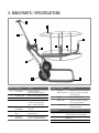
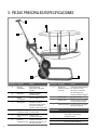
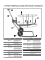
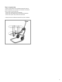
3. MAIN PARTS / SPECIFICATIONS
Feature Description Function
A Uncoiler Base Resting foundation of
uncoiler when dispensing pipe
B Pneumatic Tires Allows for easy mobility of uncoiler
C Reel/Turntable Rotates to dispense pipe
D Rotating Arm Reorients Reel from horizontal
to vertical to fit through tight
spaces or framed doorways
E Handlebar with
Comfort Grips
Provides comfortable control
of uncoiler
F Pipe Dispensing
Guide
Dispenses pipe in the
intended direction
G Configurable
Rod Positions
Provides tight fitment between
various I.D. of REHAU PEXa pipe
Feature Description Function
H Reel Arm
Alignment Notches
Indicates when holes in Reel Arm
and Uncoiler Frame are aligned
to insert Hitch Pin
I Spindle Axle for rotation of Reel
J NOTICE Label Provides information indicating
risk of property damage
K CAUTION Label Provides information indicating
hazardous situations
Specifications
Weight 88.5 lbs (40.1 kgs)
Fully assembled uncoiler without pipe
Paint Type
Powdercoat
Paint Color
Sherwin Williams Regal Red
AB
C
D
E
F
G
H
I
J
K
4

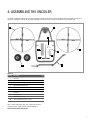
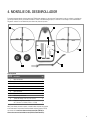
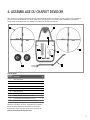
4. ASSEMBLING THE UNCOILER
Parts List
Item No. Description Qty
1 Reel Arm 1
2 Pipe Guide 1
3 Uncoiler Frame 1
4 Wheel with Pneumatic Tire 2
5 Handlebar with Hand grips 1
6 Reel Base 1
7 Reel Cap 1
8 Reel Hub Bar 4
9 Handle Nut (1/2"-13) 4
10 Tethered Hitch Pin (5/16" x 1 5/8") 1
Note: To obtain replacement parts, refer to spare parts list in the
Turntable Uncoiler Product Submittal, PS578, available at:
www.na.rehau.com/resourcecenter
The REHAU Turntable Uncoiler requires two-person assembly. Carefully unpack box and ensure all required parts and hardware are included. If
any parts are damaged or missing, do not continue assembly or use of the uncoiler. Contact your distributor for replacement parts.
2
1
3
4
6
5
78
9
10
5

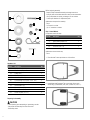
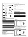
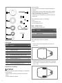
Hardware List
Item No. Description Qty
11 Hex Jam Nut (1/2"-13) 1
12 Flat Washer (1") 1
13 R-Clip (1/8") 1
14 Flat Washer (5/8") 2
15 Cotter Pin (1/8" x 1") 2
16 Hex Head Cap Screw (5/16"-18 x 1 3/4") 1
17 Elastic Stop Nut (5/16"-18) 1
18 Plastic Washer (1") 1
19 Plastic Washer (1/2") 1
20 Fender Washer (1/2") 2
21 Elastic Stop Nut (1/2"-13) 1
Preparing for Assembly
CAUTION
To avoid pinching when assembling or repositioning uncoiler:
- Keep hands and feet away from base of uncoiler.
- Wear safety shoes.
Before beginning assembly:
- Read and fully understand assembly and usage instructions
- Verify all parts and hardware with list in these product instructions.
If any components are missing or damaged, do not continue.
- Contact your distributor for replacement parts.
Additional tools required for assembly:
- Pliers
- 3/4” wrench or socket
- (2) 1/2” wrenches or sockets
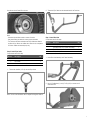
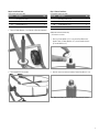
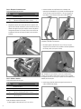
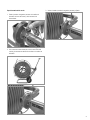
Step 1: Install Wheels
Components used in this step:
Item No. Description Qty
3 Uncoiler Frame 1
4 Wheel with Pneumatic Tire 2
14 Flat Washer (5/8") 2
15 Cotter Pin (1/8" x 1") 2
Additional tools used in this step:
- Pliers
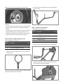
1. Place Uncoiler Frame upside down on a at surface.
2. Install Wheel with Pneumatic Tire on each axle. Secure each
wheel using (1) Flat Washer (5/8") and (1) Cotter Pin (1/8" x 1").
12
19
20
14
18
16
21
13
15
17
11
6

Use pliers to bend Cotter Pin as shown.
Note:
- Valve stem should face inward to center of uncoiler.
- Use grease tting as needed to ensure proper lubrication.
- Tire pressure should be maintained at 28 psi. Maximum ination
pressure 30 psi. Never over-inate tires. Never use air compressor
to ll tires. Inate with manual pump only.
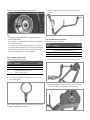
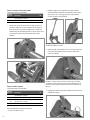
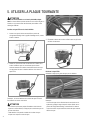
Step 2: Install Pipe Guide
Components used in this step:
Item No. Description Qty
1 Reel Arm 1
2 Pipe Guide 1
11 Hex Jam Nut (1/2"-13) 1
1. Thread Hex Jam Nut (1/2"-13) onto the Pipe Guide.
Note: The Hex Jam Nut allows users to adjust feed angle as desired.
2. Thread the Pipe Guide into the threaded end of the Reel Arm.
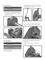
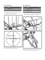
Step 3: Install Reel Arm
Components used in this step:
Item No. Description Qty
Assembly from Step 1 (Reel Arm Assembly)
1
Assembly from Step 2 (Frame Assembly) 1
12 Flat Washer (1") 1
13 R-Clip (1/8") 1
1. Insert Reel Arm Assembly into Frame Assembly.
2. Use (1) Flat Washer (1") and (1) R-Clip (1/8") to secure end of
shaft as shown.
7

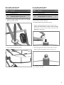
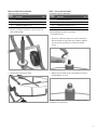
Step 4: Lock Reel Arm
Components used in this step:
Item No. Description Qty
Assembly from Step 3 1
10 Tethered Hitch Pin (5/16" x 1 5/8") 1
1. Make sure Reel Arm is in the lowest position. Use alignment
notches to align holes for Tethered Hitch Pin. Install one end of
Tethered Hitch Pin (5/16”) into mating holes in the Reel Arm
Assembly and Frame Assembly.
Step 5: Install Handlebar
Components used in this step:
Item No. Description Qty
Assembly from Step 4 1
5 Handlebar with Hand Grips 1
16 Hex Head Cap Screw (5/16"-18 x 1 3/4") 1
17 Elastic Stop Nut (5/16"-18) 1
Additional tools used in this step:
- (2) 1/2" wrenches or sockets
1. Install Handlebar with Hand Grips onto Uncoiler Frame Assembly
using (1) Hex Head Cap Screw (5/16"-18 x 1 3/4") and (1) Elastic
Stop Nut (5/16”-18) in the LOWER hole.
Note: NOTICE safety label should be on same side as CAUTION label
on frame.
2. Use 1/2" wrenches or sockets to ensure the Elastic Stop Nut is
engaged in the threads to prevent the bolt from working loose.
Note: Ensure nut and bolt in lower hole allow Handlebar to hinge when
Tethered Hitch Pin is removed so that Handlebar can be rotated
forward for transport.
3. Install the other half of Tethered Hitch Pin into UPPER hole in
Handlebar.
8

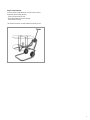
Step 6: Install Reel Base
Components used in this step:
Item No. Description Qty
Assembly from Step 5 1
6 Reel Base 1
18 Plastic Washer (1") 1
1. Place (1) Plastic Washer (1”) on Spindle on Reel Arm Assembly.
2. Place Reel Base on the Spindle.
Step 7: Secure Reel Base
Components used in this step:
Item No. Description Qty
Assembly from Step 6 1
19 Plastic Washer (1/2") 1
20 Fender Washer (1/2") 2
21 Elastic Stop Nut (1/2"-13) 1
Additional tools used in this step:
- 3/4" wrench or socket
1. Place (1) Fender Washer (1/2”) on top of the Reel Base on the
Spindle. Place (1) Plastic Washer (1/2”) on the Spindle and then
(1) Fender Washer (1/2”).
2. Use 3/4” wrench or socket to install (1) Elastic Stop Nut (1/2”-13).
Note: Make sure Elastic Stop Nut is tight and then back-off 1/4 turn.
9

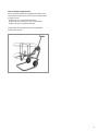
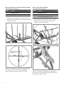
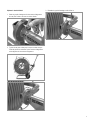
Step 8: Install Reel Hub Bars
Components used in this step:
Item No. Description Qty
Assembly from Step 7 1
8 Reel Hub Bar 4
1. Install (4) Reel Hub Bars into desired set of holes to create the
proper diameter to accept the PEXa pipe coil.
Note: Threaded holes in Reel Base are placed 14", 16" and 18" apart
to closely t the I.D. of different REHAU PEXa pipe coils.
Step 9: Secure Reel Cap
Components used in this step:
Item No. Description Qty
Assembly from Step 8 1
7 Reel Cap 1
9 Handle Nut (1/2"-13) 4
1. Align Reel Cap onto the (4) Reel Hub Bars matching the hub bar
locations. Secure with (4) Handle Nuts (1/2”-13) as shown.
Note: When properly installed, holes in Reel Cap will be on the same
side of spokes as threaded plate on Reel Base (shown above).
10

Step 10: Final Inspection
Once the uncoiler is fully assembled, do a nal check for proper
functionality before loading with pipe:
- Ensure no components are loose
- Ensure Reel rotates and functions properly
- Ensure wheels roll freely
The Turntable Uncoiler is now fully assembled and ready for use.
11

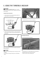
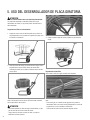
5. USING THE TURNTABLE UNCOILER
CAUTION
Only use uncoiler on at/stable ground. Uneven or unstable
surfaces may cause uncoiler to tip over, resulting in personal injury or
property damage.
Loading PEXa Pipe onto Uncoiler
1. Ensure Reel is locked in the loading/dispensing position with
Tethered Hitch Pin, as shown below.
2. Remove (4) Handle Nuts and Reel Cap. Load pipe, ensuring the
Reel Hub Bars are located to closely t the inside diameter of the
PEXa pipe coil.
Note: The inside edge of the PEXa pipe coil should be towards the
bottom of the spool.
CAUTION
- To avoid pinching while loading uncoiler, do not drop pipe coils on
Reel Base.
- Use caution when cutting nylon strings, pipe coil will suddenly
expand
3. Reinstall Reel Cap and secure with (4) Handle Nuts.
Dispensing the PEXa Pipe
Route pipe through Pipe Guide to dispense.
Note:
- Coil should feed out in a clockwise direction when the uncoiler is in
loading/dispensing position, through the Pipe Guide.
- Cut nylon ties from coil before dispensing pipe.
12

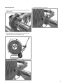
Repositioning the Reel
1. Remove Tethered Hitch Pin from Reel Arm and Uncoiler Frame
alignment rings.
2. Rotate the Reel Arm until the PEXa pipe coil is vertical and the
alignment notches match in the alignment rings.
3. Reinstall Tethered Hitch Pin and secure.
13

6. INSPECTION, MAINTENANCE, CLEANING,
TRANSPORTATION AND STORAGE
Regular Inspection
- Before assembling or operating, inspect all parts for visible wear and
damage.
- Never operate the uncoiler if it is damaged, not completely assembled, or
not functioning properly. If damaged, it must be replaced.
- Using a damaged uncoiler may result in the tool to malfunction, which can
lead to personal injury .
Maintenance
- Use grease ttings as needed to ensure proper lubrication.
- Maintain proper tire pressure. Tire pressure should be maintained at 28
psi. Maximum ination pressure is 30 psi. Never over-inate tires. Never
use air compressor to ll tires. Inate with manual pump only.
- Replace on-product labels that are worn, damaged, or missing. Contact
your local REHAU representative for replacement labels.
- If paint chips, use touch-up paint to repair to avoid rust forming.
Cleaning
- When soiled, clean with a solution of water and mild soap, let air dry
before storage.
Transportation
- Always remove PEXa pipe coil before preparing for transportation.
- For transport, fold Handlebar towards turntable by removing Hitch Pin.
- Assembled uncoiler weight exceeds 50 lbs (23 kg). A two-person lift is
required to avoid injury.
- Secure uncoiler inside vehicle when transporting to avoid personal injury
and property damage.
Storage
- When not in use, store in clean, dry place. Do not store in damp environ-
ment or in direct sunlight.
- Do not store uncoiler when loaded with PEXa pipe coil
- Never store uncoiler when wet, allow to dry properly before storing.
14

7. ADDITIONAL INFORMATION
For Professional Use Only
Proper preparation and installation is the responsibility of the installing
contractor. Only trained personnel should operate this tool. Persons
using the uncoiler must be experienced and appropriately licensed
professional contractors who understand the principles and practices
associated with the proper installation of hot- and cold-water potable
and hydronic systems.
Engineering Changes
Because REHAU believes in the continual improvement of its products,
engineering changes are made from time to time. Therefore, some
changes or improvements may not be covered in this manual. If you
have questions about operating characteristics or features that are
different from those described in this manual, please contact the
REHAU distributor in your area for assistance.
Technical Guidelines
For a full list of REHAU Technical Guidelines, please visit
www.na.rehau.com/resourcecenter
Spare Parts
Contact your local REHAU distributor for spare parts.
Limited Warranty
This product is sold subject to the REHAU PEXa Limited Warranty,
available at www.na.rehau.com/warranties. It can also be obtained
from your authorized REHAU distributor or by writing to REHAU
Construction LLC, 1501 Edwards Ferry Road NE, Leesburg VA 20176
US.
Refer to the REHAU PEXa Limited Warranty for more information.
When sending parts for service, include original purchase
documentation.
Customer Support
For customer support, contact your nearest REHAU Construction Sales
Ofce, available at www.na.rehau.com/contact.
15

1. Alcance 16
2. Advertencias de seguridad 16
3. Piezas principales/Especicaciones 18
4. Montaje del desenrollador 19
5. Uso del desenrollador 26
6. Inspección, mantenimiento, limpieza,
transporte y almacenamiento 28
7. Información adicional 29
ÍNDICE
Para acceder a las actualizaciones de esta publicación y a las instrucciones técnicas, información de seguridad y recomendaciones del fabricante más actuales,
visite www.na.rehau.com/resourcecenter (US/CA) or www.rehau.com.mx/centralderecursos (México/Centroamérica).
1. ALCANCE
Gracias por su compra. Este manual de instrucciones del producto
contiene información acerca del uso correcto del REHAU desenrolla-
dor de placa giratoria (desenrollador). Para obtener el desempeño
máximo y la mayor satisfacción con su desenrollador, y además
reducir el riesgo de lesiones o daños materiales con su uso, es
importante que usted lea, entienda y siga las instrucciones y
advertencias que contiene este manual.
Para uso profesional solamente. Las personas que monten y usen el
desenrollador deben ser contratistas profesionales debidamente
autorizados y experimentados que entiendan los principios y las
prácticas asociados con el uso correcto de las herramientas y la
instalación adecuada de sistemas hidrónicos de agua potable fría y
caliente.
El desenrollador de placa giratoria está diseñado para usarlo
con los tubos PEXa de REHAU de 9,52 mm (3/8 in) a 25,4 mm
(1 in).
La información que se presenta en este manual de instrucciones del
producto pretende demostrar el uso y funcionamiento adecuados del
desenrollador. Permita que solo las personas que entiendan comple-
tamente este manual operen el desenrollador. No preste ni alquile la
herramienta sin este manual de instrucciones.
Nada de lo contenido en este manual reemplaza los requisitos de los
códigos locales o nacionales. Cumpla con todas las leyes, regulacio-
nes, normas, códigos y ordenanzas locales, estatales y nacionales
aplicables cuando instale los tubos PEXa de REHAU. Si usted cree
que la información del producto de REHAU entra en conicto con los
requisitos de los códigos aplicables o los estándares de la industria,
comuníquese con el distribuidor de REHAU en su área y consulte con
la autoridad con jurisdicción competente antes de instalar los tubos
PEXa de REHAU.
El uso correcto es responsabilidad del contratista instalador. Revise la
Garantía limitada PEXa de REHAU, que encontrará en www.na.rehau.
com/warranties. También puede obtenerla a través de su distribuidor
REHAU autorizado o solicitarla por escrito a REHAU Construction LLC,
1501 Edwards Ferry Road NE, Leesburg VA 20176 US. Consulte las
Directrices técnicas de REHAU antes de la instalación del sistema de
tuberías de polietileno reticulado (PEXa) de REHAU. Las Directrices
técnicas de REHAU están denidas en la Garantía limitada PEXa de
REHAU, a saber: Las versiones más actuales y vigentes de toda la
documentación técnica están disponibles en el sitio web de REHAU
Norteamérica en www.na.rehau.com/resourcecenter, incluidos entre
otros, manuales técnicos, manuales de instrucciones, boletines
técnicos, presentaciones y presentaciones de disertaciones de la
Academia REHAU.
Comuníquese con el distribuidor de REHAU de su área si no entiende
la información contenida en este manual o si tiene alguna pregunta
acerca de las Directrices técnicas de REHAU.
Este manual contiene información de seguridad que requiere su
especial atención. Está indicada con el símbolo de alerta de seguridad
y el texto de señalización que se describe a continuación:
2. ADVERTENCIAS DE
SEGURIDAD
PELIGRO
Indica una situación peligrosa que, si
no se evita, provocará la muerte o
lesiones graves.
ADVERTENCIA
Indica una situación peligrosa que, si
no se evita, provocaría la muerte o
lesiones graves.
ATENCIÓN
Indica una situación peligrosa que, si
no se evita, provocaría lesiones
menores o moderadas.
AVISO
Indica el riesgo de daños materiales,
incluso daños a la herramienta o a sus
componentes individuales.
16

Solo el personal capacitado puede operar esta herramienta. Siga las
instrucciones contenidas en este manual y demás Directrices técnicas
de REHAU y use el sentido común para reducir el riesgo de lesiones o
de daños materiales.
ATENCIÓN
Para evitar apretarse los dedos mientras opera el
desenrollador:
- No deje caer los rollos de tubo al momento de la
carga.
- Tenga atención al insertar o retirar los pasadores de
liberación.
- Tenga atención al cortar cordones de nailon, los
rollos de tubo se expandirán de forma repentina.
Para evitar apretarse los dedos al montar o reubicar el
desenrollador:
- Mantenga las manos y los pies lejos de la base del
desenrollador.
- Use zapatos de seguridad.
El peso del desenrollador montado es más de 23 kg
(50 lb):
- Se necesitan dos personas para levantarlo.
Para reducir el riesgo de lesión, lea este manual de
instrucciones, junto con todas las precauciones antes
del montaje y funcionamiento.
AVISO
Este desenrollador está diseñado para dispensar los tubos PEXa de
REHAU. Solo use el producto para el n previsto. El peso máximo de
los tubos en el desenrollador no debe exceder los 50 kg (110 lb).
ADVERTENCIAS GENERALES DE SEGURIDAD DE LA
HERRAMIENTA
ATENCIÓN
- Lea todas las instrucciones y advertencias de seguridad. No
cumplir las advertencias e instrucciones puede provocar lesiones
físicas o daños materiales.
- Guarde todas las instrucciones y advertencias para referencia
futura.
SEGURIDAD EN EL ÁREA DE TRABAJO
- Mantenga el área de trabajo limpia y bien iluminada. Las áreas
oscuras o desordenadas favorecen los accidentes.
- Mantenga alejados a los niños y transeúntes cuando ensamble
y opere la herramienta. Las distracciones pueden hacerlo perder
el control.
ADVERTENCIAS DE SEGURIDAD PERSONAL
- Utilice el equipo de protección personal. Siempre use zapatos
de seguridad cuando monte y opere el desenrollador. El equipo
de protección, como máscaras antipolvo, cascos o protectores
oculares y auditivos, utilizado en las condiciones adecuadas reducirá
las lesiones físicas.
- Use vestimenta adecuada. No use prendas sueltas ni alhajas.
Mantenga el cabello, la ropa y los guantes lejos de las piezas
móviles. Las prendas sueltas, las alhajas o el cabello largo pueden
quedar atrapados en las piezas móviles.
- No opere la herramienta si está bajo la inuencia de alguna
sustancia (drogas, alcohol, medicación, etc.) que pueda
provocar alteración de la visión, el equilibrio, la destreza o el
razonamiento. Un momento de falta de atención puede provocar
lesiones físicas.
- No permita que la familiaridad obtenida por el uso frecuente
de las herramientas lo vuelva complaciente e ignore los
principios de seguridad de la herramienta. Un descuido puede
provocar lesiones en una fracción de segundo.
- Trabajar con esta herramienta puede ser una tarea ardua. El
operador debe estar en buenas condiciones físicas. Para reducir el
riesgo de lesiones por pérdida de control, preste atención. No opere
la herramienta si está cansado. Si siente cansancio, tome un
descanso. Siempre sostenga la herramienta con rmeza mientras
trabaja tal como se indica en el manual de instrucciones.
- No se estire demasiado. Mantenga el punto de apoyo adecua-
do y el equilibrio en todo momento. Tenga cuidado cuando
trabaja desde una escalera u otra plataforma elevada.
USO Y CUIDADO DE LA HERRAMIENTA
- Siempre inspeccione el desenrollador para detectar daños o
desgaste excesivo antes de cada uso. No utilice el desenrolla-
dor si está dañado. Si el desenrollador presenta daños, debe
reemplazarlo.
- El desenrollador está diseñado para operar con las dos
manos. Sujete rmemente el manillar cuando reubique el
desenrollador. La pérdida de control puede provocar lesiones
físicas o daños materiales.
- La presión de los neumáticos debe mantenerse a 1,93 bar (28
lb/in
2
). Presión máxima de inado de 2,07 bar (30 lb/in
2
). Nunca
ine los neumáticos en exceso. Nunca use un compresor de aire
para inar los neumáticos. Ine solo con bomba manual.
- No se monte sobre el desenrollador. Úselo solo para los nes
previstos.
- Solo use el desenrollador sobre una supercie plana/estable.
Las supercies desparejas o inestables pueden hacer que el
desenrollador se vuelque, lo que puede producir lesiones físicas o
daños materiales.
17

3. PIEZAS PRINCIPALES/ESPECIFICACIONES
Característica
Descripción Función
A Base del
desenrollador
Base de apoyo del
desenrollador al dispensar
los tubos
B Neumáticos Facilita la movilidad
del desenrollador
C Carrete/
Placa giratoria
Gira para dispensar el tubo
D Brazo giratorio Reorienta el carrete de
posición horizontal a vertical
para caber por espacios
reducidos o pasar por las puertas
E Manillar con
empuñadura cómoda
Brinda un control cómodo
del desenrollador
F Guía para dispensar
el tubo
Dispensa el tubo
en la dirección prevista
G Posiciones
ajustables de la varilla
Proporciona un ajuste
adecuado entre varios D.I. del
tubo PEXa de REHAU
Característica
Descripción Función
H Muescas de
alineación del brazo
del carrete
Indica cuando están alineados
los orificios en el brazo
del carrete y la estructura
del desenrollador para
insertar el pasador de enganche
I Eje del husillo para girar el carrete
J Etiqueta AVISO Brinda información que indica
un riesgo de daño material
K
Etiqueta PRECAUCIÓN
Brinda información que indica
situaciones peligrosas
Especificaciones
Peso 40,1kg (88,5lb)
Desenrollador completamente
montado sin el tubo
Tipo de pintura
Revestimiento de polvo
Color de la pintura
Rojo real de Sherwin Williams
AB
C
D
E
F
G
H
I
J
K
18

4. MONTAJE DEL DESENROLLADOR
Lista de piezas
N.
o
de
artículo Descripción
Cant.
1 Brazo del carrete 1
2 Guía del tubo 1
3 Estructura del desenrollador 1
4 Rueda con neumático 2
5 Manillar con empuñaduras 1
6 Base del carrete 1
7 Tapa del carrete 1
8 Barra del eje del carrete 4
9 Tuerca del mango 13 de 12,7mm (1/2in) 4
10 Pasador de enganche para atar
de 7,94mm x 41,28mm (5/16in x 1 5/8in) 1
Nota: Para obtener piezas de repuesto, consulte la lista de piezas de repuesto
en la Presentación de productos de desenrollador de placa giratoria, PS578,
que encontrará en www.na.rehau.com/resourcecenter (US/CA) or
www.rehau.com.mx/centralderecursos (México/Centroamérica).
El montaje del desenrollador de placa giratoria de REHAU debe realizarse por dos personas. Desempaque la caja con cuidado, y asegúrese de
que incluya todas las piezas y accesorios necesarios. Si falta o está dañada alguna pieza, no continúe con el montaje ni use el desenrollador.
Póngase en contacto con su distribuidor para obtener las piezas de repuesto.
2
1
3
4
6
5
78
9
10
19

Lista de accesorios
N.
o
de
artículo Descripción Cant.
11
Tuerca hexagonal de bloqueo
13 de 12,7mm (1/2in) 1
12 Arandela plana de 25,4mm (1in) 1
13 Clip R de 3,18mm (1/8in) 1
14 Arandela plana de 15,88mm (5/8in) 2
15 Chaveta de 3,18mm x 25,4mm (1/8in x 1in) 2
16
Tornillo de cabeza hexagonal 18
de 7,94mm x 44,45mm (5/16in x 1 3/4in) 1
17
Tuerca de tope elástico 18 de 7,94mm (5/16in)
1
18 Arandela de plástico de 25,4mm (1in) 1
19 Arandela de plástico de 12,7mm (1/2in) 1
20 Arandela grande de 12,7mm (1/2in) 2
21
Tuerca de tope elástico 13 de 12,7mm (1/2in)
1
Preparación para el montaje
ATENCIÓN
Para evitar apretarse los dedos al montar o reubicar el desenrollador:
- Mantenga las manos y los pies lejos de la base del desenrollador.
- Use zapatos de seguridad.
Antes de comenzar el montaje:
- Lea y comprenda por completo las instrucciones de montaje y uso.
- Verique todas las piezas y los accesorios con la lista en estas
instrucciones del producto. Si falta algún componente o está
dañado, no continúe.
- Póngase en contacto con su distribuidor para obtener las piezas de
repuesto.
Otras herramientas requeridas para el montaje:
- Pinzas
- Llave inglesa o llave de tubo de 19,05 mm (3/4 in)
- (2) llaves inglesas o llaves de tubo de 12,7 mm (1/2 in)
Paso 1: Instalar las ruedas
Componentes usados en este paso:
N.
o
de
artículo Descripción Cant.
3 Estructura del desenrollador 1
4 Rueda con neumático 2
14 Arandela plana de 15,88mm (5/8in) 2
15
Chaveta de 3,18mm x 25,4mm (1/8in x 1in)
2
Otras herramientas usadas en este paso:
- Pinzas
1. Coloque la estructura del desenrollador boca abajo sobre una
supercie plana.
2. Instale las ruedas con neumáticos en cada eje. Asegure cada
rueda con (1) arandela plana de 15,88 mm (5/8 in) y (1) chaveta
de 3,18 mm x 25,4 mm (1/8 in x 1 in).
12
19
20
14
18
16
21
13
15
17
11
20
La page est en cours de chargement...
La page est en cours de chargement...
La page est en cours de chargement...
La page est en cours de chargement...
La page est en cours de chargement...
La page est en cours de chargement...
La page est en cours de chargement...
La page est en cours de chargement...
La page est en cours de chargement...
La page est en cours de chargement...
La page est en cours de chargement...
La page est en cours de chargement...
La page est en cours de chargement...
La page est en cours de chargement...
La page est en cours de chargement...
La page est en cours de chargement...
La page est en cours de chargement...
La page est en cours de chargement...
La page est en cours de chargement...
La page est en cours de chargement...
La page est en cours de chargement...
La page est en cours de chargement...
La page est en cours de chargement...
La page est en cours de chargement...
-
 1
1
-
 2
2
-
 3
3
-
 4
4
-
 5
5
-
 6
6
-
 7
7
-
 8
8
-
 9
9
-
 10
10
-
 11
11
-
 12
12
-
 13
13
-
 14
14
-
 15
15
-
 16
16
-
 17
17
-
 18
18
-
 19
19
-
 20
20
-
 21
21
-
 22
22
-
 23
23
-
 24
24
-
 25
25
-
 26
26
-
 27
27
-
 28
28
-
 29
29
-
 30
30
-
 31
31
-
 32
32
-
 33
33
-
 34
34
-
 35
35
-
 36
36
-
 37
37
-
 38
38
-
 39
39
-
 40
40
-
 41
41
-
 42
42
-
 43
43
-
 44
44


Rehau Turntable Uncoiler Product Instructions
- Catégorie
- Outils électroportatifs
- Taper
- Product Instructions
dans d''autres langues
- English: Rehau Turntable Uncoiler
- español: Rehau Turntable Uncoiler
Documents connexes
-
Rehau EVERLOC+ Compression-sleeve Fitting System Product Instructions
-
Rehau NEA Smart 2.0 Transformer Guide d'installation
-
-
-
Rehau Nea Smart 2.0 R-Module 24 V Manuel utilisateur
-
-
-
-
-
Rehau RAUVOLET Guide d'installation
