Swann PRO-650 Operating Instructions Manual
- Catégorie
- Des caméras de sécurité
- Taper
- Operating Instructions Manual
Ce manuel convient également à

1
SW331-PR6
www.swannsecurity.com
SR331-PR6-60010-040909
Operating Instructions
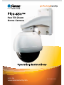
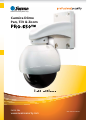
PRO-650™
™
™
Advanced security made easy
Operating Instructions
PRO-650™
™
™
Advanced security made easy
Pan Tilt Zoom
Dome Camera

222
FCC Verification:
NOTE: This equipment has been tested and found to comply with the limits for
Class B digital device, pursuant to part 15 of the FCC Rules. These limits are de-
signed to provide reasonable protection against harmful interference in a residen-
tial installation. This equipment generates, uses and can radiate radio frequency
energy and, if not installed and used in accordance with the instructions, may
cause harmful interference to radio or television reception, which can be deter-
mined by turning the equipment off and on, the user is encouraged to try to cor-
rect the interference by one or more of the following measures:
· Reorient or relocate the receiving antenna
· Increase the separation between the equipment and the receiver
· Connect the equipment into an outlet on a circuit different from that to which
the receiver is connected
· Consult the dealer or an experienced radio/TV technician for help
IMPORTANT NOTE: Prohibition against eavesdropping
Except for the operations of law enforcement officers conducted under lawful
authority, no person shall use, either directly or indirectly, a device operated pursu-
ant to the provisions of this Part for the purpose of overhearing or recording the
private conversations of others unless such use is authorized by all of the parties
engaging in the conversation.
WARNING: Modifications not approved by the party responsible for compliance
could void user’s authority to operate the equipment.
IMPORTANT SAFETY INSTRUCTIONS:
· Make sure product is fixed correctly and stable if fastened in place
· Do not operate if wires and terminals are exposed
2
Before You Begin
FOR BEST RESULTS:
This is a semi-professional 360º PTZ dome camera, conforming to PELCO P/D stand-
ards. To obtain the best image quality, please use a high quality cable, particularly if
the cables required length exceeds 100ft/35m. For the highest video quality, use a
cable with a solid copper inner conductor and shielded with copper braid.

3
Contents
Before You Begin
Before you Begin 2
Table of Contents 3
Quick Reference 3
Overview 4
Package Contents 4
Layout of the Camera and PTZ Controller 5
Layout of Remote Control 6
Connecting the Camera 8
Mounting the Camera 10
Setting the Command Address 12
Configuring the PTZ Controller 12
Connecting Multiple PTZ Systems 13
Operating the Camera 14
Advanced Operation 16
Additional Functions 17
Troubleshooting Guide 18
Technical Specifications 19
Warranty / Technical Support Rear Cover
Quick Reference
PRO-650 4” Pan, Tilt, Zoom Dome
Default PTZ Configuration
Default Command Address: 1
Protocol: Pelco-D
Baud Rate: 2400bps
RS485 Polarity:
+A Purple Wire
- B White Wire

444
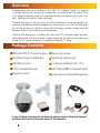
Overview
Congratulations on your purchase of this 360º PTZ Camera Dome! This system
is an ideal solution for monitoring a large area – a combination of a quality Sony
CCD image sensor mounted in a contained dome with the option to pan fully
360º. Nothing will be out of sight for long!
Whether you wish to do this using the full complement of manual controls, or
program a detailed surveillance program for the camera to run, the PRO-650 gives
you all the options you need to simply and effectively monitor a large range of
locations without the hassle of multiple cameras.
The PRO-650 features an included fully functional PTZ controller, great low-light
performance and a 3x optical zoom – great for getting up close to what you want
to see. All this comes mounted in a simple but elegant 4” dome.
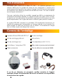
PRO-650 PTZ 4” Dome Camera
Roof Mounting Arm/Bracket
Wall Mount Arm
PTZ Controller/Receiver
Remote Control
Mounting Screws
Operating Instructions
2 x Power Adaptors (DC 12V)
50ft (15m) RS485 Command Cable
Spare Camera Cable & Plug Board
Package Contents
If any of these components are missing, contact Swann Technical Support.
Contact details are on the back cover of this booklet.

55
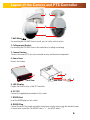
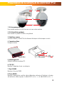
Layout of the Camera and PTZ Controller
1. Wall-Mount Arm
For mounting the PRO-650 Dome to a wall, post or similar vertical surface.
2. Ceiling-mount Bracket
For mounting the PRO-650 Dome to the underside of a ceiling or overhang.
3. Camera Housing
Contains the camera, PTZ unit and associated circuitry and electronic components.
4. Dome Cover
Protects the camera.
4
1. Wall-Mount Arm
1
3
2
5. LED Display
Displays the current status of the PTZ controller.
6. DC 12V
Connect the supplied power adaptor to this socket.
7. RS485 Port
Insert the RS485 plug into this socket.
8. RS485 Plug
Connect the end of the purple and white control wires into this plug, using the attached screws
to secure wires in position. The PURPLE wire is “+”, the WHITE wire is “-”.
8
6
7
Rear View
Front View
5

666
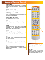
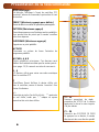
Layout of Remote Control
DISP (Display)
Toggles the display on the front of the PTZ Controller,
showing the Command Address, Protocol and Baud
Rate.
PRESET (HOLD to define)
Changes or accesses preset points.
PATTERN (press and HOLD)
Allows for the programming of lists of preset points for
the camera to view in sequence.
DELETE (press and HOLD)
Will remove a Preset Point or Pattern.
RUN
Commands the system to begin executing the
programmed pattern.
HOME
Master Preset Point. Whilst not in Cruise Mode
(see page 15) the camera will automatically
return to this position whilst idle.
A & B
Master Preset Points. They are defined in the same way
as other Preset Points (see page 14). They operate as
shortcut buttons thereafter.
0 – 9
The number buttons. Used to enter a numerical value
into the PTZ controller.
C
Clear. Removes the last digit entered into the controller,
somewhat like the ‘backspace’ key on your computer.
-/--
Allows for the entry of more than one digit at a time. “-”
represents a single digit, whilst “--” indicates space to
enter two digits.
S1 ~ S4
Shortcut to the SPEED setting for the
camera. 1 is the slowest shortcut speed,
4 is the highest.
P1 ~ P8
Shortcuts to PRESET POSITIONS. Pressing
the button will send the camera directly to
the corresponding PRESET POSITION.
5

7
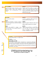
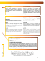
ZOOM + / -: Increases and decreases the level of magnification, respectively.
The PRO-650 features a 3x optical zoom.
FOCUS + / - and
IRIS OPEN / CLOSE
The PRO-650 PTZ Dome features automatic focus and exposure adjustment.
As a result, you will not need to use these buttons whilst operating the PRO-
650. They’ve been included on the remote so that the controller can be used
for multiple PTZ systems (including ones without automatic focus and exposure
adjustment) if you choose.
ARROWS
Used to move the camera.
SHOT
Readies the controller to accept a numerical
value for a Preset Position, noted on the display
by the letter “P”.
CAM
Readies the controller to accept a new
Command Address (use numerical buttons to
enter a new value).
ENTER
Confirms a selection. Whilst the camera is
moving, ENTER will hold it still.
SPEED
Adjusts the speed at which the camera moves.
Higher numbers represent faster speeds.
AUTO
Toggles Auto-scan Mode on and off. Whilst in
Auto-scan Mode, the camera will continually
move as it attempts to sweep the entire field
of view as efficiently as it can.
FOR MORE detailed information about operating
the PTZ features of the PRO-650 Dome, see
Operating the Camera on page 14.
ESC (Escape)
Stops the current action and returns to the
default interface. Aborts half completed
sequences, such as programming a cruise
pattern.
SETUP
Readies the PTZ Controller to accept new
values for Baud Rate and Protocol. The “p”
and “d” are protocols (Pelco-P and Pelco-D
respectively) and the numerical value is the
abbreviated Baud Rate.
S1 ~ S4
Shortcut to the SPEED setting for the
camera. 1 is the slowest shortcut speed,
4 is the highest.
P1 ~ P8
Shortcuts to PRESET POSITIONS. Pressing
the button will send the camera directly to
the corresponding PRESET POSITION.

888
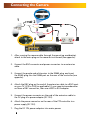
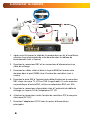
Connecting the Camera
1
2
5
7
4
3
After running the camera cable through the mounting arm/bracket, 1.
attach to the main plug on the camera circuit board (see opposite).
Connect the BNC connector and power connectors to an extension 2.
cable.
Connect the purple and white wires to the RS485 plug, and insert 3.
the RS485 plug into the RS485 port on the rear of the controller (see
opposite).
Attach the BNC plug on the end of the extension cable to a BNC input 4.
on your TV, VCR or DVR (as applicable). If your monitor/recorder does
not have a BNC connection, then use a BNC to RCA adaptor.
Connect the power connector on the end of the extension cable to 5.
the DC plug of a power adaptor (DC 12V).
Attach the power connector on the rear of the PTZ controller to a 6.
power supply (DC 12V).
Plug the DC 12V power adaptors into mains power.7.
6

9
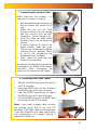
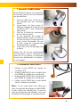
1. Connecting the Camera Cable
Before mounting the camera, it is
important to connect it correctly.
Run the cable through the mounting 1.
arm or bracket you would like to
use.
Make sure you run the cable 2.
through starting with the camera
end (not the end with the BNC
connectors - they’re too big to fit).
Once the cable has been pulled 3.
through, plug it into the top of the
camera.
If you’re planning to mount the 4.
dome outside, cover the screw
threads with a silicon sealant before
screwing the unit together. Failing
to do so will compromise the
waterproofing of the dome.
Then, screw the mounting arm/5.
bracket onto the dome.
Be careful not to damage the connectors
on the end of the cable or to the camera,
particularly when unplugging the
camera, as the connectors are fragile!
3. Connecting the RS485 Cables
Remove the RS485 plug from the back of 1.
the PTZ controller.
Insert the WHITE wire into the -B side of 2.
the RS485 plug, and screw into place.
Insert the PURPLE wire into the +A side of 3.
the RS485 plug, and screw into place.
Plug the RS485 plug into the RS485 port 4.
on the back of the PTZ controller.
Note: If you need a longer cable to reach
the location you’d like to put the PTZ
controller, the RS485 cable can be extended.
If you are unfamiliar with cable construction
and maintenance, we suggest getting a
professional to do this.

101010
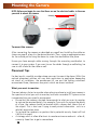
NOTE: Before you begin, be sure that there are no live electrical cables in the area
you wish to mount the camera.
To mount the camera:
After connecting the camera as described on page 8 and installing the cables as
shown on page 9, place it in the desired location. Then, using an appropriate screw
for the surface you’re fixing the dome to, screw the arm/bracket into place.
Ensure you have enough cable coming through the mounting arm/bracket to
connect it to your system. If you want to run the cables through a wall/ceiling, be
sure to drill a hole for the cable as well.
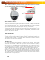
Placement Tips
For best results, carefully consider where you want to mount the dome. Whilst the
optimal placement solution will vary form application to application depending
on intent of installation, the environment of use and the lighting conditions
encountered there, there are a few points which are almost universal.
What you want to monitor:
The most obvious factor to consider when planning where to install your camera is
the question of what you wish to monitor, and how a movable PTZ system can be
incorporated into your specific environment.
Ensure that the camera is located close enough to what you want to monitor •
to capture the required details. For example, if you wish to capture the details
of a face, the camera should be located within a dozen feet (about 4m) of
the subject. This is also true if trying to read printed information - such as a
vehicle’s registration plate.
Try to place the camera in an position that a potential security threat will find •
it difficult to avoid.
A strategy which is often effective is to monitor entrances and exits - after all, •
a security threat has to get in somewhere.
Mounting the Camera

11
Field of view
The PRO-650 can pan a full 360º. This means that (for example) installing the
PRO-650 in a tight corner is probably not an ideal utilization of its potential! A wall
is a better option, as it allows 180º of view for the camera. A freestanding pole
of sufficient height and integrity to reliably hold the camera securely is an ideal
choice, as is the centre of the ceiling in a larger room or a warehouse.
Height
For best results, the PRO-650 PTZ Dome should be mounted as high up as
practicable. This is because the camera has complete freedom of tilt movement
in the 90º below the horizontal plane. Stated more simply, it can see things below
it, but not above! Extensions for the provided mounting hardware are available
through our online store.
Joining Cables
We strongly advise against the modification (i.e. cutting and/or joining) of video
cables. Each cut/join will noticeably reduce video quality, and increase the chances
of the system failing over time. We also advise against using cable joiners/adaptors
to plug multiple cables together. Rather, we suggest using a single unmodified
video cable, chosen in accordance with the guidelines below.
Recommended Cable Length and Type
Being a semi-professional PTZ dome system, the PRO-650 benefits greatly from
being installed using high quality cables to minimise video signal loss. This becomes
particularly important if using a cable longer than approximately 100ft/35m. The
longer the cable used to carry the video signal, the more noticeable the reduction
in video quality will become.
To maximise the quality of the video signal, consider using a high quality video
cable or installing your monitor/recording device closer to the PTZ dome. Of course,
in many circumstances, moving the monitor/recording device is not a viable option;
in these cases, a high quality cable is the best solution.
For optimal results, use a single, unbroken coaxial cable with a solid
copper core and copper braid shielding.
Exposure to Weather
The Pro-650 PTZ Dome is weather and water resistant (rated IP66). However, be
aware that long term exposure to adverse weather conditions (extreme temperature
uctuation, excessive moisture or direct sunlight) may eventually interfere with the
correct operation of the unit.
IMPORTANT: If mounting the camera outside, be sure to properly seal all
joints in the mounting arm/bracket using a silicon sealant. If this is not
fully sealed, water can enter the dome causing malfunction or failure.

121212
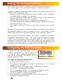
Configuring the PTZ Controller
Setting the Command Address
The included PTZ controller is capable of controlling multiple PTZ cameras. Thus,
each camera needs its own unique identification (a “Command Address”).
To define a camera’s Command Address, connect the camera (and only that
camera) to the PTZ controller. Then:
Press the CAM key. The display will now show Axxx (where “xxx” is the current •
Command Address assigned to the controller).
Enter the Command Address that you’d like to assign to the camera. For •
numbers higher than 10, press the -/-- key first.
Press and hold the PRESET button. The display will change to SET-•
To confirm changes to the Command Address setting, press the SETUP button. •
The display will show –OH–.
The camera’s Command Address has now been changed to your desired •
value.
Please note that if you press the CAM button then enter a number, you are changing
the Command Address in the PTZ controller, but not in any cameras. Holding
PRESET then pressing SETUP applies that address to the connected cameras.
When we define a command address, that address is applied to all cameras
connected to the controller at once. Thus, if you have two cameras connected
to the PTZ controller at once, enter a command address of “005” into the PTZ
controller and press PRESET then SETUP, both cameras will now respond to the
controller on Command Address 005, and cannot be operated individually until
one camera’s Command Address is changed so that both are unique.
Default Settings:
Protocol = Pelco-D
Baud Rate = 2400bps
To ensure that the Controller knows how to
command the PRO-650, we need to make sure
it is using the correct Protocol and Baud Rate. If
these are not set correctly, the PRO-650 will not
operate properly (or at all).
To change the Protocol and Baud Rate:
Press and hold the SETUP button.•
The display on the Controller will change to a letter (either “d” or “p”) and a •
number (12, 24, 48 or 96).
The letter represents the current protocol, either Pelco-P or Pelco-D.•
The number is the abbreviated Baud Rate. •
(i.e. “12” represents 1200bps, “24” represents 2400bps and so on)
Use the UP and DOWN arrows to change the Protocol.•
Use LEFT and RIGHT to change the Baud Rate.•
When set correctly, the letter should be “d” and the number “24”•
Press ENTER to save your changes.•

13
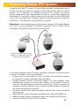
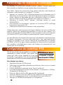
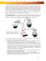
Connecting Multiple PTZ Systems
Connecting multiple PTZ systems to the included controller is a convenient way to
be able to access and control a complex, multi-camera system from one central
location. This is, however, and advanced feature of PTZ systems, and should
only be attempted by those experienced with security system and/or networking
technologies. In a nutshell: multiple systems can be connected to the RS485 cable
in a bus or line configuration. The exact details of the wiring solution will vary by
environment - the following is presented only as a guide.
Please Note: If you already have, or are planning on getting, a PTZ capable Swann
DVR, then using the supplied PTZ controller is optional. The PTZ system can be
controlled by the RS485 connection built into the DVR.
In the above example, three PTZ domes have been connected to the one central
controller. To achieve this wiring arrangement:
Connect the PTZ systems one at a time, and follow the instructions opposite •
to assign each camera a separate command address.
Multiple cameras sharing a command address can cause problems when •
implementing a system. In the best case scenario, two or more PTZ systems
sharing a command address will move synchronously, without the option to
move each camera separately. Often, a shared command address will prevent
the system from operating normally.
Once each camera has a command address defined, they can be connected •
simultaneously.
Take the purple (+) wires, and connect all three to the +A side of the RS485 plug.•
Repeat for white (-) wires, and connect all three to the -B side of the RS 485 plug.•
Connect the RS485 plug to the PTZ controller.•
Diagram showing a potential wiring
solution for integrating multiple PTZ
systems to the one controller.

141414
Operating the Camera
Moving the Camera
The easiest way to move the camera is to use the directional buttons. In the
standard live control mode, the camera will move in the direction of the button
which you press.
To make the camera pan left or right, press and hold the LEFT or RIGHT •
directional button, respectively. You can hold down either button continuously,
the camera will continue to pan left or right (around a circle) indefinitely.
To tilt the camera up and down, use the up and down buttons. Note that whilst •
the camera can pan infinitely, the tilt has only a 90º freedom of movement. It
can see everything that happens below the dome, but not above it.
To make objects in the view appear bigger or smaller use the ZOOM controls.•
Setting a Preset Point
Setting Preset Points allows you to program movements for your camera system
to repeat over time, or to remember a specific viewpoint for easy access later. The
PRO-650 can store up to 16 user-defined Preset Positions.
Using the directional arrow buttons, move the camera into the position that •
you’d like it to store as a Preset Position.
Press the PRESET button on the remote, and hold for two seconds.•
The display will now read “SET-”•
Press a number key to assign a Preset number to the position. To define a •
Preset Position with a value higher than 10, press the -/-- button first.
The information in this section assumes that you have the PRO-650 attached
to the supplied IR receiver/PTZ Controller module and have followed the
instructions on page 10 for configuring the Command Address, Protocol
and Baud Rate settings.
Alternately, if you have the RS485 connections to the PRO-650 attached to a
PTZ capable DVR, then use the PTZ controls through your DVR (consult your DVR
manual for more details).
Accessing a Preset Point
The easiest way to access the preset points, use the shortcut buttons, marked P1
through P8. Of course, this only works for the first eight Presets. To access Preset
9 and above:
Press the SHOT button.•
If you’re accessing a point above 10, press the -/-- button.•
Enter the number of the Preset you’d like to access.•
Press ENTER to confirm.•

15
Removing a Preset Point
Removing Preset Points is performed in much the same manner as defining them.
Once a Preset Point has been removed, selecting it as detailed opposite will no
longer have any effect, until a new point is set.
Press the DELETE button on the remote, and hold for two seconds.•
The display will now read “Clr-”•
Press a number key to select a Preset Point number. To choose a Preset Point •
with a value higher than 10, press the -/-- button first.
Press ENTER to confirm.•
The selected Preset Point will now no longer be set.•
Cruise Mode
Whilst the PRO-650 is in Cruise Mode, the camera will move continuously and
automatically, only pausing when it arrives at Preset Points for a short interval.
There are two ways to enter Cruise mode.
Auto-scan (Cruise) Mode
When in Auto-scan Mode, the PRO-650 will continuously move automatically,
attempting to observe as much of the field of view as practicable in the shortest
time it can.
To enter Auto-scan Mode, press AUTO.•
For an alternate Auto-scan mode, go to Preset Point 99.•
Manual Cruise Mode
You can program lists of Preset Points for the PRO-650 to view in order.
First, create all the Preset Points you wish to see, as detailed on page 8.•
Press and hold PATTERN for two seconds. •
The display will now read “PStA”.•
Press the NUMBER button for the first Preset Point you want in the programmed •
loop, using the -/-- button to access points higher than 10 if necessary.
Press ENTER once the camera has moved to that Preset Point to confirm.•
Repeat for the other Preset Points you want on the loop, in the order that you •
want them to be accessed. Remember to press ENTER each time to confirm
your selection.
Press and hold PATTERN for two seconds. The display will now show “PSt0” •
confirming that the pattern programming has ended and the pattern has been
saved.
Press RUN to initiate the programmed pattern, and press RUN again to stop •
the pattern.
To reset the Cruise Mode settings to their default values, press PRESET followed •
by -/--, and enter “240”.

161616
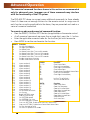
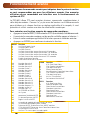
Advanced Operation
The numerical command functions shown in this section are recommended
only for advanced users. Improper use of these commands may interfere
with the functionality of the PTZ system.
The PRO-650 PTZ dome can accept many additional commands to those already
listed. As there are not enough buttons on the remote control to assign one to
each function or setting applicable to the dome, they are presented and used as a
series of numerical commands.
To execute an advanced numerical command function:
Press the PRESET, CLEAR or GOTO button (as applicable) on the remote control.•
As all numerical commands are more than a single digit, press the -/-- button.•
Enter the applicable numerical code for the function you wish to execute. •
Press ENTER to confirm and execute the function.•
PRESET Function
62 Set Left limited point
63 Set Right limited point
76 Set Home Point
77 Set Home Point Wait Time to 64 seconds
78 Set Home Point Wait Time to 128 seconds
79 Set Home Point Wait Time to 192 seconds
80 Set Home Point Wait Time to 255 seconds
81 Enable Auto-Home function
82 Disable Auto-Home function
224 Input number 0
225 Input number 1
226 Input number 2
227 Input number 3
228 Input number 4
229 Input number 5
230 Input number 6
231 Input number 7
232 Input number 8
233 Input number 9
234 Input number 10
235 Input number 11
236 Input number 12
237 Input number 13
238 Input number 14
239 Input number 15
240 Init EEPROM to Default
241 Init System
242 Begin PATTERN setup
243 End PATTERN setup
244 Set PATTERN speed
245 Set PATTERN stay time
246 Set PATTERN point number
247 Start run PATTERN, Enable Auto Start PATTERN cruise
248 Stop run PATTERN, Disable Auto Come Back Home Point
249 Set Pan Limited to 0x38
255 Set Pan/Tilt speed to fast mode
CLEAR Function
1 -- 32 Clear Preset Point
62 Clear Left Limited Point
63 Clear Right Limited Point
76 Clear Home Point
81 Disable Auto Come Back Home Point
92 Clear Left Limited Point
93 Clear Right Limited Point;
240 Init Pan Tilt to Default
249 Set Pan Limited to 0x3F
GOTO Function
1 -- 32 Goto Preset Point
34 Goto Pan Zero point
62 Goto Left Limited Point
63 Goto Right Limited Point
76 Goto Home Point
92 Goto Left Limited Point
93 Goto Right Limited Point
96 Stop Auto Scan
99 Start Auto Scan

17
Additional Functions
Auto-Home Function
The PRO-650 can be configured to automatically return to it’s master Preset Point,
the “Home Point”. This is particularly useful for monitoring a door, hallway, car
space or similar, where the default position of the camera should be viewing this
location.
To turn Auto-Home ON and OFF use the numerical command shown opposite.
The numerical commands are “81” to enable the Auto-Home function, and “82”
to disable it. You can also change the wait time (the amount of time the camera
will spend stationary before defaulting to the home point) by using numerical
shortcuts 77 - 80.
The Home Point is stored as PRESET 76. Defining this Preset Point will redefine
the Home Point. To remove the Home Point, follow the instructions for deleting a
Preset Point, and DELETE Preset Point 76.
F1 - F4 Shortcut Buttons
These are user-defined buttons, which can be used as master shortcut buttons.
Defining the behaviour of shortcut buttons is complex, and not recommended
for novice or intermediate users. Proper usage of the shortcut interface requires
detailed knowledge of PELCO-P/D protocols. In this example, we’ll set F1 to be a
shortcut key to access Preset Point 8. The PELCO command for this operation is:
0x00 0x07 0x00 0x08.
Press the SHOT button, followed by -/--. Key in “240” and press ENTER.•
The LED display will now show “0---”•
Input X, where X is the F button you wish to assign the shortcut to. In this •
example, as we want to define F1, enter “1” and press ENTER.
The display will now show “1---”. In this example, we wish to enter “0” •
(abbreviation of 0x00 in hexadecimal).
The display will now show “2---”. Continuing the above example, enter “7” and •
press ENTER.
The display will now show “3---”. Enter “0”, press ENTER.•
The display will now show “4---”. Enter “8”, press ENTER.•
Once this has been defined, pressing F1 will instantly take the camera to Preset Point 8.
To create other customised shortcut programs you’ll need a list of commands for PTZ
protocols. These are easily obtained via the Internet - just enter the protocol you’d like
into a good search engine and you’ll find several lists compiled by different authorities.
The specific protocol you’ll use depends on your needs and limitations of your specific
setup. If in doubt, we suggest hiring an experience installer/technician.

181818
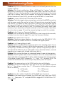
Troubleshooting Guide
Problem: My DVR is in Motion Detection mode, and continually records whilst the
camera is moving.
Solution: This is not a malfunction. When a DVR looks for “motion”, what it is
really doing is looking for a change between one image it captures and the next.
Therefore, it doesn’t matter whether it’s something the camera sees or the camera
itself that is moving, the DVR will interpret the change as movement. Turn off
Motion Detection on your DVR if you are using the PRO-650 in Cruise Mode.
Problem: I cannot control the PTZ features of the camera.
Solution: Check the integrity of your connections, particularly the RS485 connection
and the power supply. Be sure the (+A) and (-B) terminals are connected the right
way around. If this does not help, then the PTZ settings in your controller may be
set incorrectly. Check the Command Address, Protocol (Default: Pelco-D) and Baud
Rate (Default: 2400 bps) settings in your PTZ controller, and correct them where
necessary. If you have only one camera attached to the PTZ controller, then follow
the instructions on page 10 to set the camera’s settings to match the controller.
Problem: I don’t know my Command Address!
Solution: You can either go through them one at a time to see which one works,
or follow the instructions on page 10 to reset the Command Address.
Problem: The camera won’t turn on.
Solution: Check your power adaptor is the right one for the PRO-650 (DC 12V).
Make sure both the camera and the PTZ controller are supplied power.
Problem: I can’t see anything at night.
Solution: Whilst the PRO-650 has great low-light vision (needing only 0.01 Lux)
it does need some light. If used in a pitch-black environment, it will not be able to
see anything. Consider illuminating your subject - perhaps simply leaving a light on
will make all the difference. If you really need to see in absolute darkness, consider
upgrading to a camera with infrared night-vision built in.
Problem: After running the dome for an extended period, it seems to lose precision.
Solution: The PTZ system needs to be re-initialized - this is the same procedure the
dome undertakes when turned ON. To do this, either disconnect and reconnect power
to the dome, or press PRESET followed by “-/--”, input “241” and press ENTER. The
camera will re-calibrate itself, and accuracy of the pan/tilt system will improve.
Problem: The camera returns to the HOME position too quickly/slowly.
Solution: Change the HOME point wait time. To do this, press PRESET followed
by “-/--”. Then, enter a number from 77 - 80 based on the table below, and press
ENTER to confirm.
77 = 64 Seconds 79 = 192 Seconds
78 = 128 Seconds 80 = 255 Seconds
Problem: How do I enable / disable the AUTO HOME point function?
Solution: In the same way as changing the HOME point wait time. Press PRESET
then “-/--”. Then, enter “81” and press ENTER to toggle AUTO HOME ON or “82”
to turn it OFF.

19
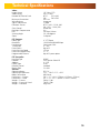
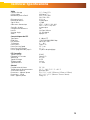
Technical Specifications
Video
Image Sensor 1/3” Sony CCD
Video Quality 420 TV Lines
Number of Effective Pixels NTSC: 510 x 492
PAL: 500 x 582
Minimum Illumination 0.01 Lux
White Balance Automatic
Signal / Noise Ratio > 50dB
Electronic Shutter NTSC: 1/60 – 1/100, 000
PAL: 1/50 – 1/100, 000
Gain Control Automatic
Backlight Compensation Yes
Lens Vari-focal 4-9mm
Viewing Angle 30 – 60 degrees
Zoom 3x Optical
PTZ Features
Dome Type 4” PTZ Dome
Baud Rate 1200/2400/4800/9600 bps
Pan Rotation Continuous 360º
Tilt Rotation 0º ~ 90º
Preset Points Up to 32
Preset Panning Speed 35º/sec
Preset Panning Accuracy + / - 3º
Programmable Pattern Up to 32 preset points
PTZ Controller
Interface Type RS485
Protocol Full Function Pelco P/D
Address 0 – 255
Display Type 4 LED
Remote Control Included
Battery Type 2 x AAA
General
Operating Power DC 12V
Operating Temperature 23ºF ~ 140ºF / -5ºC ~ 60ºC
Body Construction ABS Plastic
Dimensions – Camera 5.9” x 3.1” x 4.9” (150mm x 125mm x 125mm)
Dimensions – Stand 4.5” x 3.1” x 5.3” (80mm x 72mm x 28mm)
Weight – Camera 500g / 1.1lbs
Weight – Camera & Stand 700g / 1.5lbs
Weight – Controller 85g / 3oz

202020
© Swann Communications 2009
Advanced security made easy™
Swann Communications warrants this product against defects in workmanship and material
for a period of one (1) year from it’s original purchase date. You must present your receipt
as proof of date of purchase for warranty validation. Any unit which proves defective during
the stated period will be repaired without charge for parts or labour or replaced at the sole
discretion of Swann. The end user is responsible for all freight charges incurred to send the
product to Swann’s repair centres. The end user is responsible for all shipping costs incurred
when shipping from and to any country other than the country of origin.
The warranty does not cover any incidental, accidental or consequential damages arising
from the use of or the inability to use this product. Any costs associated with the fitting or
removal of this product by a tradesman or other person or any other costs associated with
its use are the responsibility of the end user. This warranty applies to the original purchaser
of the product only and is not transferable to any third party. Unauthorized end user or
third party modifications to any component or evidence of misuse or abuse of the device will
render all warranties void.
By law some countries do not allow limitations on certain exclusions in this warranty. Where
applicable by local laws, regulations and legal rights will take precedence.
Swann Communications USA Inc.
12636 Clark Street
Santa Fe Springs CA 90670
USA
Swann Communications PTY. LTD.
Building 4, 650 Church Street,
Richmond, Victoria 3121
Australia
Warranty Information
Swann Technical Support
All Countries E-mail: tech@swannsecurity.com
Telephone Helpdesk
See http://www.worldtimeserver.com for information on time zones and the
current time in Melbourne, Australia compared to your local time.
USA toll free
1-800-627-2799
(Su, 2pm-10pm US PT)
(M-Th, 6am-10pm US PT)
(F 6am-2pm US PT)
USA Exchange & Repairs
1-800-627-2799 (Option 1)
(M-F, 9am-5pm US PT)
AUSTRALIA toll free
1300 138 324
(M 9am-5pm AUS ET)
(Tu-F 1am-5pm AUS ET)
(Sa 1am-9am AUS ET)
NEW ZEALAND toll free
0800 479 266
INTERNATIONAL
+61 3 8412 4610
Help Desk and Technical Support
La page est en cours de chargement...
La page est en cours de chargement...
La page est en cours de chargement...
La page est en cours de chargement...
La page est en cours de chargement...
La page est en cours de chargement...
La page est en cours de chargement...
La page est en cours de chargement...
La page est en cours de chargement...
La page est en cours de chargement...
La page est en cours de chargement...
La page est en cours de chargement...
La page est en cours de chargement...
La page est en cours de chargement...
La page est en cours de chargement...
La page est en cours de chargement...
La page est en cours de chargement...
La page est en cours de chargement...
La page est en cours de chargement...
La page est en cours de chargement...
-
 1
1
-
 2
2
-
 3
3
-
 4
4
-
 5
5
-
 6
6
-
 7
7
-
 8
8
-
 9
9
-
 10
10
-
 11
11
-
 12
12
-
 13
13
-
 14
14
-
 15
15
-
 16
16
-
 17
17
-
 18
18
-
 19
19
-
 20
20
-
 21
21
-
 22
22
-
 23
23
-
 24
24
-
 25
25
-
 26
26
-
 27
27
-
 28
28
-
 29
29
-
 30
30
-
 31
31
-
 32
32
-
 33
33
-
 34
34
-
 35
35
-
 36
36
-
 37
37
-
 38
38
-
 39
39
-
 40
40


Swann PRO-650 Operating Instructions Manual
- Catégorie
- Des caméras de sécurité
- Taper
- Operating Instructions Manual
- Ce manuel convient également à
dans d''autres langues
- English: Swann PRO-650
Documents connexes
Autres documents
-
FLIR C346ZC252 Manuel utilisateur
-
NIGHT OWL AHD10 Series Guide d'installation rapide
-
Lorex LZV2925SB Manuel utilisateur
-
Samsung SCC-C7325 Manuel utilisateur
-
Samsung SCC-C7478P Manuel utilisateur
-
-
-
Comelit IPPTZ120IR Manuel utilisateur
-
-
Centurion TB-CN3R1 Manuel utilisateur