
Remote
Control
NTX-RC
Please read this
manual BEFORE
installing your
remote control
Owner's
Manual

2 | SAMLEX AMERICA INC.
OWNER'S MANUAL | Index
SECTION 1
Introduction ......................................................................... 3
SECTION 2
Layout .......................................................................... 4
SECTION 3
Display .......................................................................... 5
SECTION 4
Operation .......................................................................... 8
SECTION 5
Specications ....................................................................... 8
SECTION 6
Warranty .......................................................................... 9
Disclaimer of Liability
UNLESS SPECIFICALLY AGREED TO IN WRITING, SAMLEX AMERICA, INC.:
1. MAKES NO WARRANTY AS TO THE ACCURACY, SUFFICIENCY OR SUITABILITY OF ANY TECHNICAL OR OTHER
INFORMATION PROVIDED IN ITS MANUALS OR OTHER DOCUMENTATION.
2. ASSUMES NO RESPONSIBILITY OR LIABILITY FOR LOSSES, DAMAGES, COSTS OR EXPENSES, WHETHER SPECIAL,
DIRECT, INDIRECT, CONSEQUENTIAL OR INCIDENTAL, WHICH MIGHT ARISE OUT OF THE USE OF SUCH INFORMA-
TION. THE USE OF ANY SUCH INFORMATION WILL BE ENTIRELY AT THE USERS RISK.
Samlex America reserves the right to revise this document and to periodically make changes to the
content hereof without obligation or organization of such revisions or changes.
Copyright Notice/Notice of Copyright
Copyright © 2019 by Samlex America, Inc. All rights reserved. Permission to copy, distribute and/or
modify this document is prohibited without express written permission by Samlex America, Inc.

2 | SAMLEX AMERICA INC. SAMLEX AMERICA INC. | 3
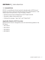
SECTION 1 | Introduction
1.1 DESCRIPTION
NTX-RC is a wired Remote Control used with selected models of NTX Series of
Inverters to switch on and switch off the Inverter from a remote location. It also
displays operational parameters using LCD display as follows:
• Numerical value of input voltage seen at the DC input terminals
• Bar graph to depict output power level
• Flashing fault messages: "Input Fault" and "Output Fault"
Applicable Models of NTX Inverters
NTX-RC Remote Control is designed to work with the following models of the
NTX Series:
• NTX-1000-12
• NTX-1500-12
• NTX-2000-12
• NTX-3000-12

4 | SAMLEX AMERICA INC.
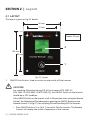
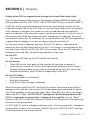
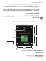
2.1 LAYOUT
The layout is given at Fig 2.1 below.
82 mm
72 mm
102 mm
92 mm
2
1
Fig. 2.1 Layout
Depth: 35 mm
1. ON/OFF Push Button. Used to switch on and switch off the Inverter.
!
CAUTION!
For switching ON and switching OFF of the Inverter (NTX-1000-12/
NTX-1500-12 / NTX-2000-12/ NTX-3000-12), the ON/OFF Switch on the Inverter
should be in OFF condition.
If the ON/OFF Switch on the Inverter is left in ON position when using the Remote
Control, the following will be observed on pressing the ON/OFF Button on the
Remote Control (1 in Fig 2.1) for switching ON and Switching OFF the Inverter:
• Press ON/OFF Button (1 in Fig 2.1) to switch ON the Inverter: The Remote
Control will display the status of operation of the Inverter
SECTION 2 | Layout

4 | SAMLEX AMERICA INC. SAMLEX AMERICA INC. | 5
SECTION 3 | Display
• Press ON/OFF Button (1 in Fig 2.1) to Switch OFF the Inverter: The LCD
Display (2 in Fig 2.1) will switch OFF. However, the Inverter will not switch
OFF and the batteries will continue to drain due to the following energy
consumption:
(i) Due to the “no load draw” of the inverter if no load is present or due
to the DC side current draw if AC load is present
(ii) Due to the power drawn by the fans (the fans in the Inverter run
continuously as long as the inverter is in ON condition)
2. LCD display
3. (Not shown. Located at the back of the Remote). 8P8C (8 Position, 8 Conductor)
Modular Connector Receptacle (also known as RJ-45 Receptacle) used for
connecting the Remote Control to the Inverter with the help of 10', Cat 5, 8
conductor cable.
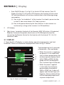
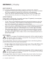
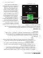
3.1 DISPLAY
A Green backlit LCD display is used to display operational parameters and fault
conditions. Details of information displayed are shown at Fig 3.1 below:
The backlighting has 2 intensities
of brightness – dim and bright:
• When the inverter is supplying
no power (is in no load condi-
tion) or lower power below the
minimum power display thresh-
old of 50W to 100W, the bar
graph will NOT be displayed.
Also, the back-light will be dim
• When the power supplied
is more than the minimum
power display threshold of
50W to 100W, the 1st bar will
appear and the back-light will
brighten. More number of bars
will be displayed proportional
to power output level.
Fig. 3.1 Details of LCD Screen
1
2
3
4

6 | SAMLEX AMERICA INC.
SECTION 3 | Display
INPUT VOLTAGE (1)
Input voltage is displayed using 3-digit, 7-segment numerals with 1 decimal:
• Displays 88.8 momentarily during booting process when the remote is switched
ON. After completion of booting, the actual value will be displayed.
• Please note that the displayed voltage will be lower than the voltage at the
battery terminals by the amount of voltage drop in the DC side input wires.
OUTPUT POWER (2)
Output power is displayed by a bar graph consisting of 14 gradually increasing bars
for depicting increasing output power level.
• All the 14 bars will be displayed momentarily during booting process when the
remote is switched on. After completion of booting process, the actual power
level will be displayed by the appropriate number of bars
• When the inverter is supplying no power (is in no load condition) or lower power
below the minimum power display threshold of 100W to 200W depending on
which model, bar graph will not be displayed. Also, the back-light will be dim
• When the power supplied is more than the minimum power display threshold
of 100W to 200W depending on which model, the 1st bar will appear and the
back-light will brighten. More number of bars will be displayed proportional to
power output level.
INPUT FAULT (3)
!
NOTE: This message will be displayed momentarily (will be steady) during the
boot process when the remote is switched ON. The message will ash during
the actual output fault condition
This message ashes when the inverter has shut down due to the following (Please
read the inverter manual for causes and remedies):
• DC input voltage at the terminals of the inverter is low: 10.5 +/- 0.3V VDC or lower
• DC input voltage at the inverter terminals is high: 16.3 +/- 0.3V VDC or higher
• Over temperature
OUTPUT FAULT (4)
!
NOTE: This message will be displayed momentarily (will be steady) during the
boot process when the remote is switched ON. The message will ash during
the actual output fault condition.
This message ashes when the inverter shuts down due to over load or short circuit
on the AC output side (Please read the inverter manual for causes and remedies):

6 | SAMLEX AMERICA INC. SAMLEX AMERICA INC. | 7
Display when GFCI has tripped due to leakage on the Load Side (output side)
The AC output power of the inverter is fed through a Duplex NEMA5-20 outlet with
GFCI protection for NTX-1000-12,NTX-1500-12, NTX-2000-12 only, not for NTX-3000-12.
A GFCI has a relay operated mechanical switch that mechanically switches off the
Load Side (output side) of the GFCI from its Line Side (input side) in case of a ground
fault / leakage. It compares the current sent to the load side and returned back
from the load side. If the returned current is less by more than 5 to 7 mA (this loss of
returned current will be due to ground fault / leakage on the load side), the switch
trips and disconnects the AC load from the AC source. When the GFCI has tripped due
to ground fault / leakage, it can be reset by pressing the reset button.
For the reset button to operate and reset the GFCI, AC power is required to be
present on the Line Side (input side) of the GFCI. If AC power is not available on the
Line Side (input side) of the GFCI, the GFCI will not reset. When the GFCI trips due to
leakage on the Load Side, the following symptoms will be seen:
On the GFCI
• The Green LED light on the GFCI will be switched off
On the Inverter
• Green LED on the front panel of the inverter will continue to remain lit
• Internally, the inverter will still be working normally and the rated AC output
voltage will be available on the internal Line Side of the GFCI, but not on the
external Load Side of the FGCI due to tripped relay in the GFCI.
On the LCD Display
• Power bar graph is switched off
• Backlight is dimmed
• Only the DC input voltage is displayed
When the output side of the GFCI outlet of the inverter trips due to ground fault /
leakage on the load side, the inverter will still be operating normally and AC power
will still be available on the Line Side (input side) of the GFCI (but not on the output
side of the GFCI). Thus, “OUTPUT FAULT” message will NOT be displayed when the
GFCI has tripped due to ground fault / leakage on the Load Side. Use the “Reset”
button on the GFCI to reset the mechanical switch to the ON position after removing
the cause of the ground fault.
For NTX-3000-12, built in leakage protection circuit. Due to ground fault / leakage on
the Load Side, inverter will shut down, Red LED light and "OUTPUT FAULT" message
will be displayed on the remote control.
SECTION 3 | Display

8 | SAMLEX AMERICA INC.
SECTION 5 | Specications
NOTE: Specications are subject to change without notice.
MODEL NO. NTX-RC
APPLICABLE MODELS OF INVERTERS NTX-1000-12, NTX-1500-12, NTX-2000-12, NTX-3000-12
RECEPTACLE FOR
CONNECTING CABLE
8P8C (8 Position, 8 Conductor)
Modular Receptacle (RJ-45)
CONNECTING CABLE TYPE
8 Conductor,
Cat 5 Networking Cable
CONNECTING CABLE TERMINALS 8P8C (8 Position, 8 Conductor) Modular Plug (RJ-45)
TYPE OF CONNECTION Straight
CONNECTING CABLE, LENGTH 3 meters / 10'
DIMENSIONS (WITHOUT CABLE),
MM (L
x W x H)
102 x 82 x 35
DIMENSIONS (WITHOUT CABLE),
IN (L
x W x H)
4.0 x 3.2 x 1.4
WEIGHT (WITHOUT CABLE), KG 0.056
WEIGHT (WITHOUT CABLE), LB
0.12
The Remote Control is provided with 3 meter / 10 ft. length of Cat 5, Straight,
Networking Cable with 8P8C (8 Position, 8 Conductor) Modular Plugs (RJ-45) on either
ends . Plug one end of the cable to the receptacle on the Remote Control (3). Locate
the 8P8C (8 Position, 8 Conductor) Modular Receptacle (RJ-45) on the inverter and
securely insert the other end of the plug on the Remote Control cable. For switching
on and switching off the Inverter using this Remote Control, the Main ON / OFF
Switch on the Inverter should be in the OFF condition.
!
CAUTION! If the ON / OFF Switch on the Inverter is left in ON position,
the Inverter cannot be switched off using this Remote Control. The Remote
Control will, however, continue to display the status of operation.
Please see under “Section 3 - Display” for display information.
SECTION 4 | Operation

8 | SAMLEX AMERICA INC. SAMLEX AMERICA INC. | 9
SECTION 6 | Warranty
2 YEAR LIMITED WARRANTY
NTX-RC manufactured by Samlex America, Inc. (the “Warrantor“) is warranted to be
free from defects in workmanship and materials under normal use and service. The
warranty period is 2 years for the United States and Canada, and is in effect from the
date of purchase by the user (the “Purchaser“).
Warranty outside of the United States and Canada is limited to 6 months. For a
warranty claim, the Purchaser should contact the place of purchase to obtain a Return
Authorization Number.
The defective part or unit should be returned at the Purchaser’s expense to the
authorized location. A written statement describing the nature of the defect, the date
of purchase, the place of purchase, and the Purchaser’s name, address and telephone
number should also be included.
If upon the Warrantor’s examination, the defect proves to be the result of defective
material or workmanship, the equipment will be repaired or replaced at the Warrantor’s
option without charge, and returned to the Purchaser at the Warrantor’s expense.
(Contiguous US and Canada only)
No refund of the purchase price will be granted to the Purchaser, unless the Warrantor
is unable to remedy the defect after having a reasonable number of opportunities to do
so. Warranty service shall be performed only by the Warrantor. Any attempt to remedy
the defect by anyone other than the Warrantor shall render this warranty void. There
shall be no warranty for defects or damages caused by faulty installation or hook-up,
abuse or misuse of the equipment including exposure to excessive heat, salt or fresh
water spray, or water immersion.
No other express warranty is hereby given and there are no warranties which extend
beyond those described herein. This warranty is expressly in lieu of any other expressed
or implied warranties, including any implied warranty of merchantability, tness for the
ordinary purposes for which such goods are used, or tness for a particular purpose, or
any other obligations on the part of the Warrantor or its employees and representatives.
There shall be no responsibility or liability whatsoever on the part of the Warrantor or
its employees and representatives for injury to any persons, or damage to person or
persons, or damage to property, or loss of income or prot, or any other consequential
or resulting damage which may be claimed to have been incurred through the use or
sale of the equipment, including any possible failure of malfunction of the equipment,
or part thereof. The Warrantor assumes no liability for incidental or consequential
damages of any kind.
Samlex America Inc. (the “Warrantor”)
www.samlexamerica.com

Contact
Information
Toll Free Numbers
Ph: 1 800 561 5885
Fax: 1 888 814 5210
Local Numbers
Ph: 604 525 3836
Fax: 604 525 5221
Website
www.samlexamerica.com
USA Shipping Warehouses
Kent, WA
Plymouth, MI
Canadian Shipping Warehouse
Delta, BC
Email purchase orders to
11002-NTX-RC-1219-EN

11002-NTX-RC-1219-FR
Information
Contact
Numéros gratuits
Tel: 1 800 561 5885
Fax: 1 888 814 5210
Numéros locaux
Tel: 604 525 3836
Fax: 604 525 5221
Site internet
www.samlexamerica.com
Entrepôts USA
Kent, WA
Plymouth, MI
Entrepôt Canadian
Delta, BC
Adresse email pour
passer commande

8 | SAMLEX AMERICA INC. SAMLEX AMERICA INC. | 9
SECTION 6 | Warranty
GARANTIE LIMITEE SOUS 2 ANS
NTX-RC fabriqués par Samlex America, Inc. (le « Garant ») sont garantis être non défectueux
dans la conception et dans les matériaux, moyennant une utilisation et un service normaux.
La période de garantie est de 2 ans pour les Etats-Unis et le Canada, et prend effet le jour de
l’achat par l’utilisateur (« l’Acheteur »).
La garantie hors des Etats Unis et du Canada est limitée à 6 mois. Pour une réclamation
concernant la garantie, l’Acheteur devra contacter le point de vente ou l’achat a été effectué
an d’obtenir un Numéro d’Autorisation pour le Retour.
La pièce ou l’unité défectueuse devra être retournée aux frais de l’acheteur au point de vente
agrée. Une déclaration écrite décrivant la nature du défaut, la date et le lieu d’achat ainsi que le
nom, l’adresse et le numéro de téléphone de l’Acheteur devront également être renseignés.
Si a l’examination de la demande par le Garant, le défaut est réellement le résultat d’un
matériau ou d’un assemblage défectueux, l’équipement sera réparé ou remplacé gratuitement
et renvoyé a l’Acheteur aux frais du Garant. (Etats-Unis et Canada uniquement).
Aucun remboursement du prix d’achat ne sera accorde a l’Acheteur, sauf si le Garant est incapable
de remédier au défaut après avoir eu plusieurs occasion de le faire. Le service de garantie doit
être effectue uniquement par le Garant. Toute tentatives de remédier au défaut par quelqu’un
d’autre que le Garant rendent cette garantie nulle et sans effet. Il n’existe aucune garantie
concernant les défauts ou dommages causés par une installation défectueuse ou inadaptée, par
un abus ou une mauvaise utilisation de l’équipement, y compris, une exposition excessive a la
chaleur, au sel, aux éclaboussures d’eau fraiche ou a l’immersion dans l’eau.
Aucune autre garantie express n’est accordée et il n’existe aucunes garanties qui s’étendent
au delà des conditions décrites par la présente. Cette garantie est la seule garantie valable et
reconnue par le Garant, et prédomine sur d’autres garantie implicites, y compris les garanties
implicites liées a la garantie de qualité marchande, a l’usage des objectifs habituels pour
lesquels de telles marchandises sont utilisées, ou l’usage pour un objectif particulier, ou toutes
autres obligations de la part du Garant ou de ses employés et représentants.
Il ne doit pas exister de responsabilité ou autre de la part du Grant ou des ses employés et
représentants, en ce qui concerne les blessures corporelles, ou les dommages de personne a
personne, ou les dégâts sur une propriété, ou la perte de revenus ou de bénéces, ou autres
dommages collatéraux, pouvant être rapportés comme ayant survenus au cours de l’utilisation
ou de la vente du matériel, y compris tous disfonctionnements ou échecs du matériel, ou
une partie de celui-ci. Le Garant n’assume aucune responsabilité concernant toutes sortes de
dommages accidentels ou indirects.
Samlex America Inc. (le « Garant »)
www.samlexamerica.com

8 | SAMLEX AMERICA INC.
/ de fuite sur le côté charge. Utilisez le bouton "Reset" sur le GFCI pour réinitialiser le
commutateur mécanique à la position ON après avoir enlevé la cause du défaut à la terre.
Pour NTX-3000-12, circuit de protection contre les fuites intégré. En raison d'un
défaut à la terre / d'une fuite côté charge, l'onduleur s'arrête, le voyant LED rouge et
le message "SORTIE DEFAUT" s'afchent sur la télécommande.
La télécommande est fournie avec 3 mètres / 10 pieds de longueur de Cat 5, droit,
câble réseau avec 8P8C (8 Position, 8 conducteur) Fiches modulaires (RJ-45) sur les
deux extrémités. Branchez une extrémité du câble à la prise de la télécommande (3).
Localisez le 8P8C (8 Position, 8 conducteur) Prise modulaire (RJ-45) sur l'onduleur et
en toute sécurité insérez l'autre extrémité de la che sur le câble de la télécommande.
Pour allumer et éteindre l'onduleur à l'aide de cette télécommande, le principal ON /
OFF sur le variateur doit être dans l'état OFF.
!
ATTENTION ! Si l'interrupteur ON / OFF sur l’onduleur est laissé en position
ON, l’onduleur ne peut pas être désactivée à l'aide de cette télécommande.
La Télécommande continuent toutefois d'afcher l'état de fonctionnement.
S'il vous plaît voir la «Section 3 - Déploie" pour plus d’informations sur le déploie.
SECTION 4 | Opération
REMARQUE : Les spécications sont sujettes à modication sans préavis
MODÉLE NO. NTX-RC
MODÈLE APPLICABLE D’ONDULEUR NTX-1000-12, NTX-1500-12, NTX-2000-12, NTX-3000-12
PRISE POUR LE CÂBLE DE
RACCORDEMENT
8P8C (8 Position, 8 Conducteur)
Prise modulaire (RJ-45)
TYPE DE CÂBLE DE RACCORDEMENT 8 Conducteur, Cat 5 câble réseaux
BORNE DE CÂBLE DE RACCORDEMENT
8P8C (8 Position,
8 Conducteur) Prise modulaire (RJ-45)
TYPE DE CONNECTIONS Droit
CÂBLE DE RACCORDEMENT, LONGUEUR 3 mèters / 10'
DIMENSION (SANS CÂBLE)
MM (L X W X H)
102 x 82 x 35
DIMENSION (SANS CÂBLE)
IN (L X W X H)
4.0 x 3.2 x 1.4
POIDS (SANS CÂBLE), KG 0.056
POIDS (SANS CÂBLE), LB
0.12
POIDS (SANS CÂBLE), LB 0.056
0.12
SECTION 5 | Spécications

6 | SAMLEX AMERICA INC. SAMLEX AMERICA INC. | 7
Ce message clignote lorsque l'onduleur est arrêté en raison d’excès de charge ou court-circuit
a la sortie CA. (Veuillez lire le mode d’emploi de l’onduleur pour les causes et les remèdes) :
Afchage lors de GFCI s'est déclenché en raison d'une fuite sur le côté charge (côté sortie)
La puissance de sortie CA de l'onduleur est installée à travers la prise Duplex NEMA5-
20 avec protection GFCI pour NTX-1000-12,NTX-1500-12, NTX-2000-12 uniquement,
pas pour NTX-3000-12.
Le GFCI a une commande mécanique qui coupe le courant du côté charge (côté sortie)
du GFCI de la côté ligne (côté entrée) au moyen d’un relais en cas de défaut à la terre
/ de fuite. Il compare le courant envoyé au côté charge et retourné du côté charge.
Si le courant de retour est inférieure de plus de 5 à 7 mA (cette perte de courant de
retour sera due à défaut à la terre / de fuite sur le côté de la charge), le commutateur
se déclenche et déconnecte la charge CA de la source CA. Lorsque le disjoncteur est
déclenché suite à défaut à la terre / de fuite, il peut être remis à zéro en appuyant sur le
bouton de réinitialisation.
Pour faire fonctionner le bouton de réinitialisation pour réinitialise le GFCI, L’alimentation
CA doit être présent sur le côté ligne (côté entrée) du GFCI. Si l'alimentation CA n'est pas
disponible sur le côté ligne (côté entrée) du GFCI, le GFCI ne se réarme pas.
Lorsque le GFCI se déclenche en raison d'une fuite sur le côté charge, les symptômes
suivants seront vus :
Sur le GFCI
• L’afchage LED vert sur le GFCI sera éteint
Sur l'onduleur
• L’afchage LED vert sur la face du panneau de l'onduleur continuera à rester allumé
• Sur le plan intérieur, l'onduleur fonctionnera normalement et la tension
nominale de sortie CA sera disponible sur le côté ligne interne du GFCI, mais pas
sur le côté externe de la charge GFCI en raison de fuite relais dans le GFCI.
Sur l'écran LCD
• Le Graphique a barre indiquant la puissance est éteint
• Retro éclairage est grisée
• Seule la tension d'entrée CC est afché
Lorsque le côté de sortie de la prise GFCI de le L’Onduleur déclenche en raison de
défaut à la terre / de fuite sur le côté de la charge, notez que l'onduleur fonctionnera
normalement et l’alimentation du CA sera toujours disponibles sur le côté ligne (côté
entrée) du GFCI (mais non pas sur le côté de sortie GFCI). Ainsi, le message "FAULT
OUTPUT" ne sera PAS afché lorsque le disjoncteur est déclenché suite à défaut à la terre
SECTION 3 | Déploie

6 | SAMLEX AMERICA INC.
SECTION 3 | Déploie
TENSION D’ENTRÉE (1)
La tension d’entrée est afchée à l’aide de 3-chiffres, 7 segments numéraux et 1 décimal :
• La valeur 88,8 est momentanément afchée lors du démarrage de la
télécommande - ON. La valeur actuel sera afchée suit au téléchargement.
• S'il vous plaît noter que la tension afchée sera inférieure à la tension aux
bornes de la batterie par la quantité de chute de tension dans les câbles aux
bornes d'entrée du courant CD.
PUISSANCE DE SORTIE (2)
La puissance de sortie est afchée par un graph composé de 14 barres qui
augmenteront progressivement pour déduire l’augmentation de la puissance de sortie.
• Les 14 barres seront afchées momentanément lors du démarrage de la
télécommande - ON. Le niveau de puissance actuelle contenant le nombre de
barres appropriées sera afché suite au téléchargement.
• Lorsque l'onduleur ne fournit pas d'alimentation (n'est pas en état de charge)
ou une puissance inferieur au seuil minimum de 100W à 200W dépend de quel
modèle, le graphique à barres ne sera PAS afcher. En outre, le rétro-éclairage
sera faible
• Lorsque la puissance fournie est supérieure au seuil minimum de 100W à 200W
dépend de quel modèle, la première barre apparaitra et le retro-éclairage
illuminera. Le nombre de barres seront proportionnel au niveau de puissance de
sortie.
ERREUR D’ENTRÉE (3)
!
NOTE : Ce message sera afché momentanément (sera stable) pendant le
démarrage lorsque la télécommande est en marche- ON. Le message
clignotera pendant l’erreur d’entrée.
Ce message clignote lorsque l'onduleur est arrêté en raison de ce qui suit (Veuillez lire
le mode d’emploi de l’onduleur pour les causes et les remèdes) :
• tension d'entrée CC aux bornes de l'onduleur est faible: 10,5 + / - 0,3 V cc ou moins
• tension d'entrée CC aux bornes de l'onduleur est élevée: 16,3 + / - 0,3 V cc ou plus
• Excédant la température
ERREUR DE SORTIE (4)
!
NOTE : Ce message sera afché momentanément (sera stable) pendant le
démarrage lorsque la télécommande est en marche- ON. Le message
clignotera pendant l’erreur de sortie.

4 | SAMLEX AMERICA INC. SAMLEX AMERICA INC. | 5
SECTION 3 | Déploie
• Appuyer sur le bouton ON/OFF (1 sur Fig 2.1) pour couper le convertisseur :
l'écran LCD (2 sur Fig 2.1) s'éteint. Cependant, le convertisseur ne sera
pas couper et les batteries continuent à se décharger en raison de la
consommation d'énergie suivants :
(i) en raison de la "dessiner" des sans charge le convertisseur si aucune
charge n'est présent ou en raison de l'appel de courant côté DC si AC
charge est présent
(ii) en raison de la puissance absorbée par les ventilateurs (fans dans le
convertisseur s'exécutent en continu tant que le convertisseur est dans
l'état)
2. Afchage LCD
3. (Non illustre. Situe a l’arrière de la télécommande). 8P8C (8 Position, 8
Conducteur) Connecteur Modulaire Prise (également Prise RJ-45) utilisée
pour connecter la télécommande a l’onduleur a l’aide de 10', Cat 5, 8 câble
conducteur.
3.1 DÉPLOIE
Un écran LCD rétroéclairé vert est utilisé pour afcher les paramètres de
fonctionnement et les conditions de défaut. Détails d'informations afchées sont
présentés à la gure 3.1 ci-dessous :
Le rétro-éclairage a 2 intensités de la
luminosité - faible et lumineux :
• Lorsque l'onduleur fournit aucune
puissance (n'est pas en état de
charge) ou une puissance inferieur
au seuil minimum de 50 W à
100Wde l’écran, le graphique à
barres ne sera PAS afcher. En ou-
tre, le rétro-éclairage sera faible
• Lorsque la puissance fournie est
supérieure au seuil minimum de
50 W à 100Wde l’écran, la premi-
ère barre apparaitra et le retro-
éclairage illuminera. Le nombre
de barres seront proportionnel au
niveau de puissance de sortie.
Fig. 3.1 Détails de LCD
1
2
3
4

4 | SAMLEX AMERICA INC.
2.1 SCHÉMA
Le modèle est donné à la gure 2.1 ci-dessous.
82 mm
72 mm
102 mm
92 mm
2
1
Fig. 2.1 Schéma
Profounder:
35 mm
1. La touche On / Off. Utilise pour allumer et éteindre l’onduleur.
!
ATTENTION!
Pour l'allumage et la mise hors tension de l'onduleur (NTX-1000-12/NTX-1500-
12/NTX-2000-12/NTX-3000-12), l'interrupteur de marche/arrêt de l'onduleur
doit être en condition de OFF.
Si l'interrupteur de marche/arrêt de l'onduleur est laissé en position ON lorsque
vous utilisez la télécommande, le texte suivant sera observé en appuyant sur le
bouton ON/OFF sur la télécommande (1Dans Fig 2.1) pour l'allumage et l'arrêt
du convertisseur :
• Appuyer sur le bouton ON/OFF (1 sur Fig 2.1) pour allumer l'onduleur : La
télécommande afche l'état de fonctionnement de l'inverseur
SECTION 2 | Schéma

2 | SAMLEX AMERICA INC. SAMLEX AMERICA INC. | 3
SECTION 1 | Introduction
1.1 DESCRIPTION
NTX-RC est une télécommande câblée utilisé uniquement avec une sélection de
modèle NTX série d’onduleur pour allumer et éteindre l'onduleur à partir d'un
emplacement distant. Il afche également les paramètres de fonctionnement en af-
chage LCD comme suit :
• La valeur numérique de la tension d'entrée est afchée aux bornes d'entrée du
courant CC
• Un graphique a barres est afché pour illustrer le niveau de puissance de sortie
• Les messages d'erreur clignotent lorsqu’il ce produit le suivant : "Erreur d’entrée"
et "Erreur de sortie"
Modèles d’onduleur NTX applicable
La télécommande NTX-RC est conçue pour fonctionner avec les modèles suivants de
la série NTX :
• NTX-1000-12
• NTX-1500-12
• NTX-2000-12
• NTX-3000-12

2 | SAMLEX AMERICA INC.
GUIDE DU PROPRIÉTAIRE | Index
SECTION 1
Introduction ......................................................................... 3
SECTION 2
Schéma .................................................................... 4
SECTION 3
Déploie .......................................................................... 5
SECTION 4
Opération .......................................................................... 8
SECTION 5
Spécications ....................................................................... 8
SECTION 6
Garantie .......................................................................... 9
Exclusion de responsabilité
SAUF ACCORD ÉCRIT, SAMLEX AMERICA, INC. :
1. N'OFFRE AUCUNE GARANTIE QUANT À L'EXACTITUDE, L'EXHAUSTIVITÉ OU LA PERTINENCE DE TOUTE TECHNIQUE OU
D'AUTRES INFORMATIONS FOURNIES DANS SES MANUELS OU D'AUTRES DOCUMENTS.
2. N'ASSUME AUCUNE RESPONSABILITÉ OU RESPONSABILITÉ POUR LES PERTES, DOMMAGES, COÛTS OU DÉPENSES,
QU'IL S'AGISSE DE PARTICULIERS, DIRECTS, INDIRECTS, CONSÉCUTIFS OU ACCESSOIRES, QUI POURRAIENT DÉCOULER
DE L'UTILISATION DE TELLES INFORMATIONS. L'UTILISATION DE CES RENSEIGNEMENTS SERONT ENTIÈREMENT À
L'UTILISATEURS RISQUE.
Samlex Amérique se réserve le droit de réviser ce document et à procéder périodiquement à apporter des
modications au contenu sans obligation ou organisation de telles révisions ou modications.
Avis de droit d'auteur/Mention de réserve du droit d'auteur
Copyright © 2019 par Samlex America, Inc. Tous droits réservés. L'autorisation de copier, distribuer et/ou
modier ce document est interdite sans l'autorisation expresse et écrite de Samlex America, Inc.

Télécommande
NTX-RC
Veuillez prendre
connaissance
de ce guide
AVANT toute
utilisation de
votre chargeur
de batterie
Owner's
Manual
Guide
D'utilisation
-
 1
1
-
 2
2
-
 3
3
-
 4
4
-
 5
5
-
 6
6
-
 7
7
-
 8
8
-
 9
9
-
 10
10
-
 11
11
-
 12
12
-
 13
13
-
 14
14
-
 15
15
-
 16
16
-
 17
17
-
 18
18
-
 19
19
-
 20
20


Samlexpower Remote Control NTX-RC Le manuel du propriétaire
- Taper
- Le manuel du propriétaire
- Ce manuel convient également à
dans d''autres langues
Documents connexes
-
Samlexpower NTX-1500-12 Le manuel du propriétaire
-
Samlexpower SSW-R1-12B Le manuel du propriétaire
-
-
-
Samlexpower PST-1500-24 Le manuel du propriétaire
-
-
-
-
-
Samlexpower PS2000-12 Le manuel du propriétaire