Craftsman 107249210 Le manuel du propriétaire
- Catégorie
- Tondeuses à gazon
- Taper
- Le manuel du propriétaire

Operator's nu
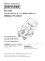
ZTS 7500
107.249210
Fits ZTS 7500 Model No.
107.27786
107.27788
107.27790
(42" Mower)
(44" Mower)
(50" Mower)
CAUTmON: Before using this product, read
the manuaWand follow all its Safety Rules
and Operating Instructions.
For answers to your questions about this
product, call:
1-800=659=5917
Sears Craftsman Help Line
5 am - 5 pm, blon - Sat
Note : La traduction frangaise du manueU de cet
operateur commence b,Rapage 19.
Nota: Una traducci6n en espa_oU de este ManuaU
del Operador puede encontrarse en la pAgina 37.
Sears, Roebuck and Co., Hoffman Estates, IL 60179 U.S.A.
Visit our Craftsman website: www.sears.com/craftsman
Service Mark of Sears Brands, LLC SM Trademark/TM@ Registered Trademark
1734238
Revision: 06
TP 199-4450-06-AT-C

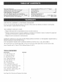
Warranty Statement ..................................................... 2
Safety RuJes & information for Bagger ..................... 5
Operating instructions for Bagger ............................. 6
initial Assembly & installation .................................... 7
44" & 50" Mode[ Assembly and installation ............ 11
Normal installation/Removal of 44" & 50" Bagger.14
42" Mode[ Assembly and installation ...................... 16
Normal installation/Removal of 42" Bagger ............ 20
French Manual ........................................................... 19
Spanish Manual ......................................................... 37
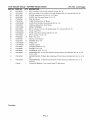
Repair Parts ......................................................... PTS-1
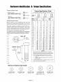
Hardware identification &
Torque Specifications ................... inside Back Cover
Service Telephone Numbers .................... Back Cover
ONE YEAR FULL WARRANTY on CRAFTSMAN 2-BIN BAGGER
For one (1) year from the date of purchase, if any parts of this product are defective in material or workmanship,
Sears w[[[ repair or replace them free of charge,
THIS WARRANTY DOES NOT COVER:
o Bagger cloth bags which are expendable and wear out with normal use,
Repairs necessary because of operator negligence, including but not limited to, failure to maintain the equipment
according to the instructions contained in the operator's manual
o Bagger if used for commercial or rental purposes,
WARRANTY SERVICE IS AVAILABLE BY RETURNING DEFECTIVE PARTS TO THE NEAREST SEARS PARTS &
REPAIR CENTER IN THE UNFED STATES,
FOR THE NEAREST SEARS PARTS & REPAIR CENTER LOCATION, CALL 1-800-4-MY-HOME ®,
This warranty gives you specific legal rights, and you may also have other rights which vary from state to state,
Sears, Roebuck and Co,, Dept, 817WA, Hoffman Estates, [L 60179
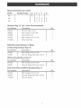
TOOLS REQUIRED
Description Quantity
7/16" Box Wrench, 6 Pt 1
1/2" Open-end Wrench 1
1/2" Box Wrench, 6 Pt 1
9/16" Open-end Wrench 1
9/16" Box Wrench, 6 Pt 1
3/8" Drive Ratchet 1
3/8" x 3" Extension Bar 1
7/16" x 3/8" Drive, Socket, 6 Pt 1
1/2" x 3/8" Drive, Socket, Deep, 6 Pt 1
9/16" x 3/8" Drive, Socket, 6 Pt 1
3/4" x 3/8" Drive, Socket, Deep, 6 Pt 1
#2 Phi[lips Screw Driver 1
See Page 55 for Wrench and Fastener Size Guide,

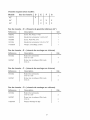
Required Hardware per mode_:
Mode_ Hardware Bag: D
42" X
44"
50"
E
X
X
F G
X X
X X
Hardware Bag "D" (42" Lower Chute Hardware}
Part Number
1928372
1960252
1933988
1931334
1734355A
Description
Nut, Hex, Keps, 1/4-20
Bolt, Carriage, 1/4-20 x 5/8"
Nut, Push Pal, 5/16
Bolt, Carriage, 5/16-18 x 7/8"
Plate, Latch, Rear
Qty
1
1
1
1
1
Baffle Mounting Hardware (3 Bags}
LH Mounting Hardware Bag "E"
Part Number Description Qty
_32 BoUt,Carriage, 5/16-18 x 5/8" 4
1927557 Nut, Hex, Fange, Wh z Lock, 5/16-18 4
RH Mounting Hardware Bag "F"
Part Number Description Qty
Boot Pivot P_ate and Mount Hardware Bag "G"
Part Number
1931332
1927557
1726578A
Description
BoUt,Carriage, 5/16-18 x 5/8"
Nut, Hex, FUange,Whiz Lock, 5/16-18
PUate,Rod Mount
Qty
2
2
1

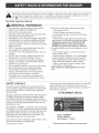
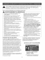
Readthesesafetyrubsandfollowthemclosely,Failuretoobeytheserubscouldresultinlossofcontrolof
unit,severepersonalinjuryordeathtoyou,orbystanders,ordamagetopropertyorequipment,Thetrian-
gb _ intextsignifiesimportantcautionsorwarningswhichmustbefollowed,
See Rider Operators Manua_
GENERAL WARNINGS
Know the unit's controb and how to stop qubkly,
READ THE OPERATOR'S MANUALS,
Read and obey all safety decals,
o Only allow responsibb aduRs, who are familiar with
the instructions, to operate the unit,
o Disengage the PTO, Shut off the engine and wait for
all moving parts to stop before attaching, adjusting,
or disconnecting any part of the collection system,
o Check the collection system to make sure it is bolted
tightly to the unit,
o DO NOT operate the unit without either the entire
grass bagger or the deflector in place,
o Turn off the PTO to disengage the blades when not
mowing,
o DO NOT mow in reverse, Always look down and
behind before and while travelling in reverse,
o DO NOT turn sharply when travelling alongside a
building or any object, Slow down before turning,
o DO NOT carry passengers,
o When collection system is removed from the mower
deck, the deflector must be properly installed,
o Grass bagger components are subject to wear,
damage, and deterioration, which could expose
moving parts or allow objects to be thrown,
Frequently check components and replace with
manufacturer's recommended parts, when neces-
sary,
If the mower stalls or the collector chute plugs:
1, Disengage the PTO;
2, Stop the engine and remove the key;
3, Set the parking brake, and wait for all moving
parts to stop,
4, Remove the foreign object or clear the chute
with a piece of wood before restarting the engine,
NEVER ptace hands into COLLECTOR OR
MOWER housing to cJear jammed objects.
MOWER may rotate when object is removed.
o For added stability and to prevent tipping or loss of
control:
a, Use reduced speed on uneven ground and
when turning corners,
b, Reduce loads on hillsides, it is recommended
that the collection system be kept only half full
when negotiating any slopes, Start mowing on
slopes when the collection system is empty,
c, Mow up and down the face of slopes; never
across the face of any slope,
Never operate on slopes greater than 17.8%
(105
SAFETY DECALS
This unit has been designed and manufactured to pro-
vide you with the safety and reliability you would expect
from an industry leader in outdoor power equipment
Although reading this manual and the safety instructions
it contains will provide you with the necessary basic
knowledge to operate this equipment safely and effec-
tively, we have placed several safety labels on the unit to
remind you of this important information while you are
operating your unit,
All DANGER, WARNING, CAUTION and instructional
messages on your rider, attachments and mower should
be carefully read and obeyed, Personal bodily injury can
result when these instructions are not followed, The
information is for your safety and it is important! The
safety decals below are on your product,
if any decals are lost or damaged, replace them at once,
See your local dealer for replacements,
TP 600-2562-01-AT-SMA
These labels are easily applied and will act as a constant
visual reminder to you, and others who may use the
equipment, to follow the safety instructions necessary for
safe, effective operation,
ATTACHMENT DECAL
DecaJ - WARNING
Thrown Objects
Part Number - 1732819
Read and obey all operation and warning decals.

BEFORE OPERATION
CHearthe Hawnof aHHsticks, stones, wire and other debris
which may be caught or thrown by the mower bHades,
Check grass condition, Hfwet, wait until Haterin the day,
Hfgrass is wet, the grass catcher is HkeHyto become
pHugged,
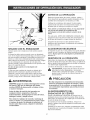
For efficient bagging, air circulation under the
mower deck, through the chute and into the bag is
very important.
For tMs reason, BEFORE YOU BEGHN MOWHNG you
shouHdmake certain the underside of the mower and
the underside of the catcher Hidare free from grass and
debris,
Make sure that there is a snug fit between mower deck,
blower housing, tubes, and hopper,
MOWING WiTH THE BAGGER
Always operate with throttle at fuil speed when mowing,
Grass should be cut often, but not too short, if grass is
too long or lush it may be necessary to keep ground
speed to a minimum or to cut only half the width of the
mower to prevent clogging, if grass is long, operate with
mower in high cutting position for first pass, cutting again
in a lower position on a second pass,
Do not open the cover with mower engaged.
Hfa Hargeamount of cut grass is spHHngout from under
deck, the tube may be pHuggedor the bags may be fuHH--
discontinue mowing, stop the rider, disengage the PTO,
shut off the engine and then empty the bagger or clear
the tube,
REQUIRED ACCESSORIES
A front-mounted weight of 32 Ibs, is required when using
this rear-mounted grass catcher, Never operate mower
on slopes greater than 10°.
AFTER OPERATION
Remove any debris from the the screen on the underside
of the hopper lid, Note: The lid screen can be partially
removed for easier cleaning and should be cleaned regu-
larly,
The discharge tubes shouHd be removed for cHeaning,
,_ WARNING: Hnspectthe grass bags for wear or
hoHedamage before and after each use, Debris
can fly through homesduring operation,
CAUTION
WARNING
ALWAYS shut off the unit. Disengage the PTO,
and allow all moving parts to stop BEFORE
disconnecting or clearing tube, or emptying
catcher.
Before leaving the operator's position for any
reason, engage the parking brake, disengage the
PTO, stop the engine and remove the key.
To reduce fire hazard, keep the engine, rider and
mower free of grass, [eaves and excess grease.
Do not stop or park rider over dry leaves, grass or
combustible materials.
Do not leave grass in bagger containers. Empty
containers after each use and before storing.
Failure to do so may resuIt in spontaneous
combustion which couJd deveIop into a fire.
STORING THE GRASS BAGGER
Clean the grass bagger thoroughHy using a mild deter-
gent (other products may damage the tube), Remove
any debris from the the screen on the underside of the
Hid,
If paint has been scratched on metal parts, touch up with
paint, or appHya thin fiHmof o1[to prevent corrosion,
Store in a dry area, Dry thoroughHy before storing for a
[ong period of time, AHwaysstore away from moisture,

NOTE: mnthis manual, 'left" and "right" are a_ways defined from
the standpoint of the operator position facing forward from seat.
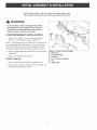
WARNING
To avoid serious injury, engage parking brake,
disengage PTO, stop engine, remove key and
disconnect spark plug(s) before attempting to
install, remove or work on the mower.
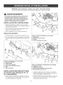
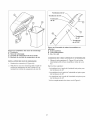
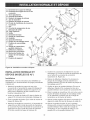
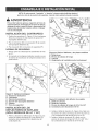
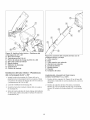
COUNTERWEIGHT iNSTALLATiON
1, Slide pins (A, Figure 1) on counterweight (B) into
slots (C) on front footrest support bracket (D),
NOTE: Counterweight pin and safety dip are attached to
the counterweight from the factory. The pin and safety
clip must be removed from the counterweight to attach
the counterweight to the front footrest support brackeL
2, Secure counterweight (B) with pin (E) to front footrest
support (D),
3, Secure pin (E) with safety clip (F),
SAFETY RULES
1, Never operate mower on slopes greater than 10°,
2, Front counter weight is required when ever using rear
mounted grass collection system,
Figure !. lnstalt Counter Weight
A. SJide Pins
B. Counter Weight
C. Pin SJots
D. Front Footrest Support
E. Pin
F. Safety Ctip

\
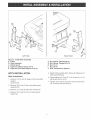
Left View Back View
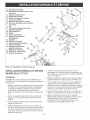
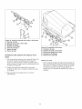
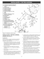
Figure 2. Install Hitch Assembly
A. Frame
B. Hitch Assembly
C. Debris Guard
D. Capecrew, Debris Guard, 3/8-18
E. Capscrew, Seat Deck Support, 5/18-18
F. Nut, Nylock, Ftanged 3/'8-18
G. Nut, Nylock, Ftanged 5/18-16
H. Nut, !/2-!3
I. Nut, 3/8-!6
J. Rear Transmission Support
HITCH iNSTALLATiON
Hitch mnstaHation
1, Remove 5/16=16 nut (G, Figure 2) from seat deck
support
capscrew (E),
2, Remove 3/8-16 nut (F) from rear debris guard
capscrew (D),
3, Remove 1/2=13 nut (H) from rear of frame (A),
4, Remove 3/8-16 nut (I) from rear transmission
support (J),
5,
6,
7,
Attach hitch assembly (B) to frame (A) sliding rear of
hitch flush with frame,
Finger tighten 3/8=16 nut (F), 5/16=16 nut (G), 1/2=13
nut (H) and 3/8=16 nut (I),
Tighten 3/8-16 nut (F) and 5/16=16 nut (G) first, then
1/2=13 nut (H) and 3/8-16 nut (I),

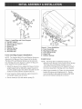
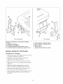
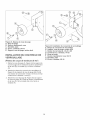
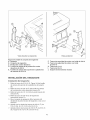
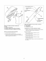
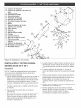
Figure3. install Bag and Cover Support
A. Upright Support
B. Bag and Cover Support
C. Support Mount
D. Mount Pin
E. Retainer Spring
F. Shoulder Rest
G. Shoulder Bolt
Cover and Bag Support hstaHation
NOTE." The Support Mount Pin and Retainer Spring are
attached to the Bag and Cover Support at the factory.
The Mount Pin and Retainer Spring must be removed
from the Bag and Cover Support to attach the Bag and
Cover Support to the Upright Support.
t, Attach the bag and cover support (B, Figure 3) to the
upright support (A) by sliding the support mount (C)
over the upright support (A) until the shoulder rest (F)
makes full contact with the shoulder bolts (G),
2, insert mount pin (D) through the support mount (C)
and upright support (A) as shown,
3, Secure mount pin (D) with retainer spring (E),
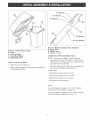
Figure 4. Cover installation
A. Cover AeeemMy
B. Bag Support Bracket
C. Cover Hinge Pivots
D. Hinge Pine
E. Retainer Springs
hstaH cover
NOTE: The Hinge Pins and Retainer Springs are
attached to the Bag and Cover Support at the factory.
The Hinge Pins and Retainer Springs must be
removed from the Bag and Cover Support to attach
the Cover Assembly to the Bag and Cover Support.
1. Attach cover assembly (A, Figure 4) to bag support
bracket (B) using cover hinge pivots (C). Secure
cover assembly to bag support bracket using hinge
pins (D) and retainer springs (E) as shown.

Figure5. install Collector Bags
A. Cover
B. Collector Bags
C. Grass Bag Hanger
D. Bag Hanger Post
iNSTALL COLLECTOR BAGS
1. Raise the cover (A, Figure 5).
2. Attach collector bags (B) using grass bag hanger (C)
to bag hanger post (D).
44" Mowers
50"
42" Mowers
\
-%
42" Mowers
44"/50" Mowers
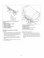
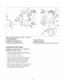
Figure 6. Middle and Upper Tube Assembly
A. Upper Tube
B. Middle Tube
C. Screw, 1/4 x 3/4
CONNECTING UPPER AND M_DDLETUBE
NOTE: The Upper and Middle Tube are shipped
assembled for use on 50" mowers. If yeur model
differs from this configuration you wifl need to make
adjustments in the assembly.
1. SHdethe upper tube (A, Figure 6) over middUetube
(B) and secure together using screw (C).
Unupper tube:
: Third hoUefrom end is for 42" mowers
- Fourth hoUefrom end is for 50" mowers
- Fifth hoUefrom end is for 44" mowers,
See Figure 8 for hoUeUocations,
NOTE:
If you are installing a bagger on 44" or 50" mowers
continue with the installation on page 10.
If you are installing a bagger on a 42" mower continue
with the installation beginning on page 14.

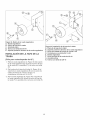
Figure 7. Remove Baffle and Hardware
A. BaffJee
B. Carriage Bolts
C. Nuts
D. Mower Deck Housing
iNSTALL BLOWOUT BAFFLES
1, Remove and discard existing baffles (A, Figure 7)
carriage bouts (B) and nuts (C) from mower deck
housing (D),
2, UnstaHLH baffle (A, Figure 8), and secure with
5/16-18 x 5/8 carriage bouts (C) and 5/16-18 Whiz
Lock nuts (D),
3, UnstaHRH baffle (B), and secure with 5/16-18 x 5/8
carriage bouts (C) and 5/16-18 Whiz Lock nuts (E),
Figure 8. Blowout Baffle Installation
A. Baffle, LH
B. Baffle, RH
C. Carriage Bolts, 5/16-18 x 5/8
D. Nut, Whiz Lock, 5/18-18
10

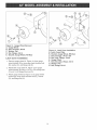
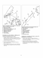
Figure9. install Lower Chute
A. Lower Chute
B. Mounting Plate
C. Locknuts, 5/16-18
D. Carriage Bolt, 5/16-18 x 5t'8
E. Lower Chute Rod
F. Rubber Strap
G. Discharge Deflector
H. Locknut
I. Mounting Hole
Lower Chute mnstaHation
1, install mounting pUate(A, Figure 9) to mower deck as
shown, Secure with 5/16-18 x 5/8 carriage bouts (C)
and 5/16-18 bcknuts (B),
2, Lift discharge deflector (F),
3, insert bwer chute rod (D) into mounting pUate(A),
4, Pull rubber strap (E) bebw discharge deflector, and
secure by pUacinghob (H) over bcknut (G),
////_
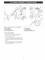
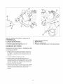
Figure 10. Connecting Tube Assembly to Lower
Chute and Cover
A. Upper Tube
B. Cover
C. Ridge, Upper Tube
D. Ridge Cutout
E. Lower Chute
F. Strap, Rubber
G. Pin
H. Tube Assembly
CONNECTING TUBE ASSEMBLY TO LOWER CHUTE AND
COVER
1, Slide the upper tube (A, Figure 10) into cover (B)
aligning ridge (C) with cutout (D) as shown,
2, Slide tube assembly(H) over lower chute (E), Secure
tube assembly (H) to lower chute (E) using strap (F)
and pin (G),
11

%
/t
/
/
/
/
/
/
/
/
//
/
/
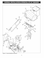
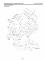
Figure 11. NormaJ installation & RemovaJ
12

Figure11.continued...
A. HitchAssembJy
B. BagandCoverSupportAssembty
C. ShoulderRest
D. MountPin
E. RetainerSpring
F. HingePine
G.RetainerSprings
H. CoverhingePivots
I. Cover
J. Bag
K. Bag Hanger
L. Ridge Cutout
installation
NOTE." See previous pages for more detailed installation
and operation instructions if necessary.
1. Attach bag and cover support assemMy
(B, Figure 11) to hitch support assemMy (A) by
sliding the support mount (X) over the upright support
until the support mount (X) makes full contact with
the shouUder bouts (C).
2. Unsertmount pin (D) through the support mount (X)
and upright support (A) as shown.
3. Secure mount pin (D) with retainer spring (E).
4. Attach cover assembly (I) to bag support bracket (B)
using cover hinge pivots (H). Secure cover assembly
to bag support bracket using hinge pins (F) and
retainer springs (E).
5. Raise the cover (I), attach collector bags (J) using
grass bag hanger (K) to bag hanger post
(D, Figure 7).
6. Lift discharge deflector (V) up and insert lower chute
rod (S) into mounting plate (T).
7. Pull rubber strap (U) below discharge deflector (U)
and secure lower chute (R) to mower deck by placing
hole in rubber strap (U) (hole closest to lower chute)
over Iocknut mount (W).
8. Slide upper tube (M) into cover (I) aligning ridge (N)
with ridge cutout (L).
9. Slide tube assembly (0) over lower chute (R)
securing tube assembly (0) to lower chute (R) using
rubber strap (P) on tube assembly (0) to pin (Q) on
lower chute (R).
M. Upper Tube
N. Ridge
O. Tube AssemMy
P. Rubber Strap, Middte
O. Pin
R. Lower Chute
S. Lower Chute Rod
T. Mounting PJate
U. Rubber Strap, Lower Chute
V. Discharge Deflector
W. Locknut Mount
X. Support Mount
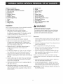
WARNING
OPERATION WITHOUT BAGGER
For operation without bagger, the mower discharge
deflector MUST be properly installed in the DOWN
position and retained by the spring latch,
Remova_
1. Disconnect rubber strap (P, Figure 11) from pin (Q)
then remove tube assembly (0) from lower chute (R)
and from cover (I).
2. Lift cover (I) and remove bags (J) from bag and cover
support assembly (B).
NOTE: Support the cover during the next step.
3. Remove cover (I) by disconnecting retainer springs
(G), then remove both hinge pins (F).
4. Remove bag and cover support assembly (B) from
hitch assembly (A) by removing retainer spring (E),
then removing mount pin (D).
NOTE: To prevent loss of pins and retainer springs
re-attach them to the cover, and bag and cover
support assembly.
5. Remove lower chute (R) by lifting up discharge
deflector (V), and removing lower chute rod (S) from
mounting plate (T).
IMPORTANT: See that discharge deflector (R) returns to
the DOWN position.
13

\
Figure 12. Guage Wheet RemovaJ
A. Guage Wheel
B. BoJt, Shoulder, Wheel
C. Washer, Flat
D. Nut, Ftange, 3/8-!6
E. Bracket, Guage Wheel, RH-Rear
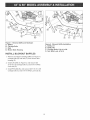
Latch Cover hstaHation
1, Remove guage wheel (A, Figure 12) from guage
wheel bracket (E) by removing wheel shoulder bolt
(B), washer (C), and flange nut (D),
2, Attach latch cover plate (A, Figure 13) to guage
wheel bracket (B) using a 1/4-20 x 5/8 carriage bolt
(C) and 1/4-20 flanged lock nut (D),
3, Attach guage wheel (E, Figure 13) to guage wheel
bracket (B) using wheel shoulder bolt (F), washer
(G), and flange nut (H),
Figure 13. Latch Cover installation
A. Latch Cover Plate
B. Bracket, Guage Wheel, RH-Rear
C. Bolt, Carriage, 1/4-20 x 5/8
D. Nut, Lock, Flange, 1/4-20
B. Guage Whee!
F. Bolt, Shoulder, Wheel, 3/8-16
G. Washer, Flat
H. Nut, Flange, 3/8-16
14

®
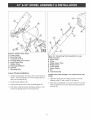
Figure 14. install Lower Tube - 42" Mower Deck
A. Lower Chute
B. Front Latch Ptate
C. Front Latch Mount
D. Bolt, Carriage, 5/16 × 7t'8
Lower Tube mnstaHation
1, Install 5/16 x 7/8 carriage bolt (D, Figure 14) with
5/16 push nut (E) to mower deck as shown,
2, Lift discharge deflector (G),
3, Insert front latch plate (B) into front latch plate mount
(C), Swing lower chute into place below discharge
deflector (G) placing hole in lower chute over carriage
belt (D),
4, Stretch rubber strap (F) down to the rear latch plate
mount bolt (H) attaching the first hole in the rubber
strap over the mount bolt,
E. Nut, Push, 5/'16
F. Strap, Rubber
G. Discharge Deflector
H. Bolt, Rear Latch Plate Mount
15

@
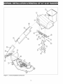
Figure 15. NotmaJ installation & RemovaJ
16

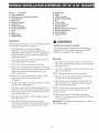
Figure15 continued...
A. HitchSupportAssembly
B. BagandCoverSupportAeeembty
C. ShoulderBolt
D. Mount Pin
E. Retainer Spring
F. Hinge Pin
G. Retainer Spring
H. Cover Hinge Pivots
I. Cover
J. Bag
K. Bag Hanger
L. Ridge Cutout
mnstaHation
NOTE." See previous pages for more detailed installation
and operation instructions if necessary.
1. Attach bag and cover support assembUy
(B, Figure 15) to hitch support assemMy (A)
by sliding the support mount (Y) into pUaceuntil full
contact is made with the shouUder bouts (C).
2. insert mount pin (D) through support mount (Y) and
upright of hitch assemMy (A).
3. Secure mount pin (D) with retainer spring (E).
4. Attach cover assembUy (U)to bag support assembly
(B) using cover hinges pivots (H). Secure cover
assembly (I) to bag support bracket (B) using hinge
pins (F) and retainer springs (G).
5. Raise the cover (I), and attach collector bags (J)
using grass bag hanger (K) to hanger post
(D, Figure 7).
6. Lift discharge deflector (V, Figure 15) up, and insert
front latch plate (S) into front latch plate mount (T).
7. Swing lower chute (R) into place below discharge
deflector (V) placing hob in lower chute over carriage
bolt (W).
8. Stretch rubber strap (U) down to the rear latch plate
mount bolt (X) attaching the first hob in the rubber
strap over the mount bolt.
9. Slide upper tube (M) into cover (I) aligning ridge (N)
with ridge cutout (L).
10. Slide tube assembly (0) over lower chute (R)
securing tube assembly (0) to lower chute (R) using
rubber strap (P) on tube assembly (0) to pin (Q) on
lower chute (R).
M. Upper Tube
N. Ridge
O. Tube AeeemMy
P. Rubber Strap
Q. Pin
R. Lower Chute
S. Front Latch Plate
T. Front Latch [Vlount
U. Rubber Strap, Lower Chute
V. Discharge Deflector
W. Carriage BoJt
X. Rear Latch Plate IVlount Bolt
Y. Support Mount
WARNING
OPERATION WITHOUT BAGGER
For operation without bagger, the mower discharge
deflector blUST be properly installed in the DOWN
position and retained by the spring latch.
Remova_
1. Unhook rubber strap (P, Figure 15) from pin (Q), then
remove tube assembly (0) from lower chute (R) and
from cover (I).
2. Lift cover (I) and remove bags (J) from bag and cover
support assembly (B).
NOTE: Support the cover during the next step.
3. Remove cover (I) by disconnecting retainer springs
(G), then remove both hinge pins (F).
4. Remove bag and cover support assembly (B) from
hitch assembly (A) by removing retainer spring (E),
then removing mount pin (D).
NOTE: To prevent loss of pins and retainer springs
re-attach them to the cover, and bag and cover support
assembly.
5. Disconnect lower chute rubber strap (U, Figure 15)
from rear latch plate mount bolt (X).
6. Lift up discharge deflector (V, Figure 15); remove
lower chute (R) from carriage bolt (W), then remove
front latch latch plate (S) from front latch mount (T).
IMPORTANT: See that discharge deflector (R) returns to
the DOWN position.
17

18

ZTS 7500
2 CO
107.249210
Pour ZTS 7500 ModUle N°
107.27786
107.27788
107.27790
(Tondeuse de 42")
(Tondeuse de 44")
(Tondeuse de 50")
ATTENTION : Avant d'ufiWiser ce produit, life
le manuel et suivre toutes ses consignes de
secudt6 et ses instructions de
foncfionnement.
Pour toute r@onse A des questions sur ce
produit, appelez le :
1°800-659-5917
Sears Craftsman Help Line
de 5 h 00 a.17 h 00, du Uundiau samedi
Sears, Roebuck and Co., Hoffman Estates, IL 60179 U.S.A.
ConsuUter Uesite Web de Craftsman : www, sears,com/craftsman
Marque de service des Marques Sears, LLC SM Marque/TM® Marque depos6e

Enonc_degarantie...................................................20
Consigneedee_curit_et lnformatione
reJativee _ J'eneacheuee .......................................... 22
instructions de fonctionnement pout
l'eneacbeuee ............................................................. 23
Montage initiaJ et installation ................................... 24
installation normaJe et D_poee ................................ 32
Pi_cee de reparation ........................................... PTS-1
identification de vieeer[e et
specifications de couple ...Troiei_me de couvertute
Nurneroe de t_J_phone
de service ....................................... Couverture ard_re
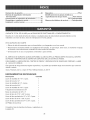
PLEINE GARANTE D'UN AN sur L'ENSACHEUSE A 2 COMPARTIMENTS CRAFTSMAN
Pendant un (1) an & compter de la date d'achat, si toute pi_,ce de ce produit pr6sente un vice de mat6riau ou de
fabrication, Sears la r6parera ou la remplacera gratuitement.
LA PR¢:SENTE GARANTE NE COUVRE PAS CE QUI SUIT :
o Les sacs en tissu d'ensacheuse qui sont extensibles et s'usent dans des conditions normales d'utilisation.
Les reparations n6cessaires en raison de la n6,gligence de I'utilisateur, y compris mais sans s'y limiter, le manque
d'entretien de 1'6quipement conform6,ment aux instructions figurant dans le manuel d'utilisation.
o L'ensacheuse en cas d'utilisation & des fins commerciales ou de location.
TOUTE R¢:PARATION SOUS GARANTE EST DISPONIBLE EN RETOURNANT LES PIC:CES D¢:FECTUEUSES
AU CENTRE DE PIC:CES ET DE R¢:PARATION SEARS LE PLUS PROCHE AUX €:TATS-UNIS.
POUR CONNAUTRE L'EMPLACEMENT DU ,, SEARS PARTS & REPAIR CENTER >_LE PLUS PROCHE, APPELEZ
LE 1-800-4-MY-HOME ®.
La pr6sente garantie vous offre des droits 16gaux sp6cifiques et il se peut que vous ayez d'autres droits qui varient
d'une juridiction & une autre.
Sears, Roebuck and Co., Dept. 817WA, Hoffman Estates, IL 60179 U.S.A.
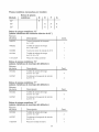
OUTJLS F{EQUJS
Description Quantit_
CI6 polygonale 7/16", 6 Pt 1
CI6 a fourche 1/2" 1
CI6 polygonale 1/2", 6 Pt 1
CI6 a.fourche 9/16" 1
CI6 polygonale 9/16", 6 Pt 1
CI6 a.diquet 3/8" 1
Rallonge 3/8" x 3" 1
CI6 a douilles 7/16" x 3/8", 6 Pt 1
CI6 & douilles 1/2" x 3/8", Iongue, 6 Pt 1
CI6 a.douilles 9/16" x 3/8", 6 Pt 1
CI6 a.douilles 3/4" x 3/8", Iongue, 6 Pt 1
#2 Phillips Screw Driver 1
Voir Guide de tailles de cl6s et de fixations en page 55.
2O
La page est en cours de chargement...
La page est en cours de chargement...
La page est en cours de chargement...
La page est en cours de chargement...
La page est en cours de chargement...
La page est en cours de chargement...
La page est en cours de chargement...
La page est en cours de chargement...
La page est en cours de chargement...
La page est en cours de chargement...
La page est en cours de chargement...
La page est en cours de chargement...
La page est en cours de chargement...
La page est en cours de chargement...
La page est en cours de chargement...
La page est en cours de chargement...
La page est en cours de chargement...
La page est en cours de chargement...
La page est en cours de chargement...
La page est en cours de chargement...
La page est en cours de chargement...
La page est en cours de chargement...
La page est en cours de chargement...
La page est en cours de chargement...
La page est en cours de chargement...
La page est en cours de chargement...
La page est en cours de chargement...
La page est en cours de chargement...
La page est en cours de chargement...
La page est en cours de chargement...
La page est en cours de chargement...
La page est en cours de chargement...
La page est en cours de chargement...
La page est en cours de chargement...
La page est en cours de chargement...
La page est en cours de chargement...
La page est en cours de chargement...
La page est en cours de chargement...
La page est en cours de chargement...
La page est en cours de chargement...
-
 1
1
-
 2
2
-
 3
3
-
 4
4
-
 5
5
-
 6
6
-
 7
7
-
 8
8
-
 9
9
-
 10
10
-
 11
11
-
 12
12
-
 13
13
-
 14
14
-
 15
15
-
 16
16
-
 17
17
-
 18
18
-
 19
19
-
 20
20
-
 21
21
-
 22
22
-
 23
23
-
 24
24
-
 25
25
-
 26
26
-
 27
27
-
 28
28
-
 29
29
-
 30
30
-
 31
31
-
 32
32
-
 33
33
-
 34
34
-
 35
35
-
 36
36
-
 37
37
-
 38
38
-
 39
39
-
 40
40
-
 41
41
-
 42
42
-
 43
43
-
 44
44
-
 45
45
-
 46
46
-
 47
47
-
 48
48
-
 49
49
-
 50
50
-
 51
51
-
 52
52
-
 53
53
-
 54
54
-
 55
55
-
 56
56
-
 57
57
-
 58
58
-
 59
59
-
 60
60


Craftsman 107249210 Le manuel du propriétaire
- Catégorie
- Tondeuses à gazon
- Taper
- Le manuel du propriétaire
dans d''autres langues
Documents connexes
Autres documents
-
Simplicity CATCHER KIT, TWIN BAG, EUROPEAN REAR ENGINE RIDER Manuel utilisateur
-
Toro 42in Bagger, eTimecutter Riding Mower Manuel utilisateur
-
-
Snapper 1692714 Manuel utilisateur
-
-
Toro E-Z Vac Complete Twin Bagger, TimeCutter HD Riding Mower Manuel utilisateur
-
-
-
Cub Cadet 19A70054100 Manuel utilisateur
-
MTD OEM-190-182A Manuel utilisateur