Toro 20493 Manuel utilisateur
- Catégorie
- Tondeuses à gazon
- Taper
- Manuel utilisateur

Operator’s Manual
Manuel de L’Utilisateur
Manual del Operador
FORM NO. 3319–663
SR-21P Super Recycler
SR-21S Super Recycler
SR-21SE Super Recycler
Walk-behind Power Mower
Model No. 20493, 20494, 20495 — 8900001 & Up
SR-21P Super Recycler
SR-21S Super Recycler
SR-21SE Super Recycler
Tondeuse motorisée à guidage arrière
Modèle No. 20493, 20494, 20495 — 8900001 et suivants
SR-21P Super Recycler
SR-21S Super Recycler
SR-21SE Super Recycler
Cortadora de césped motorizada empujada por
el usuario
Modelos N. 20493, 20494, 20495 — 8900001 y siguientes

The engine exhaust from this product
contains chemicals known to the State of
California to cause cancer, birth defects,
or other reproductive harm.
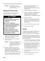
WARNING:
Les gaz d’échappement du moteur de ce
produit contiennent des produits
chimiques reconnus dans l’état de
Californie comme cancérigènes,
responsables de malformations
congénitales, ou comme nocifs à l’égard
des fonctions de la reproduction.
AVERTISSEMENT:
El escape del motor de esta herramienta
contiene productos químicos que según
la información del Estado de California
producen cáncer, defectos congénitos u
otros riesgos reproductivos.
ADVERTENCIA:

EThe Toro Company – 1997
Printed in USA
All Rights Reserved
i
Figures — Figuras
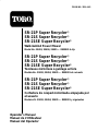
1778
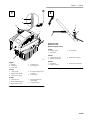
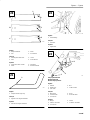
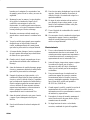
Self-propelled models
Modèle autotracté
Modelo autopropulsado
English
1. Model and serial number decal
Français
1. Décalcomanie de numéros de modèle et de série
Español
1. Calcomanía con los números de modelo y serie
1064
Hand push models
Modèle non tracté
Modelo de empuje manual
English
1. Model and serial number decal
Français
1. Décalcomanie de numéros de modèle et de série
Español
1. Calcomanía con los números de modelo y serie
311
English
1. Right handle knob 2. Left handle knob
Français
1. Bouton de droite 2. Bouton de gauche
Español
1. Perilla derecha de la
manija
2. Perilla izquierda de la
manija
1
2
3

Figures — Figuras
ii
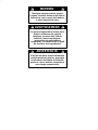
311
1
3
4
5
2
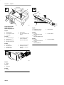
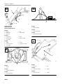
English
1. Cable tie (self-propelled
model only)
2. Cable tie (hand push
model only)
3. Handle latch
4. Handle stud
5. Control cable
Français
1. Attache de câble (modèle
autotracté uniquement)
2. Attache de câble (modèle
non tracté uniquement)
3. Patte de verrouillage
4. Goujon
5. Câble de commande
Español
1. Abrazadera para cables
(modelo autopropulsado
solamente)
2. Abrazadera para cables
(modelo de empuje
manual solamente)
3. Pestillo de la manija
4. Perno
5. Cable de control
m-1690
2
1
English
1. Rope guide 2. Starter rope
Français
1. Guide-câble 2. Câble de démarreur
Español
1. Guía del cable 2. Cable del arrancador
3
1
2
English
1. Wire harness
2. Battery pigtail
3. Battery case
Français
1. Faisceau de câblage
2. Cordon de batterie
3. Boîtier de batterie
Español
1. Arnés de cable
2. Cable de bateriá
3. Caso de bateriá
4 5
6

Figures — Figuras
iii
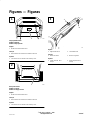
1626
3
2
1
4
5
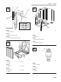
English
1. Dipstick
2. ADD mark
3. FULL mark
4. Fuel tank cap
5. Spark plug wire
Français
1. Jauge d’huile
2. Repère ADD (ajouter)
3. Repère FULL (plein)
4. Bouchon du réservoir de
carburant
5. Fil de bougie
Español
1. Varilla de nivel
2. Marca “ADD” (agregar)
3. Marca “FULL” (lleno)
4. Tapa del depósito de
combustible
5. Cable de la bujía
1
2
3
Hand push models
Modèle non tracté
Modelo de empuje manual
English
1. Throttle control
2. Control bar
3. Recoil starter
Français
1. Commande des gaz
2. Barre de commande
3. Démarreur de rappel
Español
1. Acelerador
2. Barra de control
3. Arrancador recuperador
7 8

Figures — Figuras
iv
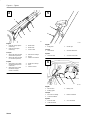
1802
2
1
3
4
5
Self-propelled models
Modèle autotracté
Modelo autopropulsado
English
1. Throttle control
2. Ground speed control
3. Control bar
4. Recoil starter
5. Key switch (electric start
model)
Français
1. Commande des gaz
2. Vitesse au sol
3. Barre de commande
4. Démarreur de rappel
5. Commutateur a clé de
contact (modèles à
démarreur électrique)
Español
1. Acelerador
2. Del sistema de
autoimpulsión
3. Barra de control
4. Arrancador recuperador
5. Interruptor con llave
(modelo con arranque
elétrico)
1344
1
English
1. Primer
Français
1. Amorceur
Español
1. Cebador
360
1
2
3
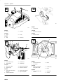
English
1. RUN/DRIVE position
2. RUN/SHIFT position
3. STOP position
Français
1. Position
MARCHE/TRACTION
2. Position
MARCHE/EMBRAYAGE
3. Position ARRET
Español
1. Posición
AVANCE/AUTOMATICO
2. Posición
AVANCE/MANUAL
3. Posición PARADA
9
10
11

Figures — Figuras
v
ABDEC
A = 1” (25 mm)
B = 1-1/2” (38 mm)
C = 2” (51 mm)
D = 2-1/2” (64 mm)
E = 3” (76 mm)
788
English
1. Height-of-cut lever
Français
1. Levier de hauteur de coupe
Español
1. Palanca de ajuste de altura de corte
1003
1
2
3
English
1. Air filter
2. Screw
3. Cover
Français
1. Filtre à air
2. Vis
3. Couvercle
Español
1. Filtro de aire
2. Tornillo
3. Cubierta
1782
English
1. Oil fill tube
Français
1. Tube de remplissage d’huile
Español
1. Tubo de llenado del aceite
986
English
1. .030 in. (.76 mm)
Français
1. 0,076 mm
Español
1. 0,076 mm
12
13
14
15

Figures — Figuras
vi
1709
English
1. Cover 2. Screw (2)
Français
1. Capot 2. Vis (2)
Español
1. Tapa 2. Tornillo (2)
1710
3
4
English
1. Cable clamp screw
2. Throttle cable
3. Throttle lever
4. Throttle stop
Français
1. Vis du serre-câble
2. Câble des gaz
3. Manette d’accélérateur
4. Butée d’accélérateur
Español
1. Tornillo de la abrazadera
del cable
2. Cable del acelerador
3. Palanca del regulador
4. Tope del regulador
402
English
1. Control knob
Français
1. Bouton de commande
Español
1. Botón de mando
757
2
1
3
English
1. Bolt and lockwasher
2. Accelerator
3. Blade
Français
1. Boulon et rondelle de
blocage de la lame
2. Accélérateur
3. Lame
Español
1. Perno y arandela de la
cuchilla
2. Acelerador
3. Cuchilla
16
17
18
19

Figures — Figuras
vii
1712
A
B
C
1
2
2
2
3
4
English
1. Flat part of blade
2. Sail
3. Wear
4. Slot formed
Français
1. Section plane de la lame
2. Pale
3. Usure
4. Fente formee
Español
1. Parte plana de la cuchilla
2. Aleta
3. Desgaste
4. Ranura formada
153
1
English
1. Sharpen at this angle only
Français
1. Aiguisez à cet angle seulement
Español
1. Afile en este angulo solament
276
1
English
1. Grease fitting
Français
1. Graisseur
Español
1. Engrasador
777
1
2
3
4
5
Self-propelled models
Modèle autotracté
Modelo autopropulsado
English
1. Handle
2. Brake lever
3. 1/8”–3/16”
4. Nut
5. Cable conduit
Français
1. Mancheron
2. Levier de frein
3. 3,2–4,8 mm
4. Ecrou
5. Gaîne du câble
Español
1. Manija
2. Palanca del freno
3. 3,2–4,8 mm
4. Tuerca
5. Conducto del cable
20
21
22
23

Figures — Figuras
viii
251
1
2
3
4
5
Hand push models
Modèle non tracté
Modelo de empuje manual
English
1. Handle
2. Brake lever
3. 1/8”–3/16”
4. Nut
5. Cable conduit
Français
1. Mancheron
2. Levier de frein
3. 3,2–4,8 mm
4. Ecrou
5. Gaîne du câble
Español
1. Manija
2. Palanca del freno
3. 3,2–4,8 mm
4. Tuerca
5. Conducto del cable
7961
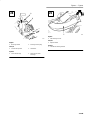
English
1. Kickers
Français
1. Plaques de déflection
Español
1. Placas deflectoras
10931
English
1. Right rear wheel
Français
1. Roue arrière droite
Español
1. Rueda trasera derecha
281
1
2
English
1. Belt cover 2. Bolt
Français
1. Garde de la courroie 2. Boulon
Español
1. Tapa de la correa 2. Tornillo
24
25
26
27

Figures — Figuras
ix
1915
2
1
English
1. Discharge tunnel 2. Discharge tunnel plug
Français
1. Conduit de l’éjecteur 2. Obturateur
Español
1. Canal de descarga 2. Tapón del canal de
descarga
2047
English
1. Side discharge chute
Français
1. Ejecteur latéral
Español
1. Canaleta de descarga lateral
28 29

EN–1
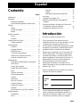
Contents
Page
Introduction 1. . . . . . . . . . . . . . . . . . . . . . . . . . . .
Safety 2. . . . . . . . . . . . . . . . . . . . . . . . . . . . . . . . .
Safe Operating Practices 2. . . . . . . . . . . . . .
Safety and Instruction Decals 5. . . . . . . . . .
Assembly 6. . . . . . . . . . . . . . . . . . . . . . . . . . . . . .
Handle 6. . . . . . . . . . . . . . . . . . . . . . . . . . . .
Starter Rope 6. . . . . . . . . . . . . . . . . . . . . . . .
Battery 6. . . . . . . . . . . . . . . . . . . . . . . . . . . .
Before Starting 6. . . . . . . . . . . . . . . . . . . . . . . . . .
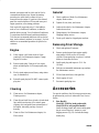
Oil 6. . . . . . . . . . . . . . . . . . . . . . . . . . . . . . . .
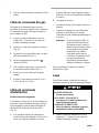
Gasoline 7. . . . . . . . . . . . . . . . . . . . . . . . . . .
Recycling Tips 8. . . . . . . . . . . . . . . . . . . . . . . . . .
General Tips 8. . . . . . . . . . . . . . . . . . . . . . . .
Operation 9. . . . . . . . . . . . . . . . . . . . . . . . . . . . . .
Controls 9. . . . . . . . . . . . . . . . . . . . . . . . . . .
Starting Engine 9. . . . . . . . . . . . . . . . . . . . . .
Stopping Engine 9. . . . . . . . . . . . . . . . . . . . .
Self-propelled Drive 9. . . . . . . . . . . . . . . . . .
Pulling Mower Rearward 10. . . . . . . . . . . . . .
Adjusting Cutting Height 10. . . . . . . . . . . . . .
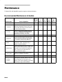
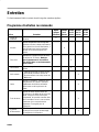
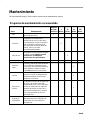
Maintenance 11. . . . . . . . . . . . . . . . . . . . . . . . . . . .
Recommended Maintenance Schedule 11. . .
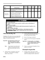
Air Filter 12. . . . . . . . . . . . . . . . . . . . . . . . . . .
Drain Gasoline 12. . . . . . . . . . . . . . . . . . . . . .
Change Engine Oil 12. . . . . . . . . . . . . . . . . . .
Spark Plug 13. . . . . . . . . . . . . . . . . . . . . . . . .
Throttle Cable 13. . . . . . . . . . . . . . . . . . . . . .
Self-propelled Cable 13. . . . . . . . . . . . . . . . .
Blade 14. . . . . . . . . . . . . . . . . . . . . . . . . . . . .
Lubrication 15. . . . . . . . . . . . . . . . . . . . . . . . .
Blade Brake 15. . . . . . . . . . . . . . . . . . . . . . . .
Charging Battery 15. . . . . . . . . . . . . . . . . . . .
Disposing of Battery 16. . . . . . . . . . . . . . . . .
Cleaning 16. . . . . . . . . . . . . . . . . . . . . . . . . . .
Underside of Mower Housing 16. . . . . . . . . .
Storage 17. . . . . . . . . . . . . . . . . . . . . . . . . . . . . . . .
Fuel 17. . . . . . . . . . . . . . . . . . . . . . . . . . . . . . .
Engine 18. . . . . . . . . . . . . . . . . . . . . . . . . . . .
Cleaning 18. . . . . . . . . . . . . . . . . . . . . . . . . . .
General 18. . . . . . . . . . . . . . . . . . . . . . . . . . . .
Removing From Storage 18. . . . . . . . . . . . . .
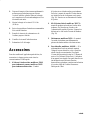
Accessories 18. . . . . . . . . . . . . . . . . . . . . . . . . . . .
The Toro Starting Guarantee 20. . . . . . . . . . . . . . .
Guaranteed To Start Maintenance Record 22. . . . .
Federal and California Emission Control Warranty
Statement 23. . . . . . . . . . . . . . . . . . . . . . . . . . . . .
The Toro Performance Warranty 26. . . . . . . . . . . .
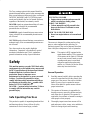
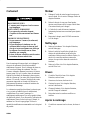
Introduction
Thank you for purchasing a Toro product.
All of us at Toro want you to be completely satisfied
with your new product, so feel free to contact your
local Authorized Service Dealer for help with service,
genuine Toro parts, or other information you may
require.
Whenever you contact your Authorized Service
Dealer or the factory, always know the model and
serial numbers of your product. These numbers will
help the Service Dealer or Service Representative
provide exact information about your specific
product. You will find the model and serial number
decal located in a unique place on the product
(Fig. 1 & 2).
For your convenience, write the product model and
serial numbers in the space below.
Model No.
Serial No.
Read this manual carefully to learn how to operate
and maintain your product correctly. Reading this
manual will help you and others avoid personal injury
and damage to the product. Although Toro designs,
produces and markets safe, state-of-the-art products,
you are responsible for using the product properly
and safely. You are also responsible for training
persons who you allow to use the product about safe
operation.

EN–2
The Toro warning system in this manual identifies
potential hazards and has special safety messages that
help you and others avoid personal injury, even death.
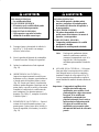
DANGER, WARNING and CAUTION are signal
words used to identify the level of hazard. However,
regardless of the hazard, be extremely careful.
DANGER signals an extreme hazard that will cause
serious injury or death if the recommended
precautions are not followed.
WARNING signals a hazard that may cause serious
injury or death if the recommended precautions are
not followed.
CAUTION signals a hazard that may cause minor or
moderate injury if the recommended precautions are
not followed.
Two other words are also used to highlight
information. “Important” calls attention to special
mechanical information and “Note” emphasizes
general information worthy of special attention.
Safety
This machine meets or exceeds CPSC blade safety
requirements for walk–behind rotary mowers and
the B71.1 specifications of the American National
Standards Institute, in effect at time of
production. However, improper use or
maintenance by the operator or owner can result
in injury. To reduce the potential for injury,
comply with these safety instructions and always
pay attention to the safety alert
symbol which
means CAUTION, WARNING or
DANGER—“personal safety instruction.” Failure
to comply with the instruction may result in
personal injury.
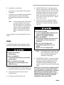
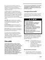
Safe Operating Practices
This product is capable of amputating hands and feet
and throwing objects. Always follow all safety
instructions to avoid serious injury or death.
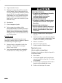
POTENTIAL HAZARD
• Engine exhaust contains carbon monoxide,
which is an odorless, deadly poison.
WHAT CAN HAPPEN
• Carbon monoxide can kill you and is also
known to the State of California to cause
birth defects.
HOW TO AVOID THE HAZARD
• Do not run engine indoors or in an enclosed
area.
This mower is designed for cutting and recycling
grass or, when equipped with a grass bag, for
catching cut grass. Any use for purposes other than
these could prove dangerous to user or bystanders.
Note: This engine is NOT equipped with a
spark arrester muffler. Use or operation
of this mower in the State of California
on any forest-covered, brush-covered
or unimproved grass-covered land,
without an approved spark arrester
muffler, is a violation of the law. Other
states may have similar laws.
General Operation
1. Read this manual carefully before operating the
mower. Become familiar with the controls and
proper use of the mower. Never allow children
under 16 years of age to operate the mower.
Never allow adults to operate mower without
proper instructions.
2. The operator of the mower is responsible for
keeping everyone, especially children and pets,
away from area of operation. The operator is
responsible for accidents or hazards occurring to
other people or their property.
3. Thoroughly inspect area where mower will be
used and remove sticks, stones, wire, and debris.
Watch for foreign objects while mowing.

EN–3
4. Wear long pants and substantial shoes. Do not
operate mower while wearing open-toed shoes,
jewelry, loose clothing or when barefoot.
5. Check fuel level before starting engine. Because
fuel is highly flammable, handle it carefully.
A. Use an approved container.
B. Fill fuel tank outdoors, not indoors.
NEVER ADD FUEL TO AN ENGINE
THAT IS RUNNING OR HOT.
C. Install gas cap on fuel container and gas
tank, and wipe up any spilled gasoline
before starting engine.
D. Do not smoke while refueling.
6. Keep all guards, shields, grass catchers and
safety devices in place. Repair or replace
damaged parts, including decals. Check all
safety devices before each use.
7. Before using, always visually inspect to see that
the blades, blade fasteners and cutter assembly
are not worn or damaged. Replace worn or
damaged blades and fasteners in sets to preserve
balance.
8. Traction drive (self-propelled model), blade and
engine are designed to stop when control bar is
released. Ensure control and brake function
properly before each use of mower.
9. Disengage the self-propelled mechanism or drive
clutch (self-propelled model) before starting the
engine.
While Operating
1. Do not run engine indoors.
2. Start the engine carefully according to
instructions and with feet well away from the
blade.
3. Always maintain secure footing. Keep a firm
grip on the handle and walk; never run. Never
operate mower in wet grass. Mow only in
daylight or in good artificial light.
4. Mow across the face of slopes; never up and
down. Use extreme caution when changing
direction on slopes. Do not mow excessively
steep slopes. Wear skid resistant shoes on slopes.
5. Always wear safety glasses or eye shields during
operation to protect eyes from foreign objects
that may be thrown from the machine. Wearing
of hearing protection, protective gloves and a
safety helmet is advisable.
6. Keep face, hands, and feet away from the mower
housing and cutter blade when the engine is
running. Blade can cause injury to hands and
feet. Stay behind the handle until the engine
stops.
7. Use extreme caution when reversing or pulling
the mower towards you.
8. Since the blade rotates for a few seconds after
the control bar is released, stay behind the
handle until the engine stops.
9. When bagging grass, stop engine and stay
behind handle until all moving parts stop before
removing and emptying bag.
10. When mowing, ensure grass bag is installed over
discharge opening.
11. Shut engine off and stay behind handle until all
moving parts stop before unclogging chute.
12. After striking a foreign object or if mower
vibrates abnormally, stop engine and remove
wire from spark plug. Check mower for damage
and make all repairs before using mower again.
If major repairs are ever needed or if assistance
is desired, contact your local Authorized Toro
Service Dealer.
13. Stop the engine and wait for all moving parts to
stop before adjusting the height-of-cut.
14. Stop the blade when pushing the mower outside
the lawn area.

EN–4
15. Stop engine before leaving the operator’s
position – behind the handle. Disconnect wire
from spark plug if mower will be unattended.
16. Do not touch engine while it is running or
shortly after it is stopped because engine will be
hot enough to cause a burn.
17. Refuel only when engine is cool.
18. If mower must be lifted to be transported, turn
off engine and stay behind the handle until all
moving parts stop.
Maintenance
1. Perform only those maintenance instructions
described in this manual. If major repairs are
ever needed or if assistance is desired, contact
your local Authorized Toro Service Dealer.
2. Before mower is cleaned, inspected, serviced, or
adjusted, stop engine and disconnect wire from
spark plug. Keep wire away from plug to prevent
accidental starting.
3. To ensure the mower is in safe operating
condition, frequently check and keep all nuts,
bolts, and screws tight. Ensure blade bolt is
tightened to 40-50 ft.-lbs. (54-68 Nm).
4. When servicing blade, refer to blade
maintenance section for correct installation and
servicing procedures.
5. To reduce fire hazard, keep engine free of
excessive grease, grass, leaves, and
accumulations of dirt.
6. Do not overspeed the engine by changing
governor settings.
7. Check grass catcher bag frequently for wear or
deterioration. Replace with a new bag when
worn or damaged for your protection.
8. Allow engine to cool before storing mower in
any enclosure. Do not store mower near any
open flame or where gasoline fumes may be
ignited by a spark.
9. At the time of manufacture, the mower
conformed to the safety standards in effect for
rotary mowers. To ensure best performance and
continued safety certification of the mower, use
genuine TORO replacement parts and
accessories. Replacement parts and accessories
made by other manufacturers may result in
nonconformance with the safety standards, and
that could be dangerous.

EN–5
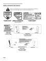
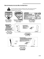
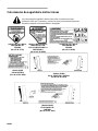
Safety and Instruction Decals
Safety decals and instructions are easily visible to the operator and are located near
any area of potential danger. Replace any decal that is damaged or lost.
ON MOWER HOUSING
(Part No. 39-5770)
UNDER COVER-DEFLECTOR
ASSEMBLY ON MOWER DECK
(Part No. 82-8450)
Model 20494
ON CONTROL PANEL
(Part No. 98–1503)
ON MOWER HOUSING
(Part No. 93-0248)
Model 20495
ON CONTROL PANEL
(Part No. 95–3013)
Model 20495
ON BATTERY
(Part No. 92–8659)

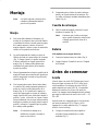
EN–6
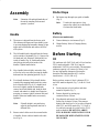
Assembly
Note: Determine left and right hand sides of
the unit by standing in the normal
operator’s position.
Handle
1. The mower is shipped from the factory with
filler between the upper and lower handle joints
to prevent shipping and assembly damage. Align
upper and lower handles and remove the filler
with a pliers.
2. The left handle knob is shipped from the factory
on the outside of the handle (Fig. 3). Remove the
left knob and bolt. Reinstall knob and bolt on
inside of handle (Fig. 4). Both handle knobs
should be positioned on the inside of the
handles. Tighten handle knobs.
3. Move handle latches slightly outward so they
will not be in the way when pivoting the handle
backward into the operating position (Fig. 4).
4. Pivot handle backward. Move handle latches
inward while snapping handle stud into center
hole of handle latch (Fig. 4). If a handle latch
does not fit tightly against the handle tube,
remove latch from handle stud, bend the latch
inward, and reattach to handle stud. Repeat as
necessary to ensure a tight fit between latch and
handle. Make sure handle knobs are securely
tightened.
Note: If handle height is not satisfactory,
adjust by placing handle stud into a
different hole.
5. Ensure control cables are to the rear and inside
of handles. Secure cables to handle with cable
ties (Fig. 4).
Starter Rope
1. Pull starter rope through rope guide on handle
(Fig. 5).
Note: To make the rope easier to loop,
squeeze the control bar on the handle
to release the blade brake.
Battery
(Electric start models only)
1. Connect battery to wire harness (Fig. 6).
2. Charge Battery. Refer to Charging Battery
section.
Before Starting
Oil
Fill crankcase with SAE 30 oil until oil level reaches
FULL mark on dipstick. 10W-30 oil may be
substituted if SAE 30 is not available. The maximum
crankcase capacity is 20 ounces (0.6 liters) of oil.
Use any high quality detergent oil having the
American Petroleum Institute (API) “service
classification”—SF, SG, SH or SJ.
Before each use, ensure oil level is between FULL
and ADD marks on dipstick (Fig. 7). Add oil if level
is low.
1. Position mower on level surface and clean
around oil dipstick (Fig. 7).
2. Remove dipstick by rotating cap
counterclockwise 1/4 turn.
3. Wipe dipstick and insert it into filler neck.
Rotate cap clockwise 1/4 turn. Then remove
dipstick and check level of oil on side of dipstick
with FULL and ADD marks (Fig. 7). If level is
low, add only enough oil to raise level to FULL
mark on dipstick. DO NOT FILL ABOVE
FULL MARK BECAUSE ENGINE COULD
BE DAMAGED WHEN STARTED. POUR
OIL SLOWLY.

EN–7
4. Insert dipstick into filler neck and rotate cap
clockwise 1/4 turn to lock.
Note: Check oil level each time mower is
used or after every 5 operating hours.
Initially, change oil after the first 5
hours of operation; thereafter, change
oil after every 50 hours of operation.
More frequent oil changes are required
in dusty or dirty conditions.
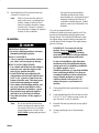
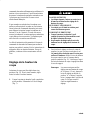
Gasoline
POTENTIAL HAZARD
• In certain conditions gasoline is extremely
flammable and highly explosive.
WHAT CAN HAPPEN
• A fire or explosion from gasoline can burn
you, others, and cause property damage.
HOW TO AVOID THE HAZARD
• Use a funnel and fill the fuel tank outdoors,
in an open area, when the engine is cold.
Wipe up any gasoline that spills.
• Do not fill the fuel tank completely full.
Add gasoline to the fuel tank until the level
is 1/4” to 1/2” (6 mm to 13 mm) below the
bottom of the filler neck. This empty space
in the tank allows gasoline to expand.
• Never smoke when handling gasoline, and
stay away from an open flame or where
gasoline fumes may be ignited by a spark.
• Store gasoline in an approved container
and keep it out of the reach of children.
• Never buy more than a 30-day supply of
gasoline.
Note: Do not use gasoline that has been
stored in an approved container from
one season to the next. Toro strongly
recommends the use of fresh, clean,
UNLEADED
regular grade gasoline in
Toro gasoline powered products.
Unleaded gasoline burns cleaner,
extends engine life, and promotes good
starting by reducing the build-up of
combustion chamber deposits. Leaded
gasoline can be used if unleaded is not
available.
Toro also recommends that Toro
Stabilizer/Conditioner be used regularly in all Toro
gasoline powered products during operation and
storage seasons. Toro Stabilizer/Conditioner cleans
the engine during operation and prevents gum-like
varnish deposits from forming in the engine during
periods of storage.
IMPORTANT: Do not mix oil with the
gasoline. Never use methanol
, gasoline
containing methanol, gasohol containing
more than 10% ethanol or white gas because
engine fuel system damage could result.
Do not use fuel additives other than those
manufactured for fuel stabilization during
storage such as Toro’s Stabilizer/conditioner
or a similar product. Toro’s
Stabilizer/conditioner is a petroleum distillate
based conditioner/stabilizer. Toro does not
recommend stabilizers with an alcohol base
such as ethanol, methanol or isopropyl.
Additives should not be used to try to
enhance the power or performance of
machine.
1. Clean around fuel tank cap and remove cap from
tank (Fig. 7).
2. Using unleaded gasoline, fill fuel tank to within
1/4” to 1/2” (6 to 13 mm) from top of tank, not
into filler neck. Do not fill tank full.
3. Reinstall fuel tank cap and wipe up any spilled
gasoline.
4. Connect spark plug wire (if disconnected)
(Fig. 7).

EN–8
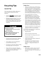
Recycling Tips
General Tips
Follow these instructions whether cutting grass or
leaves for the best cutting results and lawn
appearance:
• Maintain a sharp blade
throughout the cutting
season. Periodically file down nicks on blade.
• Only mow dry grass or leaves. Wet grass and
leaves tend to clump on yard and may cause
mower to plug or engine to stall. They may also
be slippery to walk on and could cause you to
slip and fall.
POTENTIAL HAZARD
• Wet grass or leaves can cause you to slip
and contact blade.
WHAT CAN HAPPEN
• Blade contact can seriously injure you.
HOW TO AVOID THE HAZARD
• Mow only in dry conditions.
• Set engine speed to fastest position. Maximum
horsepower provides best cutting results.
• Clean clippings or leaves from underside of
mower deck after each mowing.
• Keep engine in good running condition. Cutting
and recutting requires more horsepower.
• Clean air filter more frequently. Cutting and
recutting stirs up more clippings and dust which
clogs the air filter and reduces engine
performance.
Cutting Grass
• Grass grows at different rates at different times
of the year. In the heat of summer, it is generally
best to cut grass at the C, D or E height-of-cut
settings. Only about !/3 of the grass blade should
be cut off. Cutting below the C inch setting is
not recommended unless grass is sparse or it is
late fall when grass growth begins to slow down.
• When changing height-of-cut from the
established setting (ex. C, D or E) to a new
height, the grass may appear ragged or uneven
until the grass adjusts to the new established
height-of-cut and regains its normal appearance.
• When cutting grass over six inches tall, you may
want to first mow using the highest height-of-cut
setting and a slower walking speed; then mow
again at a lower setting for best lawn appearance.
If grass is too long and leaves clumps on top of
lawn, mower may plug and cause engine to stall.
• Alternate mowing direction. This helps disperse
clippings over lawn for even fertilization.
If the finished cut lawn appearance is unsatisfactory,
try one or more of the following:
• Sharpen the blade.
• Walk at a slower pace while mowing.
• Raise the height-of-cut setting on your mower.
• Cut grass more frequently.
• Overlap cutting swaths instead of cutting a full
swath with each pass.
• Set height-of-cut on front wheels one notch
lower than rear wheels. (example: set front
wheels at “C” setting and rear wheels at “D”
setting)
Cutting Leaves
• When cutting is complete, always be sure that
50% of the lawn shows through the cut leaf
cover. This may require one or more passes over
the leaves.

EN–9
• For light leaf coverage, position all wheels at the
same height-of-cut setting.
• If there are more than five inches of leaves on
lawn, set the front wheels one or two notches
higher than the rear wheels. This makes it easier
to feed leaves under mower deck.
• Walk at a slower mowing speed if leaves are not
being cut up finely enough to be hidden down in
the grass.
• If you cut up a lot of oak leaves, you might want
to add lime to your grass in the spring. Lime
reduces the acidity of oak leaves.
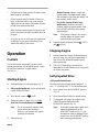
Operation
Controls
Key switch (electric start model), throttle control,
ground speed control (self-propelled model), control
bar and recoil starter are on upper handle
(Fig. 8 & 9).
Starting Engine
1. Push spark plug wire onto spark plug (Fig. 7).
2. Self-propelled model only–Move ground speed
control to N (NEUTRAL).
3. Move throttle control to
(FAST).
4. Push primer three (3) times (Fig. 10). Wait
about two (2) seconds between each push.
Note: Do not use primer to restart a warm
engine after a short shutdown.
However, cool weather may require
priming to be repeated.
5. Start the mower:
• Manual Starting: Squeeze control bar
against handle. Pull starter handle lightly
until resistance is felt, then pull sharply. Let
rope return to handle slowly.
• Key-lectric Starting (Electric start
models only): Insert key into switch.
Squeeze control bar against handle. Turn
key to START and release when engine
begins running.
Note: If the battery’s charge is too weak to
start the engine, the engine can be
started with the recoil starter.
6. Regulate throttle as desired between
(FAST)
and (SLOW).
Stopping Engine
1. Release control bar. Engine, blade and traction
drive will stop. See your dealer immediately if
they do not. Stay behind the handle until all
moving parts stop.
2. Pull wire off spark plug if mower will be
unattended or not used. Remove key from switch
on electric start model.
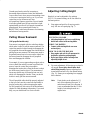
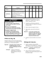
Self-propelled Drive
(Self-propelled models only)
The mower has three ground speeds: number “1” is
slow, “2” is medium, and “3” is a fast walking pace.
1. Move control bar to the RUN/SHIFT position
(Fig. 11).
2. Move ground speed control to desired setting.
3. To engage the self-propel drive, squeeze the
control bar against the handle to the
RUN/DRIVE position (Fig. 11).
Note: Do not shift speeds while control bar is
squeezed against handle in the
RUN/DRIVE position (Fig. 11); the
transmission could be damaged. Move
control bar to the RUN/SHIFT position
when changing ground speed.
La page charge ...
La page charge ...
La page charge ...
La page charge ...
La page charge ...
La page charge ...
La page charge ...
La page charge ...
La page charge ...
La page charge ...
La page charge ...
La page charge ...
La page charge ...
La page charge ...
La page charge ...
La page charge ...
La page charge ...
La page charge ...
La page charge ...
La page charge ...
La page charge ...
La page charge ...
La page charge ...
La page charge ...
La page charge ...
La page charge ...
La page charge ...
La page charge ...
La page charge ...
La page charge ...
La page charge ...
La page charge ...
La page charge ...
La page charge ...
La page charge ...
La page charge ...
La page charge ...
La page charge ...
La page charge ...
La page charge ...
La page charge ...
La page charge ...
La page charge ...
La page charge ...
La page charge ...
La page charge ...
La page charge ...
La page charge ...
La page charge ...
La page charge ...
La page charge ...
La page charge ...
La page charge ...
La page charge ...
La page charge ...
La page charge ...
La page charge ...
La page charge ...
La page charge ...
La page charge ...
La page charge ...
La page charge ...
La page charge ...
La page charge ...
La page charge ...
La page charge ...
La page charge ...
La page charge ...
La page charge ...
La page charge ...
La page charge ...
La page charge ...
La page charge ...
La page charge ...
La page charge ...
La page charge ...
-
 1
1
-
 2
2
-
 3
3
-
 4
4
-
 5
5
-
 6
6
-
 7
7
-
 8
8
-
 9
9
-
 10
10
-
 11
11
-
 12
12
-
 13
13
-
 14
14
-
 15
15
-
 16
16
-
 17
17
-
 18
18
-
 19
19
-
 20
20
-
 21
21
-
 22
22
-
 23
23
-
 24
24
-
 25
25
-
 26
26
-
 27
27
-
 28
28
-
 29
29
-
 30
30
-
 31
31
-
 32
32
-
 33
33
-
 34
34
-
 35
35
-
 36
36
-
 37
37
-
 38
38
-
 39
39
-
 40
40
-
 41
41
-
 42
42
-
 43
43
-
 44
44
-
 45
45
-
 46
46
-
 47
47
-
 48
48
-
 49
49
-
 50
50
-
 51
51
-
 52
52
-
 53
53
-
 54
54
-
 55
55
-
 56
56
-
 57
57
-
 58
58
-
 59
59
-
 60
60
-
 61
61
-
 62
62
-
 63
63
-
 64
64
-
 65
65
-
 66
66
-
 67
67
-
 68
68
-
 69
69
-
 70
70
-
 71
71
-
 72
72
-
 73
73
-
 74
74
-
 75
75
-
 76
76
-
 77
77
-
 78
78
-
 79
79
-
 80
80
-
 81
81
-
 82
82
-
 83
83
-
 84
84
-
 85
85
-
 86
86
-
 87
87
-
 88
88
-
 89
89
-
 90
90
-
 91
91
-
 92
92
-
 93
93
-
 94
94
-
 95
95
-
 96
96


Toro 20493 Manuel utilisateur
- Catégorie
- Tondeuses à gazon
- Taper
- Manuel utilisateur
dans d''autres langues
- English: Toro 20493 User manual
- español: Toro 20493 Manual de usuario
Documents connexes
-
Toro 48cm Rear Bagging Lawnmower Manuel utilisateur
-
-
Toro Vacu-Power Mower, V-21SB Manuel utilisateur
-
-
Toro Lawnmower Manuel utilisateur
-
-
-
Toro Recycler Mower, R-21S1B Manuel utilisateur
-
Toro 48cm Recycler/Rear Bagging Lawnmower Manuel utilisateur
-
Toro Super Recycler Lawnmower Manuel utilisateur
