Toro 48cm Recycler/Rear Bagging Lawnmower Manuel utilisateur
- Catégorie
- Tondeuses à gazon
- Taper
- Manuel utilisateur

Operator’s Manual Mode d’emploi
FORM NO. 3319–328
48cm
Recycler
Mower
Model No. 20804–7900001 & Up
Model No. 20809–7900001 & Up
Recycleur
de 48 cm
Tondeuse
Modèle n° 20804 – 7900001 et suivants
Modèle n° 20809 – 7900001 et suivants

EThe Toro Company – 1997
All Rights Reserved
Printed in USA
i
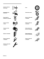
Figures
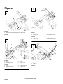
1332
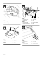
1
English
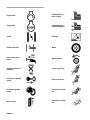
1. Model
and serial number engraved in mower housing
Français
1. Numéros
de modèle et de série gravés sur le
carter de tondeuse
English
1. Handle
2. Mounting
bracket
3. Knobs
4.
Housing pocket
Français
1. Guidon
2.
Support de montage
3.
Boutons seulement
4.
Poche du carter
English
1.
Cable tie
2.
Throttle cable
3. *T
raction cable
(*Self–propelled model)
Français
1. Serre-câble
2.
Câble des gaz
3.
Câble d’embrayage
(modèles autopropulsés)
English
1.
Cable tie
Français
1. Serre-câble
1
2
3
4

ii
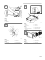
1339
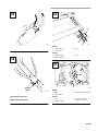
English
1. Plug
Français
1. Obturateur
M–2950
1
2
English
1.
Rope guide
2.
Starter rope
Français
1. Guide-câble 2.
Câble de démarreur
1159
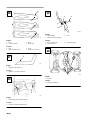
English
1. Dipstick
2.
Fuel tank cap
3.
ADD mark
4.
FULL mark
Français
1. Jauge
2.
Bouchon du réservoir de
carburant
3.
Repère ADD (ajouter)
4.
Repère FULL (plein)
1344
1 2
English
1. Primer 2.
Spark plug wire
Français
1. Amorceur 2.
Fil de bougie
5
6
7
8

iii
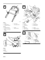
M–2951
4
3
1
2
English
1. Throttle
2.
Blade control bar
3.
Self-propel control bar*
4.
Recoil starter
*
Self-propelled model
Français
1.
Commande des gaz
2.
Barre de commande de
lame
3.
Barre de commande de
traction*
4. Lanceur
*
modèle autotracté
1339
English
1. Plug
Français
1. Obturateur
775
1
3
5
2
6
English
1.
Bag door
2.
Bag ramp
3.
Discharge door
4.
Bag handle
5.
Mounting bracket
6.
Bag frame hook
Français
1. V
olet du sac
2.
Armature du sac
3. V
olet de décharge
4. Poignée
5.
Support de montage
6.
Crochet du cadre du sac
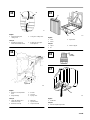
1334
9
10
11
12

iv
971
English
1.
Sparse/normal grass
cutting scale
2.
Lush grass cutting scale
Français
1.
Échelle de coupe pour
herbe clairsemée/normale
2.
Echelle de coupe pour
herbe épaisse
1336
English
1.
Height–of–cut adjustment
lever
2.
Height settings
3. Pointer
4.
Link rod
5.
Spring cover
Français
1.
Levfer de réglage de le
hauteur de coupe
2.
Hauteurs de coupe
3. Marqueur
4. T
ige de liaison
5.
Capot à ressorts
1003
English
1. Cover
2. Screw
3.
Paper filter
Français
1. Capot
2. Vis
3.
Filtre en papier
.030”
(.76 mm)
1782
English
1.
OIl fill tube
Français
1. T
ube de remplissage d’huile
13
14
15
16
17

v
1328
English
1.
Drain opening
Français
1.
Orifice de vidange
1329
English
1. Cover 2.
Screws (2)
Français
1. Capot 2. V
is (2)
2348
English
1.
Cable clamp screw
2.
Throttle cable
3.
Throttle lever
4. Stop
Français
1. V
is du serre-câble
2.
Câble de commande des
gaz
3.
Levier d’accélérateur
4. Butée
2341
English
1.
Adjustment knob
2.
Control cable
Français
1.
Bouton de réglage
2.
Câble de commande
18
19
20
21

vi
2343
M–2948
3,2 mm
(1/8”)
Self-propelled model shown
Modèle autotracté représenté
2341
1
2
3
English
1.
Cable conduit
2.
Cable bracket
3. Nut
Français
1.
Gaîne du câble
2.
Support du câble
3. Ecrou
1330
English
1. Blade
2.
Blade stif
fener
3. Blade
bolt and lockwasher
Français
1. Lame
2. Renfort
de lame
3.
Boulon et rondelle de
blocage de la lame
22
23
24
25

vii
270
A
B
C
1
2
3
4
English
1. Sail
2.
Flat part of blade
3. Wear
4.
Slot formed
Français
1. Pale
2.
Partie plate de la lame
3. Usure
4.
Encoche due à l’usure
153
1
English
1.
Sharpen at this angle only
Français
1.
Aiguisez à cet angle seulement
782
1
1
English
1.
Grease fitting (self–propelled model)
Français
1.
Graisseur (modèles autopropulsès)
1
2
3
m-2858
English
1. W
ashout fitting
2.
Quick disconnect coupling
3. Hose
Français
1.
Raccord de rinçage
2.
Raccord rapide
3. T
uyau d’arrosage
1330
English
1. Kickers
Français
1.
Plaques de deflection
26
27
28
29
30

GB–1
Contents
Page
Introduction 1.
. . . . . . . . . . . . . . . . . . . . . . . . . . .
Safety 2
. . . . . . . . . . . . . . . . . . . . . . . . . . . . . . . . .
Training 2
. . . . . . . . . . . . . . . . . . . . . . . . . . .
Preparation 2
. . . . . . . . . . . . . . . . . . . . . . . . .
Operation 2
. . . . . . . . . . . . . . . . . . . . . . . . . .
Maintenance And Storage 3
. . . . . . . . . . . . .
Sound Pressure Level 4
. . . . . . . . . . . . . . . . .
Sound Power Level 4
. . . . . . . . . . . . . . . . . .
Vibration Level 4
. . . . . . . . . . . . . . . . . . . . .
Symbol Glossary
4
. . . . . . . . . . . . . . . . . . . .
Assembly 7
. . . . . . . . . . . . . . . . . . . . . . . . . . . . . .
Install Handle 7
. . . . . . . . . . . . . . . . . . . . . . .
Install Discharge Tunnel Plug 7
. . . . . . . . . .
Install Starter Rope 7
. . . . . . . . . . . . . . . . . .
Before Starting 7
. . . . . . . . . . . . . . . . . . . . . . . . . .
Fill Crankcase With Oil 7
. . . . . . . . . . . . . . .
Fill Fuel Tank W
ith Gasoline
8
. . . . . . . . . . .
Recycling Tips 9
. . . . . . . . . . . . . . . . . . . . . . . . . .
General Tips 9
. . . . . . . . . . . . . . . . . . . . . . . .
Cutting Grass
9
. . . . . . . . . . . . . . . . . . . . . . .
Cutting Leaves
10
. . . . . . . . . . . . . . . . . . . . . .
Operation 10
. . . . . . . . . . . . . . . . . . . . . . . . . . . . . .
Starting, Stopping And Self–propelling 10
. . .
Using Dischar
ge Tunnel Plug 10
. . . . . . . . . .
Using Grass Bag
11
. . . . . . . . . . . . . . . . . . . . .
Setting Height-of-Cut 11
. . . . . . . . . . . . . . . . .
Maintenance 12
. . . . . . . . . . . . . . . . . . . . . . . . . . . .
Servicing Air Cleaner 12
. . . . . . . . . . . . . . . .
Replacing Spark Plug 12
. . . . . . . . . . . . . . . . .
Draining Gasoline 13
. . . . . . . . . . . . . . . . . . .
Changing Crankcase Oil
13
. . . . . . . . . . . . . .
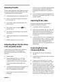
Adjusting Throttle 14
. . . . . . . . . . . . . . . . . . .
Adjusting Wheel Traction Drive
(self–propelled model) 14
. . . . . . . . . . . . . .
Adjusting Brake Cable
14
. . . . . . . . . . . . . . . .
Inspecting/Removing/ Sharpening Blade
14
.
Lubrication 15
. . . . . . . . . . . . . . . . . . . . . . . . .
Cleaning Mower Housing
15
. . . . . . . . . . . . .
Storage 16
. . . . . . . . . . . . . . . . . . . . . . . . . . . . . . . .
Introduction
Thank you for purchasing a Toro product.
All of us at Toro want you to be completely satisfied
with your new product, so feel free to contact your
local Authorized Service Dealer for help with service,
genuine Toro parts, or other information you may
require.
Whenever you contact your Authorized Service
Dealer or the factory, always know the model and
serial numbers of your product. These numbers will
help the Service Dealer or Service Representative
provide exact information about your specific
product. You will find the model and serial number
decal located in a unique place on the product
(Fig. 1).
For your convenience, write the product model and
serial numbers in the space below.
Model No:
Serial No.
Read this manual carefully to learn how to operate
and maintain your product correctly. Reading this
manual will help you and others avoid personal injury
and damage to the product. Although Toro designs,
produces and markets safe, state-of-the-art products,
you are responsible for using the product properly
and safely. You are also responsible for training
persons who you allow to use the product about safe
operation.
The Toro warning system in this manual identifies
potential hazards and has special safety messages that
help you and others avoid personal injury, even death.
DANGER, WARNING and CAUTION are signal
words used to identify the level of hazard. However,
regardless of the hazard, be extremely careful.
DANGER signals an extreme hazard that will cause
serious injury or death if the recommended
precautions are not followed.

GB–2
WARNING signals a hazard that may cause serious
injury or death if the recommended precautions are
not followed.
CAUTION signals a hazard that may cause minor or
moderate injury if the recommended precautions are
not followed.
Two other words are also used to highlight
information. “Important” calls attention to special
mechanical information and “Note” emphasizes
general information worthy of special attention.
The left and right side of the machine is determined
by standing behind the handle in the normal
operator’s position.
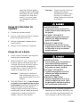
Safety
Training
1. Read the instructions carefully. Be familiar with
the controls and the proper use of the equipment.
2. Never allow children or people unfamiliar with
these instructions to use the lawnmower. Local
regulations may restrict the age of the operator.
3. Never mow while people, especially children, or
pets are nearby.
4. Keep in mind that the operator or user is
responsible for accidents or hazards occurring to
other people or their property.
Preparation
1. While mowing, always wear substantial
footwear and long trousers. Do not operate the
equipment when barefoot or wearing open
sandals.
2. Always wear safety glasses or eye shields during
operation to protect eyes from foreign objects
that may be thrown from the machine. Wearing
of hearing protection, protective gloves and a
safety helmet is advisable.
3. Thoroughly inspect the area where the
equipment is to be used and remove all objects
which may be thrown by the machine.
4. WARNING – Petrol is highly flammable.
• Store fuel in containers specifically designed for
this purpose.
• Refuel outdoors only and do not smoke while
refuelling.
• Add fuel before starting the engine. Never
remove the cap of the fuel tank or add petrol
while the engine is running or when the engine is
hot.
• If petrol is spilled, do not attempt to start the
engine but move the machine away from the area
of spillage and avoid creating any source of
ignition until petrol vapors have dissipated.
• Replace all fuel tanks and container caps
securely.
5.
Replace faulty silencers.
6. Before using, always visually inspect to see that
the blades, blade bolts and cutter assembly are
not worn or damaged. Replace worn or damaged
blades and bolts in sets to preserve balance.
7. On multi-bladed machines, take care as rotating
one blade can cause other blades to rotate.
Operation
1. Do not operate the engine in a confined space
where dangerous carbon monoxide fumes can
collect.
2. Mow only in daylight or in good artificial light.
3. Avoid operating the equipment in wet grass,
where feasible.
4. Always be sure of your footing on slopes.
5. Walk, never run.
6. For wheeled rotary machines, mow across the
face of slopes, never up and down.

GB–3
7. Exercise extreme caution when changing
direction on slopes.
8.
Do not mow excessively steep slopes.
9. Use extreme caution when reversing or pulling
the lawnmower towards you.
10. Stop the blade(s) if the lawnmower has to be
tilted for transportation when crossing surfaces
other than grass, and when transporting the
lawnmower to and from the area to be mowed.
11. Never operate the lawnmower with defective
guards or shields, or without safety devices, for
example deflectors and/or grass catchers, in
place.
12. Do not change the engine governor settings or
overspeed the engine.
13. Disengage all blade and drive clutches before
starting the engine.
14. Start the engine or switch on the motor carefully
according to instructions and with feet well away
from the blade(s).
15. Do not tilt the lawnmower when starting the
engine or switching on the motor, except if the
lawnmower has to be tilted for starting. In this
case, do not tilt it more than absolutely necessary
and lift only the part which is away from the
operator.
16. Do not start the engine when standing in front of
the discharge chute.
17. Do not put hands or feet near or under rotating
parts. Keep clear of the discharge opening at all
times.
18. Never pick up or carry a lawnmower while the
engine is running.
19. Stop the engine and disconnect the spark plug
wire.
• before clearing blockages or unclogging chute;
• before checking, cleaning or working on the
lawnmower;
• after striking a foreign object. Inspect the
lawnmower for damage and make repairs before
restarting and operating the lawnmower;
• if lawnmower starts to vibrate abnormally (check
immediately).
20. Stop the engine
• whenever you leave the lawnmower;
• before refuelling.
21. Reduce the throttle setting during engine shut
down and, if the engine is provided with a
shut-off valve, turn the fuel off at the conclusion
of mowing.
22. Go slow when using a trailing seat.
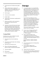
Maintenance
And Storage
1. Keep all nuts, bolts and screws tight to be sure
the equipment is in safe working condition.
2. Never store the equipment with petrol in the tank
inside a building where fumes may reach an
open flame or spark.
3. Allow the engine to cool before storing in any
enclosure.
4. To reduce the fire hazard, keep the engine,
silencer, battery compartment and petrol storage
area free of grass, leaves, or excessive grease.
5. Check the grass catcher frequently for wear or
deterioration.
6. Replace worn or damaged parts for safety.
7. If the fuel tank has to be drained, this should be
done outdoors.

GB–4
Sound
Pressure Level
Model 20804
This unit has an equivalent continuous A-weighted
sound pressure at the operator ear of: 83 dB(A), based
on measurements of identical machines per ANSI
B71.5-1984 procedures.
Model 20809
This unit has an equivalent continuous A-weighted
sound pressure at the operator ear of: 82 dB(A), based
on measurements of identical machines per ANSI
B71.5-1984 procedures.
Sound
Power Level
This unit has a sound power level of: 96 dB(A)/1 pW,
based on measurements of identical machines per
Directive 84/538/EEC and amendments.
Vibration
Level
Model 20804
This unit has a maximum hand-arm vibration level of
9.4 m/s@, based on measurement of identical
machines per ISO 5349 procedures.
Model 20809
This unit has a maximum hand-arm vibration level of
5.5 m/s@, based on measurement of identical
machines per ISO 5349 procedures.
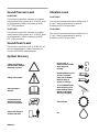
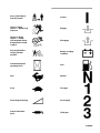
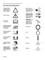
Symbol
Glossary
Safety
alert triangle —
symbol within triangle
indicates a hazard.
Do not open or
remove safety shields
while engine is
running.
Safety alert symbol
Rotating blade can cut
off toes or fingers.
Stay clear of mower
blade as long as
engine is running.
Read operator
’s
manual.
To avoid blade failure
when mulching, use
blade stiffener when
mower is equipped
with mulching plug.
Consult technical
manual for proper
service procedures.
Transmission
Stay a safe distance
from the machine.
Oil

GB–5
Stay a safe distance
from the mower
.
On/Run
Throw or flying
objects — Whole body
exposure
Engage
Thrown or flying
objects — Rotary
side-mounted mower
.
Keep deflector shield
in place.
Disengage
Stop engine before
leaving operator
position.
Battery charging
condition
Hourmeter/elapsed
operating hours
Fuel
Fast Neutral
Slow
First gear
Decreasing/Increasing
Second gear
Grease lubrication
point
Third gear

GB–6
Engine start
Cutting element —
basic symbol
Engine stop
Cutting element —
height adjustment
Choke
Pull rope.
Primer (start aid)
Wheel
Push primer three
times.
Wheel traction
Properly dispose of
batteries.
Lower control bar
.
Insert key in ignition
switch.
Raise control bar
.
Turn key in ignition
switch.
Raise/lower control
bar.
Move control.
Raise/lower control
bar.

GB–7
Raise control bar
.
Raise control bar
.
Lower control bar
.
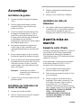
Assembly
Install
Handle
1. INSTALLING HANDLE—Loosen knobs on
mounting brackets (Fig. 2).
2. Position mounting brackets in a vertical position
so that holes face up.
3. Slide handle ends into holes in mounting
brackets until handle ends are completely seated
in brackets (Fig. 2). Make sure throttle cable and
traction cable (self–propelled model) are
positioned on top of left mounting bracket
(Fig. 3).
4. Rotate handle and mounting brackets rearward
until brackets fit securely into housing pockets
(Fig. 3).
5. Tighten knobs until edges of slots on top of
mounting brackets touch.
6. Use cable tie to secure cable(s) to lower side of
left hand tube (Fig. 4). Cable tie should be
positioned 25 mm (1”) from bend in handle. See
Figure 4 for correct cable placement.
7. Cut excess length from cable tie on lower left
handle.
Note: Make sure cable(s) do not interfere
with the raising or lowering of
discharge door.
Install
Discharge T
unnel Plug
1. Make sure engine is off.
2.
Open dischar
ge door and insert plug into
discharge tunnel opening (Fig. 5).
3. Push plug all the way into the discharge tunnel
opening.
4. Lower discharge door over plug.
Install
Starter Rope
1. Pull the starter rope through the rope guide on
the handle (Fig. 6). To make the rope easier to
loop, squeeze the blade control bar on the handle
(Fig. 9) to release the blade brake.
Before
Starting
Fill
Crankcase W
ith Oil
Initially, crankcase must be filled with 0.6 L
(20 ounces) of SAE 30 oil. Use any high quality
detergent oil having the American Petroleum Institute
(API) “service classification”—SF, SG or SH.
Before each use, assure oil level is between ADD and
FULL mark (Fig. 7). Add oil if level is low.
1. Position mower on level surface and clean
around oil dipstick.

GB–8
2. Remove dipstick by rotating cap
counterclockwise 1/4 turn.
3. Wipe dipstick and insert it into filler neck.
Rotate cap 1/4 turn. Then remove dipstick and
check level of oil (Fig. 7). If level is low, add
only enough oil to raise level to FULL mark on
dipstick.
DO NOT FILL ABOVE FULL
MARK BECAUSE ENGINE COULD BE
DAMAGED WHEN ST
ARTED. POUR OIL
SLOWLY.
Note: Check oil level each time mower is
used or after every 5 hours of mower
operation. Initially, change oil after the
first 5 hours of operation; thereafter,
change oil after every 50 hours of
operation. More frequent oil changes
are required in dusty or dirty
conditions.
4. Insert dipstick into filler neck and rotate cap
clockwise 1/4 turn to lock it in place.
Fill
Fuel T
ank W
ith Gasoline
POTENTIAL
HAZARD
• In certain conditions gasoline is extremely
flammable and highly explosive.
WHAT CAN HAPPEN
• A fire or explosion from gasoline can burn
you, others, and cause property damage.
HOW TO AV
OID THE HAZARD
• Use a funnel and fill the fuel tank outdoors,
in an open area, when the engine is cold.
Wipe up any gasoline that spills.
• Do not fill the fuel tank completely full.
Add gasoline to the fuel tank until the level
is 6 mm to 13 mm (1/4” to 1/2”) below the
bottom of the filler neck. This empty space
in the tank allows gasoline to expand.
• Never smoke when handling gasoline, and
stay away from an open flame or where
gasoline fumes may be ignited by a spark.
• Store gasoline in an approved container
and keep it out of the reach of children.
• Never buy more than a 30-day supply of
gasoline.
Note: The Toro Company strongly
recommends the use of fresh, clean,
UNLEADED regular grade gasoline in
Toro gasoline powered products.
Unleaded gasoline burns cleaner,
extends engine life, and promotes good
starting by reducing the build–up of
combustion chamber deposits. Leaded
gasoline can be used if unleaded is not
available.
1. Clean around fuel tank cap and remove cap from
tank (Fig. 7). Do not fill tank full. Using
unleaded gasoline, fill fuel tank to within 6 to 13
mm (1/4” to 1/2”) from top of tank, not into
filler neck.
2. Install fuel tank cap and wipe up any spilled
gasoline.

GB–9
IMPORTANT: Do not mix oil with the
gasoline. Do not use gasoline that has been
stored in an approved container from one
season to the next.
Toro recommends that a fuel stabilizer be used
regularly in all Toro gasoline powered products
during operation and storage seasons. Stabilizers
clean the engine during operation and prevent
gum-like varnish deposits from forming in the
engine during periods of storage.
IMPORTANT: Some fuels, called oxygenated
or reformulated gasolines, ar
e gasolines
blended with alcohols or ethers. Excessive
amounts of these blends can damage the fuel
system or cause performance problems. Never
use methanol
, gasoline containing methanol,
gasohol containing more than 10% ethanol or
white gas because engine fuel system damage
could result. If any undesirable operating
symptoms occur, use gasoline with a lower
percentage of alcohol or ether.
Do not use fuel additives other than those
manufactured for fuel stabilization during
storage such as T
oro’s Stabilizer/conditioner
or a similar product. Toro’s
Stabilizer/conditioner is a petroleum distillate
based conditioner/stabilizer. Toro does not
recommend stabilizers with an alcohol base
such as ethanol, methanol or isopropyl.
Additives should not be used to try to
enhance the power or performance of the
machine.
Recycling
T
ips
General
T
ips
Follow these instructions whether cutting grass or
leaves for the best cutting results and lawn
appearance:
• Maintain a sharp blade
throughout the cutting
season. Periodically file down nicks on blade.
• Mow only dry grass or leaves. Wet grass and
leaves tend to clump on yard and may cause
mower to plug or engine to stall. They also may
be slippery to walk on and could cause you to
slip and fall.
POTENTIAL HAZARD
• Wet grass or leaves can cause you to slip
and contact blade.
WHAT CAN HAPPEN
• Blade contact can seriously injure you.
HOW TO AV
OID THE HAZARD
• Mow only in dry condition.
• Set engine speed to fastest position. Maximum
horsepower provides best cutting results.
• Clean clippings or leaves from underside of
mower deck after each mowing.
• Keep engine in good running condition. Cutting
and recutting requires more horsepower.
• Clean air filter more frequently. Cutting and
recutting stirs up more clippings and dust which
clogs the air filter and reduces engine
performance.
Cutting
Grass
• Grass grows at different rates at different times
of the year. In the heat of the summer, it is
generally best to cut grass at the C, D or E
height-of-cut settings. Only about 1/3 of the
grass blade should be cut off. Cutting below the
C setting is not recommended unless grass is
sparse or it is late fall when grass growth begins
to slow down.
• When cutting grass over six inches tall, you may
want to first mow using the highest height-of-cut
setting and a slower walking speed; then mow
again at a lower setting for best lawn appearance.
If grass is too long and leaves clumps on top of
lawn, mower may plug and cause engine to stall.

GB–10
• Alternate mowing direction. This helps disperse
clippings over lawn for even fertilization.
If the finished cut lawn appearance is unsatisfactory,
try one or more of the following:
• Sharpen the blade.
• Walk at a slower pace while mowing.
• Raise the height-of-cut setting on your mower.
• Cut grass more frequently.
• Overlap cutting swaths instead of cutting a full
swath with each pass.
• Mow across the marginal areas a second time.
• Set height-of-cut on front wheels one notch
lower than rear wheels. (example: set front
wheels at “C” setting and rear wheels at “D”
setting)
Cutting
Leaves
• When cutting is complete, always be sure that
50% of the lawn shows through the cut leaf
cover. This may require one or more passes over
the leaves.
• For light leaf coverage, position all wheels at the
same height-of-cut setting.
• If there are more than five inches of leaves on
lawn, set the front wheels one or two notches
higher than the rear wheels. This makes it easier
to feed leaves under mower deck.
• Walk at a slower mowing speed if leaves are not
being cut up finely enough to be hidden down in
the grass.
• If you cut up a lot of oak leaves, you might want
to add lime to your grass in the spring. Lime
reduces the acidity of oak leaves.
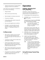
Operation
Starting,
Stopping And
Self–propelling
CONTROLS—Throttle, blade control bar,
self–propel control bar (self–propelled model only)
and recoil starter are on upper handle (Fig. 9).
1. Push spark plug wire onto spark plug (Fig. 8).
2. STARTING (Fig. 9)—Move throttle forward to
FAST position.
Push primer three (3) times (Fig. 8). Wait about
two (2) seconds between each push.
Note: Do not use primer to restart a warm
engine after a short shutdown.
However, cool weather may require
priming to be repeated.
Squeeze blade control bar against handle. Pull
recoil starter out until slack in rope is taken up.
Then pull vigorously to start the engine. When
engine starts, regulate engine speed as desired.
3. STOPPING (Fig. 9)—To stop engine, release
blade control bar. Pull wire off spark plug if
mower will be unattended or not used.
4. WHEEL TRACTION OPERATION
(self–propelled model) (Fig. 9)—Squeeze
self-propel control bar against handle to drive.
To stop the self–propel drive, release the
self-propel control bar.
Note: The drive wheels are equipped with
freewheeling clutches which enable the
mower to be pulled rearward easier
when the wheel drive is disengaged. To
disengage the clutches, mower must be
pushed forward at least 2.5 cm (1”)
after wheel drive operation has
stopped.
Using
Discharge T
unnel Plug
1. Stop engine.

GB–11
2.
Open dischar
ge door and insert plug into
discharge tunnel opening (Fig. 10).
3. Push plug all the way into the discharge tunnel
opening.
4. Lower discharge door over plug.
5. To remove the plug, raise discharge door and
pull plug out of discharge tunnel.
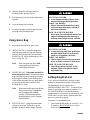
Using
Grass Bag
1. Stop engine and wait for all parts to stop.
2. INST
ALLING BAG—Raise discharge door,
slide bag ramp attached to bag into discharge
opening, and hook bag frame onto mounting
bracket (Fig. 11). Allow discharge door to rest
on top of bag (Fig. 12).
Note: Make sure grass bag door is fully
closed against grass bag before
installing bag on mower.
3.
REMOVING BAG—
Stop engine and wait for
all moving parts to stop. For protection, always
keep hands and feet away from mower housing
while engine is running. Raise discharge door.
While holding discharge door up, grasp handle
on grass bag and lift bag off mower. Allow
discharge door to close.
Note: When removing the grass bag, the bag
ramp scoops out any clippings that
may be plugging the discharge
opening. If the discharge opening
remains plugged, clear all clippings
from the mower.
4. EMPTYING BAG—Grasp bag frame handle
and rear of grass bag. Tip bag door up and
gradually tip bag forward to empty clippings.
POTENTIAL HAZARD
• Grass clippings and other objects can be
thrown from an open discharge tunnel.
WHAT CAN HAPPEN
• Objects thrown with enough force could
cause serious personal injury or death to
operator or bystander.
HOW TO AV
OID THE HAZARD
• Never open door on discharge tunnel when
engine is running unless the grass bag or
discharge tunnel plug is securely installed.
POTENTIAL HAZARD
• A worn grass bag could allow small stones
and other similar debris to be thrown in
operator’s or bystander’s direction.
WHAT CAN HAPPEN
• Thrown objects can cause serious personal
injury or death to operator or bystanders.
HOW TO AV
OID THE HAZARD
• Check the grass bag frequently. If it is
damaged, install a new genuine TORO
replacement bag.
Setting
Height-of-Cut
Toro’s exclusive SmartWheel provides a simple
method for determining the proper cutting height.
The SmartWheel has two cutting scales —
SPARSE/NORMAL and LUSH — to ensure the best
height-of-cut setting in any mowing condition. Use
the SPARSE/NORMAL scale during the warm
summer season for the majority of your mowing. The
LUSH scale is for thick, moist, succulent grass that
grows most often in the spring.
In general, it is recommended that:
• Grass length should usually be cut at the C, D or
E settings or MAINTAINED
at two to three
inches in height.

GB–12
• Cutting below the C setting is not recommended
unless grass is sparse or it is late fall when grass
growth begins to slow down. When cutting long
grass, you may need to use a higher
height-of-cut setting and a slower walking speed;
then recut the grass at a more normal setting. If
grass is too long and leaves clumps on top of
lawn, mower may plug and cause engine to stall.
• The SmartWheel calculates the proper setting to
ensure that no more than 1/3 of the grass blade is
cut off.
1. Before starting the engine and beginning to
mow, push the mower into the grass. Stop when
the letters on the SmartWheel design on the rear
left wheel are upright (Fig. 13).
2. Using the coded SmartWheel design (Fig. 13),
compare the tips of the grass blades to the letters
on the belt cover. Whichever letter the tips of the
grass blades correspond with is the proper
cutting height.
3. Use one or two fingers to squeeze the
height-of-cut adjustment lever (Fig. 14).
To raise the wheel height, squeeze the lever to
unlock the height-of-cut and pull up on the
mower. Release lever when desired height is
found. To lower the height, squeeze the
height-of-cut adjustment lever and push down on
the mower while rolling the mower forward.
Use the pointer on the link rod to locate the
correct setting. All wheels automatically adjust
to the same height-of-cut setting.
4. Make sure the height adjustment lever is locked
into a height setting before beginning operation.
The height should not change when the
height-of-cut is locked.
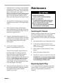
Maintenance
POTENTIAL HAZARD
• Engine could be started accidentally.
WHAT CAN HAPPEN
• Accidental starting of engine could cause
serious injury to operator or bystanders.
HOW TO AV
OID THE HAZARD
• Pull wire off spark plug before performing
any maintenance or adjustments.
Servicing
Air Cleaner
Normally, replace air cleaner after every 25 operating
hours. More frequent replacing is required when
mower is operated in dusty or dirty conditions. See
your Authorized Toro Service Dealer for replacement
parts.
1. Stop engine and pull wire off spark plug (Fig. 8).
2. Loosen screw securing air cleaner cover to
engine (Fig. 15). Tilt air cleaner cover down and
clean cover thoroughly.
3. Remove paper air cleaner filter (Fig. 15) and
discard.
4. Insert a new paper air cleaner filter.
5. Reinstall air cleaner cover and secure with screw.
IMPORTANT: Do not operate engine without
air cleaner element otherwise extreme engine
wear and damage will likely result.
Replacing
Spark Plug
Use a Champion RJ19LM spark plug or equivalent.
Correct air gap is 0.76 mm (0.030”). Remove plug
after every 25 operating hours and check its
condition.
La page est en cours de chargement...
La page est en cours de chargement...
La page est en cours de chargement...
La page est en cours de chargement...
La page est en cours de chargement...
La page est en cours de chargement...
La page est en cours de chargement...
La page est en cours de chargement...
La page est en cours de chargement...
La page est en cours de chargement...
La page est en cours de chargement...
La page est en cours de chargement...
La page est en cours de chargement...
La page est en cours de chargement...
La page est en cours de chargement...
La page est en cours de chargement...
La page est en cours de chargement...
La page est en cours de chargement...
La page est en cours de chargement...
La page est en cours de chargement...
La page est en cours de chargement...
La page est en cours de chargement...
La page est en cours de chargement...
La page est en cours de chargement...
-
 1
1
-
 2
2
-
 3
3
-
 4
4
-
 5
5
-
 6
6
-
 7
7
-
 8
8
-
 9
9
-
 10
10
-
 11
11
-
 12
12
-
 13
13
-
 14
14
-
 15
15
-
 16
16
-
 17
17
-
 18
18
-
 19
19
-
 20
20
-
 21
21
-
 22
22
-
 23
23
-
 24
24
-
 25
25
-
 26
26
-
 27
27
-
 28
28
-
 29
29
-
 30
30
-
 31
31
-
 32
32
-
 33
33
-
 34
34
-
 35
35
-
 36
36
-
 37
37
-
 38
38
-
 39
39
-
 40
40
-
 41
41
-
 42
42
-
 43
43
-
 44
44


Toro 48cm Recycler/Rear Bagging Lawnmower Manuel utilisateur
- Catégorie
- Tondeuses à gazon
- Taper
- Manuel utilisateur
dans d''autres langues
Documents connexes
-
Toro 21" Recycler II Super Pro Manuel utilisateur
-
-
Toro 48cm Recycler/Rear Bagging Lawnmower Manuel utilisateur
-
Toro Heavy-Duty Proline 53 cm Professional Walk Behind Mower 22291 Manuel utilisateur
-
-
Toro Super Recycler Lawnmower Manuel utilisateur
-
Toro Lawnmower Manuel utilisateur
-
-
-