Samsung SCC-C7437 Manuel utilisateur
- Catégorie
- Des caméras de sécurité
- Taper
- Manuel utilisateur
Ce manuel convient également à

SCC-C7437N
imagine the possibilities
Thanks you for purchasing this Samsung product.
To receive a more complete service, please visit
our website
www.samsungsecurity.com
(Outdoor Type)
Smart Dome Camera
User Manual
00955F-NA_SCC-C7437N-ENG-1.indd 1 2009-10-19 8:24:23

2_ overview
overview
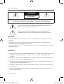
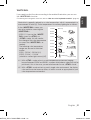
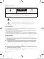
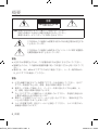
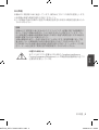
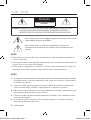
CAUTION
RISK OF ELECTRIC SHOCK.
DO NOT OPEN
CAUTION: TO REDUCE THE RISK OF ELECTRIC SHOCK, DO NOT REMOVE COVER (OR BACK) NO USER
SERVICEABLE PARTS INSIDE. REFER SERVICING TO QUALIFIED SERVICE PERSONNEL.
This symbol indicates that dangerous voltage consisting a risk of
electric shock is present within this unit.
This symbol indicates that there are important operating and
maintenance instructions in the literature accompanying this unit.
WARNING
To reduce the risk of fire or electric shock, do not expose this appliance to rain or
moisture.
To prevent injury, this apparatus must be securely attached to the floor/wall in
accordance with the installation instructions.
Use only the 24V, 60Hz AC adaptor for power supply. Use an adaptor over 3A when
the heater works.
WARNING
Be sure to use only the standard adapter that is specified in the specification sheet.
Using any other adapter could cause fire, electrical shock, or damage to the
product.
Incorrectly connecting the power supply or replacing battery may cause explosion,
fire, electric shock, or damage to the product.
Do not connect multiple cameras to a single adapter. Exceeding the capacity may
cause abnormal heat generation or fire.
Securely plug the power cord into the power receptacle. Insecure connection may
cause fire.
When installing the camera, fasten it securely and firmly. The fall of camera may
cause personal injury.
1.
2.
3.
4.
5.
00955F-NA_SCC-C7437N-ENG-1.indd 2 2009-10-19 8:24:23

English _3
English
Do not place conductive objects (e.g. screwdrivers, coins, metal parts, etc.) or
containers filled with water on top of the camera. Doing so may cause personal
injury due to fire, electric shock, or falling objects.
Do not install the unit in humid, dusty, or sooty locations. Doing so may cause fire
or electric shock.
If any unusual smells or smoke come from the unit, stop using the product. In such
case, immediately disconnect the power source and contact the service center.
Continued use in such a condition may cause fire or electric shock.
If this product fails to operate normally, contact the nearest service center. Never
disassemble or modify this product in any way. (SAMSUNG is not liable for
problems caused by unauthorized modifications or attempted repair.)
When cleaning, do not spray water directly onto parts of the product. Doing so may
cause fire or electric shock
Do not expose the product to the direct airflow from an air conditioner.
Otherwise, it may cause moisture condensation inside the Clear Dome due to
temperature difference between internal and external of the dome camera.
If you install this product in a low-temp area such as inside a cold store, you must
seal up the wiring pipe with silicon, so that the external air can not flow inside the
housing.
Otherwise, external high, humid air may flow inside the housing, pooling moisture
or vapor inside the product due to a difference between internal and external
temperature.
6.
7.
8.
9.
10.
11.
12.
00955F-NA_SCC-C7437N-ENG-1.indd 3 2009-10-19 8:24:23

overview
4_ overview
CAUTION
Do not drop objects on the product or apply strong blows to it. Keep away from a
location subject to excessive vibration or magnetic interference.
Do not install in a location subject to high temperature (over 50°C), low temperature
(below -50°C), or high humidity. Doing so may cause fire or electric shock.
If you want to relocate the already installed product, be sure to turn off the power
and then move or reinstall it.
Remove the power plug from the outlet when there is a lighting storm. Neglecting
to do so may cause fire or damage to the product.
Keep out of direct sunlight and heat radiation sources. It may cause fire.
Install it in a place with good ventilation.
Avoid aiming the camera directly towards extremely bright objects such as sun, as
this may damage the CCD image sensor.
Apparatus shall not be exposed to dripping or splashing and no objects filled with
liquids, such as vases, shall be placed on the apparatus.
The Mains plug is used as a disconnect device and shall stay readily operable at
any time.
When the unit is stored in high humidity environment, moisture may occur inside
the cover dome of the Housing. Before installation, please open the cover dome
and wipe off all moisture with a soft dry cloth.
1.
2.
3.
4.
5.
6.
7.
8.
9.
10.
00955F-NA_SCC-C7437N-ENG-1.indd 4 2009-10-19 8:24:23

English _5
English
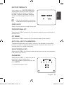
FCC STATEMENT
This device complies with part 15 of the FCC Rules. Operation is subject to the following
two conditions :
1) This device may not cause harmful interference, and
2) This device must accept any interference received including interference that may
cause undesired operation.
Caution
This equipment has been tested and found to comply with the limits for a Class A
digital device, pursuant to part 15 of FCC Rules. These limits are designed to provide
reasonable protection against harmful interference when the equipment is operated
in a commercial environment.
This equipment generates, uses, and can radiate radio frequency energy and, if not
installed and used in accordance with the instruction manual, may cause harmful
interference to radio communications. Operation of this equipment in a residential
area is likely to cause harmful interference in which case the user will be required to
correct the interference at his own expense.
IC Compliance Notice
This Class A digital apparatus meets all requirements of the Canadian
Interference.-Causing Equipment Regulations of ICES-003.
00955F-NA_SCC-C7437N-ENG-1.indd 5 2009-10-19 8:24:23

overview
6_ overview
IMPORTANT SAFETY INSTRUCTIONS
Read these instructions.
Keep these instructions.
Heed all warnings.
Follow all instructions.
Do not use this apparatus near water.
Clean only with dry cloth.
Do not block any ventilation openings. Install in accordance with the manufacturer’s
instructions.
Do not install near any heat sources such as radiators, heat registers, or other
apparatus (including amplifiers) that produce heat.
Do not defeat the safety purpose of the polarized or grounding-type plug.
A polarized plug has two blades with one wider than the other. A grounding type
plug has two blades and a third grounding prong. The wide blade or the third prong
is provided for your safety. If the provided plug does not fit into your outlet, consult
an electrician for replacement of the obsolete outlet.
Protect the power cord from being walked on or pinched particularly at plugs,
convenience receptacles, and the point where they exit from the apparatus.
Only use attachments/accessories specified by the manufacturer.
Use only with the cart, stand, tripod, bracket, or table specified
by the manufacturer, or sold with the apparatus. When a
cart is used, use caution when moving the cart/apparatus
combination to avoid injury from tip-over.
Unplug this apparatus during lightning storms or when unused
for long periods of time.
Refer all servicing to qualified service personnel. Servicing is required when the
apparatus has been damaged in any way, such as powersupply cord or plug is
damaged, liquid has been spilled or objects have fallen into the apparatus, the
apparatus has been exposed to rain or moisture, does not operate normally, or has
been dropped.
Apparatus shall not be exposed to dripping or splashing and no objects
filled with liquids, such as vases, shall be placed on the apparatus
1.
2.
3.
4.
5.
6.
7.
8.
9.
10.
11.
12.
13.
14.
00955F-NA_SCC-C7437N-ENG-1.indd 6 2009-10-19 8:24:23

English _7
English
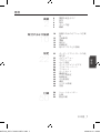
CONTENTS
OVERVIEW
2
6 Important Safety Instructions
7 Contents
8 Features
8 What’s Included
9 At a Glance
INSTALLATION &
CONNECTION
10
10 Optional Accessories for
Installation
12 Precautions
12 Preparation
13 Installation
16 Initial Setup
19 Connecting with other Device
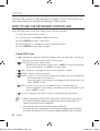
SETUP
22
22 How to use the Keyboard
Controller
23 Main Menu
24 Profile
26 Camera Set
35 Intelligent Video
36 Privacy Zone
37 Preset
39 Auto Set
43 Zone Set
44 Alarm Set
46 Clock Set
46 Other Set
48 Communication
48 System Info
49 Language
APPENDIX
50
50 Shortcut Keys
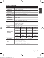
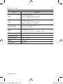
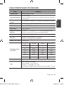
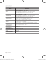
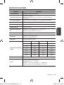
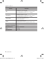
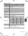
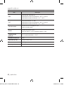
51 Specifications
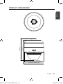
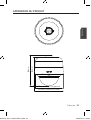
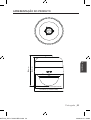
53 Product Appearance
00955F-NA_SCC-C7437N-ENG-1.indd 7 2009-10-19 8:24:23

overview
8_ overview
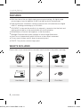
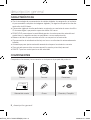
FEATURES
With the state-of-the-art digital signal processing technology, full digital image
processing and special algorithm of 600-line high resolution implemented
High performance surveillance camera, equipped with x34 zoom lens and digital
zoom IC, enabling monitoring up to 544 times
DAY/NIGHT to improve the sensitivity by automatic conversion into the black and
white mode at night or in the environment with low illumination
White Balance to control the brightness to the illumination
Backlight Compensation under spotlight or utmost bright illumination
Auto Focus to automatically adjust the focus to the subject movement
Privacy zone to hide a specific area for personal privacy
PAN/TILT for precise control at high speed
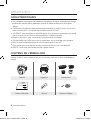
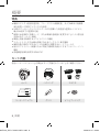
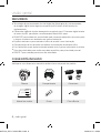
WHAT’S INCLUDED
Please check if your camera and accessories are all included in the product package.
Camera Housing Connectors
User Manual Grease Pin & Bush
00955F-NA_SCC-C7437N-ENG-1.indd 8 2009-10-19 8:24:26

English _9
English
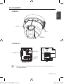
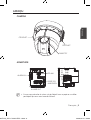
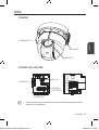
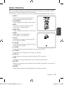
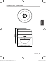
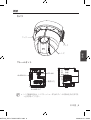
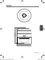
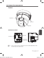
AT A GLANCE
CAMERA
FRAME SET
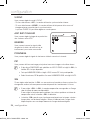
Wipe out a dirty surface of the lens softly with a lens tissue or cloth to which you
have applied ethanol.
M
LENS
HOOK
HOOK
ALARM IN
ALARM OUT
RS-485
POWER
INPUT
00955F-NA_SCC-C7437N-ENG-1.indd 9 2009-10-19 8:24:31

10_ installation & connection
installation & connection
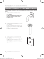
OPTIONAL ACCESSORIES FOR INSTALLATION
For your easier installation, you can purchase appropriate optional accessories available.
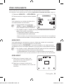
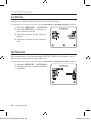
WALL MOUNT ADAPTOR (SCX-300WM)
This is a wall mount adaptor, used for wall-
mounted installation of SMART DOME
CAMEA units.
CEILING MOUNT ADAPTOR (SCX-300CM)
This is a ceiling mount adaptor, used for
installation of SMART DOME CAMEA units on
a concrete ceiling.
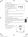
POLE MOUNT ADAPTOR (SCX-300PM)
This is an adaptor for WALL MOUNT
ADAPTOR (SCX-300WM) installation on a
pole whose diameter is bigger than 80mm.
1.
2.
3.
00955F-NA_SCC-C7437N-ENG-1.indd 10 2009-10-19 8:24:33

English _11
English
CORNER MOUNT ADAPTOR (SCX-300KM)
This is an adaptor for WALL MOUNT
ADAPTOR (SCX-300WM) installation on the
corner of wall joint.
PARAPET (LONG) MOUNT (SCX-300LM)
This is a mounting kit used for installation of
SMART DOME CAMEA units on a parapet.
4.
5.
00955F-NA_SCC-C7437N-ENG-1.indd 11 2009-10-19 8:24:33

installation & connection
12_ installation & connection
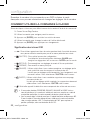
PRECAUTIONS
Select an installation spot which can endure more than 4 times of the product
weight.
When installing, prevent peoples approaching to avoid personal injury.
Move valuables to a safer place before installing.
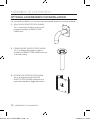
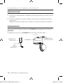
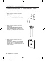
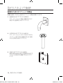
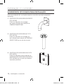
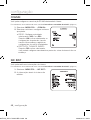
PREPARATION
Run all the external cables through the bracket adaptor’s PIPE or MOUNT hole.
Wrap around the HOUSING’s screw hole with the Teflon Tape.
1.
2.
PIPE OR
MOUNT
1.5" PT
EXTERNAL
CABLE
1.5" PT
TEFLON TAPE
HOUSING
00955F-NA_SCC-C7437N-ENG-1.indd 12 2009-10-19 8:24:34

English _13
English
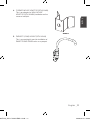
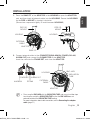
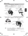
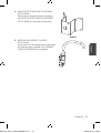
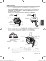
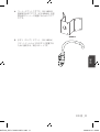
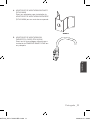
INSTALLATION
Press the SNAP FIT of the ADAPTOR in the HOUSING to open the ADAPTOR
part, and then insert all external cables into the HOUSING. Secure the HOUSING
on the PIPE or MOUNT by turning it clockwise.
(Secure two components tightly, to avoid loosened HOUSING.)
Connect external cables to the CONNECTORS(ALARM IN, POWER, RS-485,
ALARM OUT) and connect the CONNECTOR to the ADAPTOR.
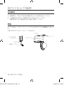
Insert the cable into the FRAME SET, and close the ADAPTOR.
Then, wrap the BNC JACK with the INSULATION TUBE, and use an insulation tape
to seal up the end of the INSULATION TUBE so that the BNC JACK does not
protrude outside of the INSULATION TUBE coating.
For more information about cable connection, refer to Connecting the adaptor
cable. (page 21)
1.
2.
M
PIPE OR
MOUNT
HOUSING
EXTERNAL
CABLE
ADAPTOR
SNAP-FIT
PIPE OR
MOUNT
HOUSING
HOUSING
EXTERNAL
CABLE
ADAPTOR
BNC JACK
INSULATION
TUBE
ALARM OUT
ALARM IN
RS-485
POWER INPUT
00955F-NA_SCC-C7437N-ENG-1.indd 13 2009-10-19 8:24:38

installation & connection
14_ installation & connection
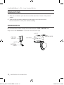
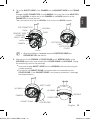
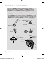
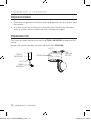
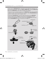
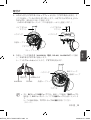
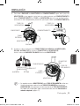
Note that BUSHINGs are provided for outdoor installations where exposed to a
moisture condition through the PIPE or MOUNT, install the HOUSING using the
BUSHING to prevent moisture entering.
- Apply grease of proper dose on the BUSHING before assembling, and run
cables through each hole of the bushings. Use PINS to stop up empty holes
having no cable running.
- Assemble the
BUSHING to the top side of HOUSING’s inside as shown in the
diagram below. At the moment, apply pressure evenly on the BUSHING to
secure it tightly to the HOUSING as shown in the diagram.
BUSH
BUSH
ETC CABLE
POWER
(24V) CABLE
BNC CABLE
BUSH
BUSH
PIN
BUSH
HOUSING
PIPE OR
MOUNT
BUSH
HOUSING
00955F-NA_SCC-C7437N-ENG-1.indd 14 2009-10-19 8:24:42

English _15
English
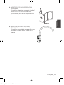
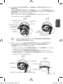
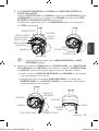
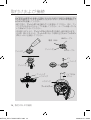
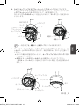
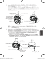
Tie up the SAFETY WIRE of the CAMERA on the BRACKET WIRE of the FRAME
SET.
Arrange the 22P CONNECTOR of the CAMERA in line with that of the ADAPTOR,
push the HOOKs on either end of the CAMERA in the RACK direction of the
FRAME SET to secure the two.
Then, ensure that all of the two HOOKs clicks to fix to the RACK properly.
When the installation is completed, remove the PROTECTIVE COVER and
PRETOECTIVE TAPE from the lens.
Align each of the 3 SCREWS of COVER DOME and 3 SCREW HOLEs of the
HOUSING respectively, and assemble the COVER DOME and HOUSING. During
the assembling, note on the followings.
Insert and arrange SAFETY WIRE into the HOUSING while not disturbing the
camera operation.
Ensure that the GASKET DOME component does not separate from the
COVER DOME
. (If the GASKET DOME is not properly assembled, it damages
the waterproofness.)
3.
M
4.
22P CONNECTOR
HOUSING
RACK
RACK
BRACKET WIRE
FRAME SET
SAFETY WIRE
HOOK
HOOK
CAMERA
PROTECTIVE
COVER
PROTECTIVE
TAPE
SCREWS
HOUSING
COVER DOME
COVER DOME
GASKET DOME
CAMERA
HOUSING
SAFETY WIRE
00955F-NA_SCC-C7437N-ENG-1.indd 15 2009-10-19 8:24:45

installation & connection
16_ installation & connection
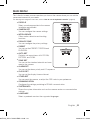
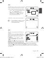
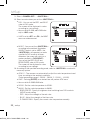
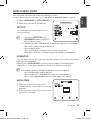
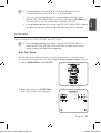
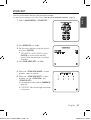
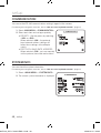
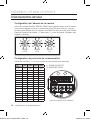
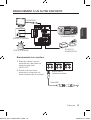
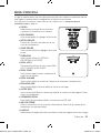
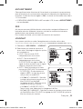
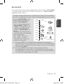
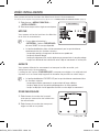
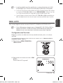
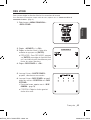
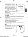
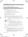
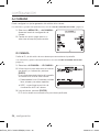
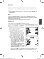
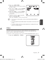
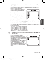
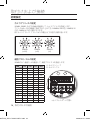
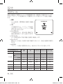
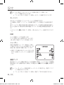
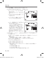
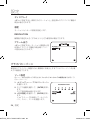
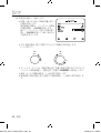
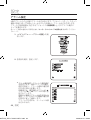
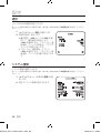
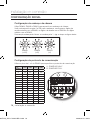
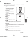
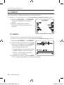
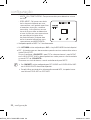
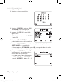
INITIAL SETUP
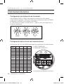
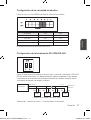
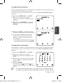
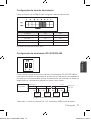
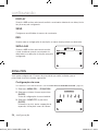
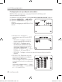
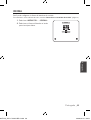
Camera Address Setup
Use SW606, SW605, and SW604 to specify the camera address.
You can specify between 0 and 255 for the address, where the hundreds digit is
with SW606, the tens digit with SW605, and the ones digit with SW604.
ex) Camera address: If the address is 1, follow the steps in the figure below.
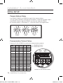
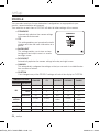
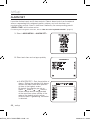
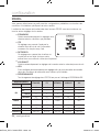
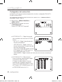
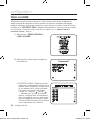
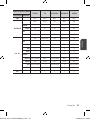
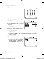
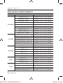
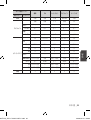
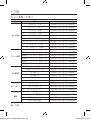
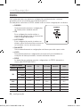
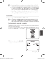
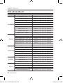
Communication Protocol Setup
Use pins #1~#4 of SW603 to specify the communication protocol.
PIN
Comp
PIN1 PIN2 PIN3 PIN4
A OFF OFF OFF OFF
B ON OFF OFF OFF
C OFF ON OFF OFF
D ON ON OFF OFF
E OFF OFF ON OFF
F ON OFF ON OFF
G OFF ON ON OFF
H ON ON ON OFF
I OFF OFF OFF ON
J ON OFF OFF ON
K OFF ON OFF ON
L ON ON OFF ON
M OFF OFF ON ON
N ON OFF ON ON
O OFF ON ON ON
P ON ON ON ON
A : SAMSUNG HALF
B : SAMSUNG FULL
<Bottom of the camera holder>
SW606
(x100)
SW605
(x10)
SW604
(x1)
00955F-NA_SCC-C7437N-ENG-1.indd 16 2009-10-19 8:24:48

English _17
English
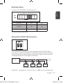
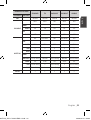
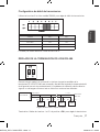
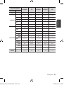
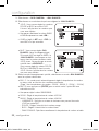
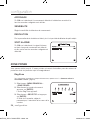
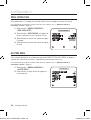
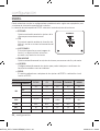
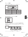
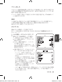
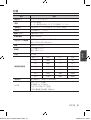
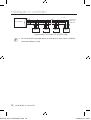
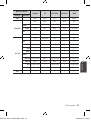
Baud Rate Setup
Use pins #5, #6 of SW603 to set the baud rate.
BAUD RATE PIN 5 PIN 6
4800 BPS ON ON
9600 BPS OFF ON
19200 BPS ON OFF
38400 BPS OFF OFF
The factory default is 9600 BPS.
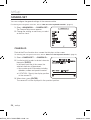
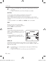
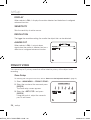
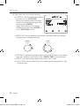
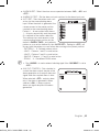
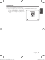
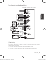
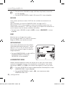
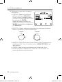
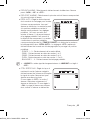
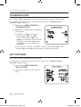
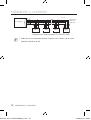
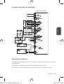
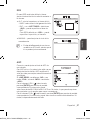
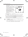
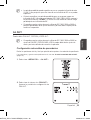
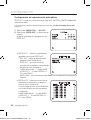
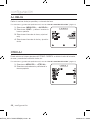
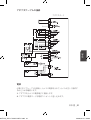
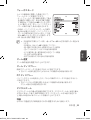
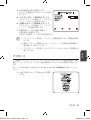
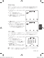
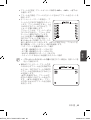
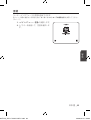
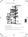
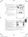
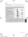
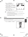
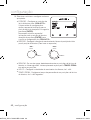
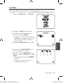
Setting RS-422A/RS-485 Termination
As it is shown in the structure map, when Controller and RS-422A/RS-485 is
connected, it should be terminated according to the Cable feature of impedance
on the each end of the transmitting line to transfer the signals in long distance by
controlling the reflection of the signals to the lowest.
Termination : Using numbers 1 and 2 PIN, turn to <ON> and it will be terminated.
Controller
Termination
n < 32
Termination
SW1-ON
CAM n
CAM n-1
CAM 2
CAM 1
TX+(DATA+)
TX-(DATA-)
RX-
RX+
RX+ RX- RX+ RX- RX+ RX-
<RS-485 Half Duplex Organization>
00955F-NA_SCC-C7437N-ENG-1.indd 17 2009-10-19 8:24:49

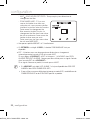
installation & connection
18_ installation & connection
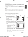
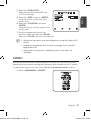
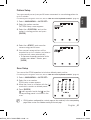
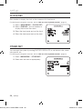
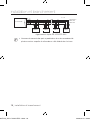
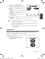
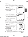
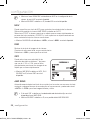
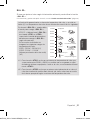
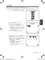
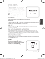
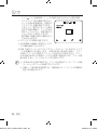
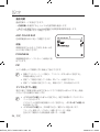
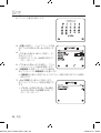
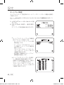
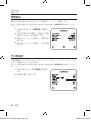
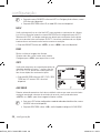
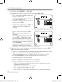
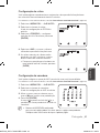
A communication error may occur if you connect multiple cameras that are assigned
the same address in the network.
M
Controller
Termination
n < 32
Termination
SW1-ON
SW2-ON
CAM n
CAM n-1
CAM 2CAM 1
<RS-422A/RS-485 Full Duplex Organization>
00955F-NA_SCC-C7437N-ENG-1.indd 18 2009-10-19 8:24:49

English _19
English
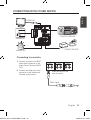
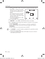
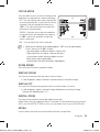
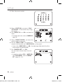
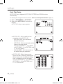
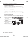
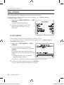
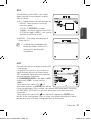
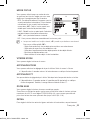
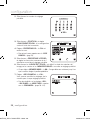
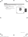
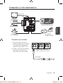
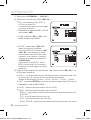
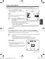
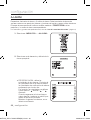
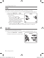
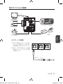
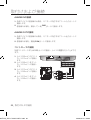
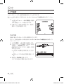
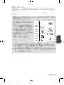
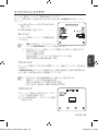
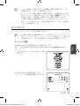
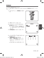
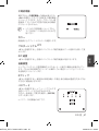
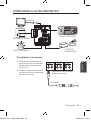
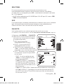
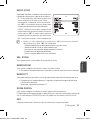
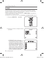
CONNECTING WITH OTHER DEVICE
Connecting to a monitor
Connect one end of the BNC
video cable connector to the
Video Output Terminal (VIDEO
OUT).
Connect the other end of the
connector to the Video Input
Terminal of the monitor.
1.
2.
Video terminal on the
rear of monitor
BNC Cable
MONITOR
ALARM IN
POWER SOURCE
ALARM OUT
CONTROLLER/DVR
00955F-NA_SCC-C7437N-ENG-1.indd 19 2009-10-19 8:24:50

installation & connection
20_ installation & connection
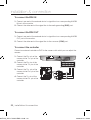
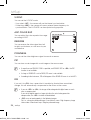
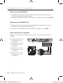
To connect ALARM IN
Connect one end of the external device's signal line to a corresponding ALARM
IN port of the monitor.
Connect the other end of the signal line to the earth-grounding [GND] port.
To connect ALARM OUT
Connect one end of the external device's signal line to a corresponding ALARM
OUT port of the monitor.
Connect the other end of the signal line to the common [COM] port.
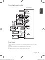
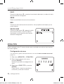
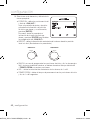
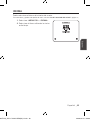
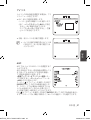
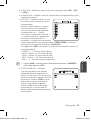
To connect the controller
Connect an external controller or DVR to the camera, with which you can adjust the
camera.
Connect the Rx+ pin of the
camera to the Tx+ pin of the
controller.
Connect the Rx- pin of the
camera to the Tx- pin of the
controller.
Connect the Tx+ pin of the
camera to the Rx+ pin of the
controller.
Connect the Tx- pin of the
camera to the Rx- pin of the
controller.
1.
2.
1.
2.
1.
2.
3.
4.
TxRx
00955F-NA_SCC-C7437N-ENG-1.indd 20 2009-10-19 8:24:51
La page charge ...
La page charge ...
La page charge ...
La page charge ...
La page charge ...
La page charge ...
La page charge ...
La page charge ...
La page charge ...
La page charge ...
La page charge ...
La page charge ...
La page charge ...
La page charge ...
La page charge ...
La page charge ...
La page charge ...
La page charge ...
La page charge ...
La page charge ...
La page charge ...
La page charge ...
La page charge ...
La page charge ...
La page charge ...
La page charge ...
La page charge ...
La page charge ...
La page charge ...
La page charge ...
La page charge ...
La page charge ...
La page charge ...
La page charge ...
La page charge ...
La page charge ...
La page charge ...
La page charge ...
La page charge ...
La page charge ...
La page charge ...
La page charge ...
La page charge ...
La page charge ...
La page charge ...
La page charge ...
La page charge ...
La page charge ...
La page charge ...
La page charge ...
La page charge ...
La page charge ...
La page charge ...
La page charge ...
La page charge ...
La page charge ...
La page charge ...
La page charge ...
La page charge ...
La page charge ...
La page charge ...
La page charge ...
La page charge ...
La page charge ...
La page charge ...
La page charge ...
La page charge ...
La page charge ...
La page charge ...
La page charge ...
La page charge ...
La page charge ...
La page charge ...
La page charge ...
La page charge ...
La page charge ...
La page charge ...
La page charge ...
La page charge ...
La page charge ...
La page charge ...
La page charge ...
La page charge ...
La page charge ...
La page charge ...
La page charge ...
La page charge ...
La page charge ...
La page charge ...
La page charge ...
La page charge ...
La page charge ...
La page charge ...
La page charge ...
La page charge ...
La page charge ...
La page charge ...
La page charge ...
La page charge ...
La page charge ...
La page charge ...
La page charge ...
La page charge ...
La page charge ...
La page charge ...
La page charge ...
La page charge ...
La page charge ...
La page charge ...
La page charge ...
La page charge ...
La page charge ...
La page charge ...
La page charge ...
La page charge ...
La page charge ...
La page charge ...
La page charge ...
La page charge ...
La page charge ...
La page charge ...
La page charge ...
La page charge ...
La page charge ...
La page charge ...
La page charge ...
La page charge ...
La page charge ...
La page charge ...
La page charge ...
La page charge ...
La page charge ...
La page charge ...
La page charge ...
La page charge ...
La page charge ...
La page charge ...
La page charge ...
La page charge ...
La page charge ...
La page charge ...
La page charge ...
La page charge ...
La page charge ...
La page charge ...
La page charge ...
La page charge ...
La page charge ...
La page charge ...
La page charge ...
La page charge ...
La page charge ...
La page charge ...
La page charge ...
La page charge ...
La page charge ...
La page charge ...
La page charge ...
La page charge ...
La page charge ...
La page charge ...
La page charge ...
La page charge ...
La page charge ...
La page charge ...
La page charge ...
La page charge ...
La page charge ...
La page charge ...
La page charge ...
La page charge ...
La page charge ...
La page charge ...
La page charge ...
La page charge ...
La page charge ...
La page charge ...
La page charge ...
La page charge ...
La page charge ...
La page charge ...
La page charge ...
La page charge ...
La page charge ...
La page charge ...
La page charge ...
La page charge ...
La page charge ...
La page charge ...
La page charge ...
La page charge ...
La page charge ...
La page charge ...
La page charge ...
La page charge ...
La page charge ...
La page charge ...
La page charge ...
La page charge ...
La page charge ...
La page charge ...
La page charge ...
La page charge ...
La page charge ...
La page charge ...
La page charge ...
La page charge ...
La page charge ...
La page charge ...
La page charge ...
La page charge ...
La page charge ...
La page charge ...
La page charge ...
La page charge ...
La page charge ...
La page charge ...
La page charge ...
La page charge ...
La page charge ...
La page charge ...
La page charge ...
La page charge ...
La page charge ...
La page charge ...
La page charge ...
La page charge ...
La page charge ...
La page charge ...
La page charge ...
La page charge ...
La page charge ...
La page charge ...
La page charge ...
La page charge ...
La page charge ...
La page charge ...
La page charge ...
La page charge ...
La page charge ...
La page charge ...
La page charge ...
La page charge ...
La page charge ...
La page charge ...
La page charge ...
La page charge ...
La page charge ...
La page charge ...
La page charge ...
-
 1
1
-
 2
2
-
 3
3
-
 4
4
-
 5
5
-
 6
6
-
 7
7
-
 8
8
-
 9
9
-
 10
10
-
 11
11
-
 12
12
-
 13
13
-
 14
14
-
 15
15
-
 16
16
-
 17
17
-
 18
18
-
 19
19
-
 20
20
-
 21
21
-
 22
22
-
 23
23
-
 24
24
-
 25
25
-
 26
26
-
 27
27
-
 28
28
-
 29
29
-
 30
30
-
 31
31
-
 32
32
-
 33
33
-
 34
34
-
 35
35
-
 36
36
-
 37
37
-
 38
38
-
 39
39
-
 40
40
-
 41
41
-
 42
42
-
 43
43
-
 44
44
-
 45
45
-
 46
46
-
 47
47
-
 48
48
-
 49
49
-
 50
50
-
 51
51
-
 52
52
-
 53
53
-
 54
54
-
 55
55
-
 56
56
-
 57
57
-
 58
58
-
 59
59
-
 60
60
-
 61
61
-
 62
62
-
 63
63
-
 64
64
-
 65
65
-
 66
66
-
 67
67
-
 68
68
-
 69
69
-
 70
70
-
 71
71
-
 72
72
-
 73
73
-
 74
74
-
 75
75
-
 76
76
-
 77
77
-
 78
78
-
 79
79
-
 80
80
-
 81
81
-
 82
82
-
 83
83
-
 84
84
-
 85
85
-
 86
86
-
 87
87
-
 88
88
-
 89
89
-
 90
90
-
 91
91
-
 92
92
-
 93
93
-
 94
94
-
 95
95
-
 96
96
-
 97
97
-
 98
98
-
 99
99
-
 100
100
-
 101
101
-
 102
102
-
 103
103
-
 104
104
-
 105
105
-
 106
106
-
 107
107
-
 108
108
-
 109
109
-
 110
110
-
 111
111
-
 112
112
-
 113
113
-
 114
114
-
 115
115
-
 116
116
-
 117
117
-
 118
118
-
 119
119
-
 120
120
-
 121
121
-
 122
122
-
 123
123
-
 124
124
-
 125
125
-
 126
126
-
 127
127
-
 128
128
-
 129
129
-
 130
130
-
 131
131
-
 132
132
-
 133
133
-
 134
134
-
 135
135
-
 136
136
-
 137
137
-
 138
138
-
 139
139
-
 140
140
-
 141
141
-
 142
142
-
 143
143
-
 144
144
-
 145
145
-
 146
146
-
 147
147
-
 148
148
-
 149
149
-
 150
150
-
 151
151
-
 152
152
-
 153
153
-
 154
154
-
 155
155
-
 156
156
-
 157
157
-
 158
158
-
 159
159
-
 160
160
-
 161
161
-
 162
162
-
 163
163
-
 164
164
-
 165
165
-
 166
166
-
 167
167
-
 168
168
-
 169
169
-
 170
170
-
 171
171
-
 172
172
-
 173
173
-
 174
174
-
 175
175
-
 176
176
-
 177
177
-
 178
178
-
 179
179
-
 180
180
-
 181
181
-
 182
182
-
 183
183
-
 184
184
-
 185
185
-
 186
186
-
 187
187
-
 188
188
-
 189
189
-
 190
190
-
 191
191
-
 192
192
-
 193
193
-
 194
194
-
 195
195
-
 196
196
-
 197
197
-
 198
198
-
 199
199
-
 200
200
-
 201
201
-
 202
202
-
 203
203
-
 204
204
-
 205
205
-
 206
206
-
 207
207
-
 208
208
-
 209
209
-
 210
210
-
 211
211
-
 212
212
-
 213
213
-
 214
214
-
 215
215
-
 216
216
-
 217
217
-
 218
218
-
 219
219
-
 220
220
-
 221
221
-
 222
222
-
 223
223
-
 224
224
-
 225
225
-
 226
226
-
 227
227
-
 228
228
-
 229
229
-
 230
230
-
 231
231
-
 232
232
-
 233
233
-
 234
234
-
 235
235
-
 236
236
-
 237
237
-
 238
238
-
 239
239
-
 240
240
-
 241
241
-
 242
242
-
 243
243
-
 244
244
-
 245
245
-
 246
246
-
 247
247
-
 248
248
-
 249
249
-
 250
250
-
 251
251
-
 252
252
-
 253
253
-
 254
254
-
 255
255
-
 256
256
-
 257
257
-
 258
258
-
 259
259
-
 260
260
-
 261
261
-
 262
262
-
 263
263
-
 264
264
-
 265
265
-
 266
266
-
 267
267
-
 268
268
-
 269
269
-
 270
270


Samsung SCC-C7437 Manuel utilisateur
- Catégorie
- Des caméras de sécurité
- Taper
- Manuel utilisateur
- Ce manuel convient également à
dans d''autres langues
- español: Samsung SCC-C7437 Manual de usuario
- português: Samsung SCC-C7437 Manual do usuário
- 日本語: Samsung SCC-C7437 ユーザーマニュアル
Documents connexes
-
Samsung SCC-C6437P Manuel utilisateur
-
Samsung SCC-C6453 Le manuel du propriétaire
-
-
-
-
Samsung SCC-C7325 Manuel utilisateur
-
Samsung SCX-RD100 Le manuel du propriétaire
-
-
-
Autres documents
-
i3 International Di721 Manuel utilisateur
-
Swann Pro-Series Manuel utilisateur
-
Sony SSC-CD73VT Manuel utilisateur
-
Panasonic WV-CW974 Manuel utilisateur
-
Veho UW-29 Manuel utilisateur
-
Sony IPELA RZ25P Manuel utilisateur
-
-