Tempco Photohelic 3006 Installation And Operating Instructions Manual
- Taper
- Installation And Operating Instructions Manual

TEMPCO s.a. 4e ave. N°114, Z.I. des Hauts Sarts, B-4040 Herstal, Belgique. T:(32)04-2649458, F:(32)04-2649476, www.tempco.be, [email protected]
Les photos et caractéristiques présentés dans ce catalogue sont données à titre indicatif et ne sont pas contractuelles.
3.A.01.450-E-100910 page 1/7
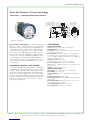
The Photohelic®Switch/Gage is a very versatile, precise
pressure switch combined with the time-proven
Magnehelic®pressure gage. Models are available with one
or two phototransistor actuated relays. Gage reading is
unaffected by switch operation. Easy to adjust set points
have knob controls. Applied pressure and switch set points
are fully visible at all times. Deadband is one pointer width -
less than 1% of full scale. Double-pole double-throw relays
can be easily interlocked to provide variable deadband con-
trol. For positive, negative or differential pressure only on
3600S models. Full scale ranges available from 0-.25 in w.c.
to 0-6000 psig.
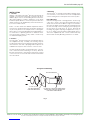
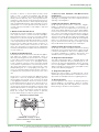
PHOTOHELIC®SENSING - HOW IT WORKS
In a typical control application, the Photohelic®switch/gage
controls between high and low pressure set points. When
pressure changes, reaching either set point pressure, the
beam from an LED to the limiting phototransistor will be cut
off by the helix-driven light shield. The resulting signal
change is electronically amplified to actuate its DPDT slave
relay and switching occurs. Dead band between make and
break is 1% of full scale or less - just enough to assure pos-
itive, chatter-free operation.
Series 3000 Photohelic®Pressure Switch/Gage
Specifications - Installation and Operating Instructions
SPECIFICATIONS
GAGE SPECIFICATIONS
Service: Air and non-combustible, compatible gases.
Wetted Materials: Consult Factory.
Accuracy: Photohelic®, ±2% of full scale at 70°F (21.1°C). ±3%
on -0 and ±4% on -00 models.
Pressure Limits: Photohelic®-20" Hg. to 25 psig (-0.677 to
1.72 bar). MP option; 35 psig (2.41 bar), HP option; 80 psig
(5.52 bar). 36003S – 36010S; 150 psig (10.34 bar). 36020S and
higher; 1.2 x full scale pressure.
Temperature Limits: 20 to 120°F.
(-6.67 to 48.9°C) Low temperature option available.
Process Connections: Photohelic®, 1/8˝ female NPT.
Size: Photohelic®, 4˝ (101.6 mm) dial face, 5˝ (127 mm) O.D. x 8-
1/4˝ (209.55 mm).
Weight: Photohelic®, 4 lbs. (1.81 kg).
SWITCH SPECIFICATIONS
Switch Type: Each setpoint has 2 Form C relays (DPDT).
Repeatability: ±1% of full scale.
Electrical Rating: Photohelic®, 10A @ 28 VDC, 10A @ 120,
240 VAC.
Electrical Connections: Screw Terminals.
Power Requirements: 120 VAC, 50/60 Hz; 240 VAC & 24 VAC
Power optional.
Mounting Orientation: Diaphragm in vertical position. Consult
factory for other position orientations.
Set Point Adjustment: Adjustable knobs on face.
Agency Approvals: Photohelic®UL, CSA, CE.
2-1/2 [63.50]
2-1/16 [52.39]
2 [50.80] 1-1/4
[31.75]
(4) 6-32 HOLES
EQUALLY SPACED ON
A 5-1/8 [130.18] B.C.
Ø4-47/64
[120.25] Ø5
[127.00]
Ø4 [101.60]
FACE
5-1/2 [139.70]
O.D.
MOUNTING
RING
5/8 [15.88]
5/8 [15.88] PANEL
MAX
3/16 [4.76]
3-7/8 [98.43]
5-1/8 [130.18]
6-3/8 [161.93]
(7-5/8 [193.68])
4-3/8 [111.13]
HOUSING REMOVAL
3/4 CONDUIT
CONNECTION
Ø4-3/4
[120.65]
3-7/8 SQ
[98.43]
1/8 FEMALE NPT HIGH
PRESSURE CONNECTION
1/8 FEMALE NPT LOW
PRESSURE CONNECTION
*Patent No. 3,862,416

TEMPCO s.a. 4e ave. N°114, Z.I. des Hauts Sarts, B-4040 Herstal, Belgique. T:(32)04-2649458, F:(32)04-2649476, www.tempco.be, [email protected]
Les photos et caractéristiques présentés dans ce catalogue sont données à titre indicatif et ne sont pas contractuelles.
3.A.01.450-E-100910 page 2/7
INSTALLATION
1. Location
All parts of the Dwyer Photohelic®pressure switch/gage are
ruggedly constructed and will stand a moderate amount of
vibration, physical shock, and handling. Normal care in han-
dling and installation is all that is required. In cases where
instrument panel vibration is severe, the panel should be a
spring mounted or the amplifier-relay unit mounted remote-
ly on a more stable surface.
Select a location where the ambient temperature will not
exceed 120°F. Pneumatic pressure sensing lines may be run
any necessary distance. For example, 250 foot sensing lines
will not affect accuracy but will damp the reading slightly. Do
not restrict lines. If pulsating pressure or vibration causes
excessive pointer oscillation or relay chatter, consult factory
for additional damping means.
2. Position
The Photohelic®may be mounted as an integral package or
the amplifier-load relay assembly and housing may be
mounted remotely from the indicating gage-phototransistor
unit. Extension cords with 7 pin plugs and receptacles are
available from Dwyer for interconnection of the two units.
The unit may be mounted in any desired position, scale ver-
tical or horizontal, without affecting its accuracy, but must
be rezeroed if position is changed from horizontal to vertical
or vice versa. The -0 and -00 models must be mounted with
the scale vertical.
3. Mounting
The Photohelic®is normally mounted before making electri-
cal connections, as the electrical enclosure is independent
of the mounting means and may be removed at any time.
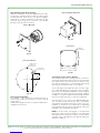
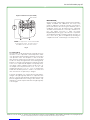
Panel Mounting
Normal mounting is flush or through panel is shown in Fig.
2. Be sure to allow 4-3/8˝ extra space behind the unit for
electrical enclosure removal. Make a single 4-13/16˝ diame-
ter hole in the panel. Insert the entire Photohelic® unit from
the front, then slip on the mounting ring and snap ring from
the rear. Seat the snap ring in its groove, back up the
mounting ring against snap ring and tighten the four (4) 2˝
No. 6-32 clamp screws provided. If behind panel space is
critical, the amplifier-relay unit can be mounted remotely.
See the Remote-Relay Mounting Instructions for details.
Fig. 2
SNAP RING GROOVE
4-13/16˝ (122 mm)
DIA. HOLE REQUIRED
FOR PANEL MOUNTING
1/8˝ MALE NPT PRESSURE CONNECTIONS.
SINGLE HIGH PRESSURE CONNECTION
FOR SERIES 36000A MODELS.
Through Panel Mounting

TEMPCO s.a. 4e ave. N°114, Z.I. des Hauts Sarts, B-4040 Herstal, Belgique. T:(32)04-2649458, F:(32)04-2649476, www.tempco.be, [email protected]
Les photos et caractéristiques présentés dans ce catalogue sont données à titre indicatif et ne sont pas contractuelles.
3.A.01.450-E-100910 page 3/7
Gage Mounting with Relays Remote
Where it is desirable to mount the amplifier-relay unit sepa-
rate from the gage-phototransistor unit, the gage may be
mounted either as shown in Fig. 2 (except less amplifier-
relay portion) or surface mounted as shown in Fig. 3A. Use
the layout shown in Fig. 3B to locate holes. The complete
package cannot be surface mounted.
Remote Relays Mounting
The amplifier - relay unit may be mounted remotely as
shown in Fig. 4A. Use the hole layout as shown in Fig. 4B
for this option.
Additional mounting information for special requirements is
available from the factory.
4. Pneumatic Connections & Zeroing
After installation but before making pressure connections,
set the indicating pointer exactly on the zero mark, using the
zero adjust screw located at the bottom of the front cover.
Note that this adjustment can only be made with the high
and low pressure taps both open to atmosphere.
Connect the high and low pressure taps to positive, nega-
tive, or differential pressure sensing points. Use 1/4˝ diame-
ter metal or other instrument tubing and 1/8˝ NPT adaptors
at the Dwyer Photohelic®pressure switch gage. Adaptors
for rubber or soft plastic tubing are furnished with the instru-
ment for use where this type of connection is preferred.
If the Photohelic®is not used to sense differential pressure,
one of the pressure taps must be left open to atmosphere.
This will allow the reference pressure to enter. In this case,
installation of a Dwyer No. A-331 Filter Plug or similar fitting
in the reference pressure tap is recommended to reduce the
possibility of dust entering the instrument.
NOTE: If the Photohelic®switch/gage is over pressured,
pointer may ‘jump” from full scale back to zero and remain
there until the excess pressure condition is relieved. Users
should be aware of possible false zero pressure indications
under this conditions.
Fig. 3A
Remote Amplifier-Relay Unit
4-9/32
[108.74]
5
[127.00] SQ
4-9/32
[108.74]
Ø3/16
TYP 4 PLACES
Surface Mounting
Fig. 3B
Hole Layout (Front)
1-1/8
[28.58]
1-1/8
[28.58]
THREE 3/16 DIA.
HOLES AT 120°
SURFACE MTG.
3/4 DIA. HOLE
FOR WIRE CONN.
Fig. 4A
Hole Layout
Fig. 4B

TEMPCO s.a. 4e ave. N°114, Z.I. des Hauts Sarts, B-4040 Herstal, Belgique. T:(32)04-2649458, F:(32)04-2649476, www.tempco.be, [email protected]
Les photos et caractéristiques présentés dans ce catalogue sont données à titre indicatif et ne sont pas contractuelles.
3.A.01.450-E-100910 page 4/7
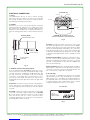
ELECTRICAL CONNECTIONS
1. Cover
The amplifier-relay unit has an easy to remove housing.
Remove the three (3) screws as shown in Fig. 5 and slide
the housing off. Make all the electrical connections before
reinstalling and refastening the housing.
2. Conduit
Electrical access to the connection box portion of the relay
housing is by bottom opening for 3/4˝ conduit. Use of flexi-
ble conduit is recommended. It should be supported from
the panel or other suitable surface to prevent the wiring sys-
tem from exerting undue strain on the instrument. See Fig.
5.
3. Terminal or Connection Board Layout
In Fig. 6,”Terminal Board”, Section A contains the connec-
tions for the load or slave relay actuated by the high or right
set-point. This relay is a double pole, double throw type. The
two top connections are normally closed, the two middle
connections are normally open, and the bottom connec-
tions are the common pair. The relay is in its normal or De-
Energized position when pressure is below the right hand
set-point.
Section D is exactly the same as Section A except that its
load or slave relay is controlled by the low or left set-point.
The De-Energized position is below the left hand pointer
set-point.
Section B contains the external connections to the holding
coil circuit for the high or right set-point relay and Section
Ccontains similar connections for the low or left set-point
relay. The function and use of these connections varies
somewhat depending on the circuit style of the instrument.
See paragraphs 5 and 6 for details.
Section E contains the power connections for the control
unit transformer primary. The transformer in turn supplies
reduced voltage power for the LED, phototransistor, ampli-
fier unit, and load relay pull in and holding coils. Connections
must always be made to this section in order to put the unit
in operation. Standard units are designed for 117 VAC input
to the transformer. Special units are also available for other
voltages.
Separate Ground Wire attachment is provided for by a
No. 6-32 screw on the mounting bracket near the conduit
opening. An additional ground wire connection is located on
the side of the gage body for use when the amplifier-relay
unit is mounted remotely.
Single Set-Point instruments are furnished with the right or
high set-point components and circuitry in place. These are
connected to Sections A and B of the terminal board. The
left or low set-point components are omitted.
4. Circuit Style
The Photohelic®is available with several factory installed
optional internal circuits. They are identified as to style by a
label shown in Fig. 7. This label is mounted prominently on
the terminal board of each instrument. The letter H denotes
a circuit in which the relay can be made to latch or remain
energized after pressure increase to its set-point.
4-3/8 [111.13]
COVER MOUNTING SCREWS
SUPPORT CONDUIT
FROM PANEL
COVER PULL
OUT
FLEXIBLE CONDUIT
Fig. 5
Mounting Details
SECTION B SECTION C
SECTION A SECTION D
SECTION E
Fig. 6
Terminal Board
CAUTION: Do not apply electrical
current to terminals in sections B and C.
CIRCUIT:
POWER SUPPLY:
CONTACT RATING:
Fig. 7
Circuit Label

TEMPCO s.a. 4e ave. N°114, Z.I. des Hauts Sarts, B-4040 Herstal, Belgique. T:(32)04-2649458, F:(32)04-2649476, www.tempco.be, [email protected]
Les photos et caractéristiques présentés dans ce catalogue sont données à titre indicatif et ne sont pas contractuelles.
3.A.01.450-E-100910 page 5/7
The letter “L” denotes a circuit in which the relay can be
made to latch or remain de-energized after pressure
decrease to its set-point. Two letters are required to fully
identify a dual set-point unit. Thus, circuit style HH, which is
standard, is a dual set-point circuit which has provisions for
latching on pressure increase to either set-point. Single relay
units are identified by the letters “SR” followed by “H” for the
standard unit or “L” for the special low latch unit. Units for
use with other than standard 117 VAC will be so indicated
on the label.
5. Dual Set Point Automatic Reset
Circuit Style HH is used for simple on-off switching applica-
tions. To place in service, connect load circuits to the appro-
priate terminals in Section A (Fig. 6) for the right set-point
and Section D for the left set-point. Note the the N.O. con-
tacts are open when the gage pressure pointer is to the left
of the set-point pointers. No connections are necessary in
Section B and C. Make external ground connections as
required and connect power to Section E for the control
unit. To use circuit style LL for automatic reset, a jumper wire
must be installed between the upper and lower terminals in
sections B and/or C.
6. Dual Set Point Manual Reset
Circuit Style HH may also be used for manual reset applica-
tions where it is desired to have maintained contact on
either relay following pressure increase above its set-point.
Load or signal connections are made to the appropriate ter-
minals in Sections A and D (as in paragraph above).
Connect terminals in Sections B and C through normally
closed switches or push buttons as shown in Fig. 8. Use of
“dry-circuit” type switches such as Dwyer Part No. A-601
with paladium, gold, etc. or rotary wiping action type con-
tacts is recommended. Make external ground connections
as required and connect power to Section E for the control
unit.
Circuit style LL is used for manual reset applications which
require that contact be maintained following pressure
decrease below the set-point. Load connections are made
to the appropriate terminals in Sections A and D. A normal-
ly open type manual reset switch such as Dwyer Part No. A-
601 is connected to the terminals in sections B and C. The
circuit must be “armed” by momentarily closing the switch
while the black pointer is to the right of the set-point. From
that point on, the circuit will latch on pressure decrease
below the set-point and remain latched on pressure
increase until manually reset with the optional switch.
7. Dual Set Point Automatic and Manual Reset
Combinations
Circuit style HH may be used with either set-point wired and
operating as in paragraph 5 and other set-point wired and
operating as in paragraph 6.
8. High Low Limit Control - Dual Set-Point
Circuit style HH may be used to control fans, dampers,
pumps, etc. between the set-points of a Photohelic®. To
accomplish this, use one set-point relay to reset the other as
shown in the wiring diagram Fig. 9. In this typical applica-
tion, the load (for instance a fan) would be connected to the
N.C. contacts of the right set-point relay, Section A (Fig. 6)/
On pressure rise to the right set-point, its relay would pull in
and hold even though pressure might then fall below that
set-point, its relay would automatically be De-Energized,
return to its normal position and in so doing, open the hold-
ing coil circuit from Section B (Fig. 6). The right set-point
relay would thus be reset and the cycle could repeat.
9. Dual Set-Point Special Purpose Circuits
Circuit Style LL may be used where manual reset following
maintained contact on pressure decrease to either set-point
is desired. Circuit Styles HL and LH are combination units.
For special combinations of features, special units, and
detailed instructions regarding their use, consult factory.
10. Single Set-Point Photohelic®
The single set-point photohelic®is furnished with the right
set-point only. Terminals in Section A and B (Fig. 6) are con-
nected to this relay. Circuit Style SRH is wired or automatic
reset as in paragraph 5. Manual reset is accomplished by
adding a normally closed reset switch or push button to the
circuit as described in paragraph 6.
11. Single Set-Point Special
Manual reset after actuation on falling pressure can be
obtained by using Circuit Style SRL. Consult the factory for
special units and detailed instructions regarding their use.
12. Placing in Service
In normal operation each relay is de-energized when the
pressure applied to the instrument is below its set-point.
Special low-latching units will ordinarily have to be reset
before placing on the line in normal operation.
RESET RESET
Fig. 8
Manual Reset with Circuit HH
CAUTION: Do not apply electrical
current to terminals in sections B and C.

TEMPCO s.a. 4e ave. N°114, Z.I. des Hauts Sarts, B-4040 Herstal, Belgique. T:(32)04-2649458, F:(32)04-2649476, www.tempco.be, [email protected]
Les photos et caractéristiques présentés dans ce catalogue sont données à titre indicatif et ne sont pas contractuelles.
3.A.01.450-E-100910 page 6/7
13. Failure Mode
The Photohelic®circuit design provides certain protection in
the event of a loss of pressure or electrical power. In either
case, both relays will de-energize, returning to their normal
“zero pressure” state. The exceptions to this are models
with center zero ranges. Because the relays on all standard
models are always energized when the indicating (black)
pointer is to the right of their respective set points, the relay
action on loss of pressure will depend on set-point position,
since either of them could be located to the left of zero. As
an example; if the left pointer were set at -2 in. w.c. and
negative pressure was -3 in. w.c., a loss of that pressure
would allow the black pointer to return to the center and
thus cause the low set-point relay to energize.
If the LED should burn out, only the left-lower relay will de-
energize. The right-high relay will react as if pressure were
above its set-point and will remain energized even though
pressure might be below that setting. In this situation, only
termination of electrical power will allow the right-high relay
to de-energize.
MAINTENANCE
Dwyer Photohelic®Switch/Gages are precision instruments,
expertly assembled and calibrated at the factory. They
require no lubrication or periodic servicing. If the interior is
protected from dust, dirt corrosive gases and fluids, years of
trouble-free service may be expected. Zero adjustment
should be checked and reset occasionally to maintain accu-
racy. Any repairs necessary to either the Dwyer
Magnehelic® pressure gage or the electronic components
should be performed by a trained instrument mechanic. In
most cases, this is best accomplished by returning the
complete Photohelic®Switch/Gage to the Dwyer factory.
117 VOLT LINE
RESET JUMPERS
1/6 HP*
117 VOLT
LOAD
Fig. 9
High-Low Limit Control (Circuit HH)
*NOTE: For larger motors, use the Photohelic®
in a maintained contact, 117 Volt Control or
Push Button Circuit of the motor starter.

TEMPCO s.a. 4e ave. N°114, Z.I. des Hauts Sarts, B-4040 Herstal, Belgique. T:(32)04-2649458, F:(32)04-2649476, www.tempco.be, [email protected]
Les photos et caractéristiques présentés dans ce catalogue sont données à titre indicatif et ne sont pas contractuelles.
3.A.01.450-E-100910 page 7/7
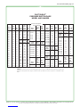
PHOTOHELIC®
PRESSURE SWITCH/GAGE
MODEL AND RANGES
Model
Number
3000-00
3000-0
3001
3002
3003
3004
3005
3006
3008
3010
3015
3020
3025
3030
3040
3050
3060
3080
3100
3150
Range,
Inches
of Water
0-.25
0-.50
0-1.0
0-2.0
0-3.0
0-4.0
0-5.0
0-6.0
0-8.0
0-10
0-15
0-20
0-25
0-30
0-40
0-50
0-60
0-80
0-100
0-150
Minor
Div.
.005
.01
.02
.05
.10
.10
.10
.20
.20
.20
.50
.50
.50
1.0
1.0
1.0
2.0
2.0
2.0
5.0
Model
Number
3300-0
3301
3302
3304
3310
3320
3330
Model
Number
3201
3202
3203
3204
3205
3210
3215
3220
3230
36003S
36006S
36010S
36020S
36030S
36060S
36100S
36300S
36600S
Range,
Zero
Center
Inches
of Water
.25-0-.25
.5-0-.5
1-0-1
2-0-2
5-0-5
10-0-10
15-0-15
Range
PSIG
0-1
0-2
0-3
0-4
0-5
0-10
0-15
0-20
0-30
0-30
0-60
0-100
0-200
0-300
0-600
0-1000
0-3000
0-6000
Minor
Div.
.01
.02
.05
.10
.20
.50
1.0
Minor
Div.
PSIG
.02
.05
.10
.10
.10
.20
.50
.50
1.0
1.0
2.0
2.0
5.0
10
20
20
100
200
Model
Number
3000-00AV
3000-0AV
3001-AV
3002-AV
3010-AV
Ranges,
Inches of
Water
0-.25
0-50
0-1.0
0-2.0
0-10
Range,
Air
Velocity
FPM
300-2000
500-2800
500-4000
1000-5600
2000-12500
Model
Number
3000-6MM
3000-10MM
3000-25MM
3000-50MM
3000-80MM
3000-100MM
Range,
MM of
Water
0-6
0-10
0-25
0-50
0-80
0-100
Minor Div.
MM
.20
.50
.50
1.0
2.0
2.0
Model
Number
3300-20MM
Range,
Zero
Center
MM
of Water
10-0-10
Minor
Div.
MM
.50
Model
Number
3000-15CM
3000-20CM
3000-25CM
3000-50CM
3000-80CM
3000-100CM
3000-150CM
3000-200CM
3000-250CM
3000-300CM
Range
CM of
Water
0-15
0-20
0-25
0-50
0-80
0-100
0-150
0-200
0-250
0-300
Minor
Div.
CM
.50
.50
.50
1.0
2.0
2.0
5.0
5.0
5.0
10.0
Model
Number
3300-4CM
3300-10CM
3300-30CM
Range,
Zero
Center
Cm of
Water
2-0-2
5-0-5
15-0-15
Minor
Div.
CM
.10
.20
1.0
Model
Number
3000-60Pa
3000-125Pa
3000-250Pa
3000-500Pa
3000-750Pa
Range,
Pascals
0-60
0-125
0-250
0-500
0-750
Minor
Div.
Pascals
2.0
5.0
5.0
10.0
25.0
Model
Number
3300-250Pa
3300-500Pa
Range,
Zero
Center
Pascals
125-0-125
250-0-250
Minor Div.
Pascals
125-0-125
250-0-250
Range
Kilo-
Pascals
0-1.0
0-1.5
0-2.0
0-3.0
0-4.0
0-5.0
0-8.0
0-10
0-15
0-20
0-25
0-30
Model
Number
3000-1kPa
3000-1.5kPa
3000-2kPa
3000-3kPa
3000-4kPa
3000-5kPa
3000-8kPa
3000-10kPa
3000-15kPa
3000-20kPa
3000-25kPa
3000-30kPa
Minor Div.
Kilo-
Pascals
.02
.05
.05
.10
.10
.10
.20
.20
.50
.50
.50
1.0
Model
Number
3300-1kPa
3300-3kPa
Range,
Zero
Center
Kilo-
pascals
.5-0-.5
1.5-0-1.5
Minor
Div.
Kilo-
pascals
.02
.10
Dual Scale Air Velocity Units
(for use with pitot tube)
*NOTE: The Photohelic®pressure switch/gage may be used in an Under writers Laboratories approved
industrial control panel if the usage conforms to UL specifications for the acceptance of unlisted compo-
nents.
-
 1
1
-
 2
2
-
 3
3
-
 4
4
-
 5
5
-
 6
6
-
 7
7


Tempco Photohelic 3006 Installation And Operating Instructions Manual
- Taper
- Installation And Operating Instructions Manual
dans d''autres langues
- English: Tempco Photohelic 3006
Autres documents
-
Blue Sea Systems 7532 Manuel utilisateur
-
Dwyer Series V4 Manuel utilisateur
-
RADSON Tempco One H&C RF Manuel utilisateur
-
ESAB CC-11 Manuel utilisateur
-
-
Trane Horizon OAGD180 Series Installation, Operation and Maintenance Manual
-
-
-
Wacker Neuson Arctic Bear XHD Manuel utilisateur
-
Miller KD438829 Le manuel du propriétaire