
sauder.com
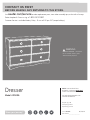
Dresser
Model 420456
NOTE: THIS INSTRUCTION
BOOKLET CONTAINS IMPORTANT
SAFETY INFORMATION.
PLEASE READ AND KEEP FOR
FUTURE REFERENCE.
English pg 1-18
Français pg 19-21
Español pg 22-24
Lot # 531427 07/18/19
Purchased: __________________
sauder.com
CONTACT US FIRST
BEFORE MAKING ANY RETURNS TO THE STORE.
Share your journey!
sauder.com
CONTACT US FIRST
BEFORE MAKING ANY RETURNS TO THE STORE.
Visit sauder.com/service to order replacement parts, view video assembly tips, or chat with a live rep.
Prefer the phone? Give us a ring at
1-800-523-3987.
Customer Service is available Monday-Friday - 9 a.m. to 5:30 p.m. EST (except holidays)
WARNING
CHOKING HAZARD - Small Parts
Not for children under 3 years.
Adult assembly required.

Part Identifi cation
Hardware Identifi cation
Assembly Steps
Français
Español
Safety
Warranty
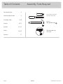
Hammer
Not actual size
No. 2 Phillips Screwdriver
Tip Shown Actual Size
Skip the power trip.
This time.
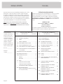
Table of Contents Assembly Tools Required
3
4
5-18
19-21
22-24
25-26
27
420456 www.sauder.com/servicePage 2

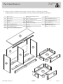
å While not all parts are labeled, some of the parts will have a label or an inked letter on the edge
to help distinguish similar parts from each other. Use this part identifi cation to help identify similar parts.
Part Identifi cation
Now you know
our ABCs.
A2 RIGHT END (1)
B2 LEFT END (1)
C2 UPRIGHT (1)
D TOP (1)
D36 RIGHT DRAWER SIDE (4)
D37 LEFT DRAWER SIDE (4)
D42 SMALL RIGHT DRAWER SIDE (2)
D43
SMALL LEFT DRAWER SIDE (2)
- 1 with label
D165 SMALL DRAWER BACK (2)
D167 DRAWER BACK (4)
D974 DRAWER BOTTOM (6)
E BACK (1)
F BRACE (4)
G2 BASE (1)
H LARGE DRAWER FRONT (4)
I SMALL DRAWER FRONT (2)
J TOP MOLDING (1)
M67
DRAWER BRACE (6)
(Hidden part using recycled
material. Color may vary.)
420456www.sauder.com/service
Page 3
A2
B2
C2
D
E
F
G2
H
I
J
F
F
F
D974
D974
D42
D43
D165
D36
D37
D167
M67
M67

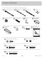
Hardware Identifi cation
å Screws are shown actual size. You may receive extra hardware with your unit.
420456 www.sauder.com/servicePage 4
SMALL DRAWER
FRONT BRACKET - 2
7G
DRAWER FRONT
BRACKET - 4
9G
35AA
UNIVERSAL CABINET RAIL - 12
35AC
DRAWER RIGHT - 6
35AD
DRAWER LEFT - 6
BLACK 1-1/8" PAN HEAD SCREW - 6
9S
METAL
BRACKET - 7
4G
BLACK 9/16" LARGE HEAD SCREW - 34
1S
SILVER 1-1/8" FLAT HEAD SCREW - 4
10S
3S
GOLD 5/16" FLAT HEAD SCREW - 48
TACK GLIDE - 6
13E
NAIL - 45
1N
HIDDEN CAM - 20
1F
CAM DOWEL - 20
2F
KNOB - 6
91K
30S
BLACK 1-9/16" FLAT HEAD SCREW - 30
FURNITURE TIPPING
RESTRAINT KIT - 1
97

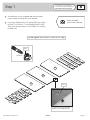
Step 1
Look for this icon. It means a
video assembly tip is available at
www.sauder.com/service/tips
å
Assemble your unit on a carpeted fl oor or on the empty
carton to avoid scratching your unit or the fl oor.
å
Push twenty HIDDEN CAMS (1F) into the ENDS (A2 and B2),
UPRIGHT (C2), BRACES (F), and DRAWER BRACES (M67).
Then, insert the metal end of a CAM DOWEL (2F) into each
HIDDEN CAM.
420456www.sauder.com/service
Page 5
(20 used)
Arrow
1F
2F
Do not tighten the HIDDEN CAMS in this step.
Insert the metal end of the CAM
DOWEL into the HIDDEN CAM.
Arrow
A2
B2
C2
F
F
F
F
M67
M67
M67
M67
M67
M67
Some assembly
(and snacks) required.

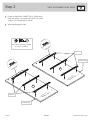
Step 2
420456 www.sauder.com/servicePage 6
å
Fasten six UNIVERSAL CABINET RAILS* (35AA) to the
ENDS (A2 and B2). Use twelve GOLD 5/16" FLAT HEAD
SCREWS (3S) through holes #1 and #3.
å
*patent pending glide system
GOLD 5/16" FLAT HEAD SCREW
(12 used for the RAILS)
3S
3
2
1
1
2
3
VIEW THE DRAWER GLIDE VIDEO
1
2
3
1
2
3
3
2
1
3
2
1
A2
B2
Surface with
HIDDEN CAMS
Surface with
HIDDEN CAMS
Finished edge
Finished edge
Glide end
Glide end

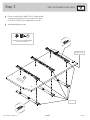
Step 3
420456www.sauder.com/service
Page 7
å
Fasten six UNIVERSAL CABINET RAILS* (35AA) to both
surfaces of the UPRIGHT (C2). Use twelve GOLD 5/16"
FLAT HEAD SCREWS (3S) through holes #1 and #3.
å
*patent pending glide system
GOLD 5/16" FLAT HEAD SCREW
(12 used for the RAILS)
3S
1
2
3
VIEW THE DRAWER GLIDE VIDEO
Finished edge
Surface with
HIDDEN CAMS
C2
1
2
3
1
2
3
1
2
3
1
2
1
2
Glide end

å
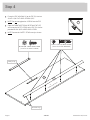
Fasten the TOP MOLDING (J) to the TOP (D). Use four
SILVER 1-1/8" FLAT HEAD SCREWS (10S).
å
NOTE: Do not overtighten the SCREWS into the TOP.
å
Open the FURNITURE TIPPING RESTRAINT KIT (97)
and fasten the SAFETY STRAP to the TOP (D). Use the
provided BLACK 9/16" LARGE HEAD SCREW.
å
NOTE: Position the SAFETY STRAP exactly as shown.
Step 4
420456 www.sauder.com/servicePage 8
D
J
Rounded edge
SILVER 1-1/8" FLAT HEAD SCREW
(4 used for the TOP MOLDING)
10S
Surface with holes
BLACK 9/16" LARGE HEAD SCREW
(1 used for the SAFETY STRAP)
Safety strap
97

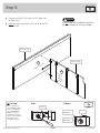
å
Fasten the UPRIGHT (C2) to the TOP (D). Tighten two
HIDDEN CAMS.
å
NOTE: Be sure to move the SAFETY STRAP on the TOP
o to one side.
Step 5
420456www.sauder.com/service
Page 9
Start Tighten
Arrow
Minimum
190 degrees
Caution
Risk of damage or
injury. HIDDEN CAMS
must be completely
tightened. HIDDEN
CAMS that are not
completely tightened
may loosen, and parts
may separate. To
completely tighten:
Arrow
Maximum
210 degrees
Do not stand the unit upright without the
BACK fastened. The unit may collapse.
Caution
D
Surface with holes
C2
Finished edge
Rounded edge
Surface
with
HIDDEN
CAMS

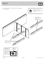
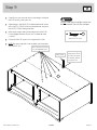
å
Fasten the BRACES (F) to the UPRIGHT (C2). Tighten four
HIDDEN CAMS.
Step 6
420456 www.sauder.com/servicePage 10
Arrow
Minimum
190 degrees
Maximum
210 degrees
C2
F
Surface with HIDDEN CAMS
These holes
must be here.
Don't worry. It isn't
Rome. This can be built
in a day.
F
Surface with HIDDEN CAMS
F
Surface with HIDDEN CAMS
F
Surface with HIDDEN CAMS
These holes
must be here.

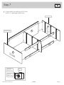
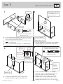
å
Fasten the ENDS (A2 and B2) to the TOP (D) and
BRACES (F). Tighten eight HIDDEN CAMS.
Step 7
420456www.sauder.com/service
Page 11
Arrow
Minimum
190 degrees
Maximum
210 degrees
F
F
F
F
D
A2
B2
Surface
with
HIDDEN
CAMS
Surface without
HIDDEN CAMS
Finished edge
Finished edge

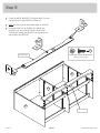
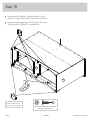
Step 8
420456 www.sauder.com/servicePage 12
å
Fasten fi ve METAL BRACKETS (4G) to the BASE (G2). Use
fi ve BLACK 9/16" LARGE HEAD SCREWS (1S).
å
NOTE: Be sure to use the exact holes shown in the BASE.
å
Fasten the BASE (G2) to the ENDS (A2 and B2) and
UPRIGHT (C2). Use fi ve BLACK 9/16" LARGE HEAD
SCREWS (1S) through the BRACKETS on the BASE and
into the ENDS and UPRIGHT.
BLACK 9/16" LARGE HEAD SCREW
(10 used in this step)
1S
A2
B2
C2
G2
G2
4G
4G
4G
Curved edge
Curved edge

Step 9
420456www.sauder.com/service
Page 13
å
Carefully turn your unit over onto its front edges. Unfold the
BACK (E) and lay it over your unit.
å
A perforation in the BACK (E) has been provided for access
to the SAFETY STRAP. Punch out the perforation and push
the SAFETY STRAP through the hole.
å
Make equal margins along all four edges of the BACK (E).
Push on opposite corners of your unit if needed to make
it "square".
å
Fasten the BACK (E) to your unit using the NAILS (1N).
å
NOTE: Be sure to tap NAILS into the holes that line up over
the UPRIGHT (C2).
Do not stand the unit upright without the
BACK fastened. The unit may collapse.
Caution
NAIL
(45 used in this step)
1N
E
These holes must line up
over the UPRIGHT (C2).
Before fastening the
BACK, punch out the
perforation and push
the SAFETY STRAP
through the hole.
Safety strap

å
Fasten two METAL BRACKETS (4G) to the BRACES (F) and
BASE (G2). Use four BLACK 9/16" LARGE HEAD SCREWS (1S).
å
Using your hammer, gently tap six TACK GLIDES (13E) into the
ENDS (A2 and B2), UPRIGHT (C2), and BASE (G2).
Step 10
420456 www.sauder.com/servicePage 14
BLACK 9/16" LARGE HEAD SCREW
(4 used for the BRACKETS)
1S
4G
G2
F
F
13E
B2
A2
C2
13E
These two TACK GLIDES
should be fl ush with the
front surface of the BASE.

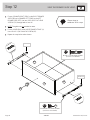
Step 11
420456www.sauder.com/service
Page 15
VIEW THE T-SLOT BOX VIDEO
1
3
2
4
å
Pull the DRAWER FRONT BRACKETS (9G) apart and slide them
into the grooves in the DRAWER SIDES (D36 and D37). You may
need to gently tap them in with a hammer.
å
NOTE: The DRAWER FRONT BRACKETS are marked "RH" and
"LH" for easy identifi cation.
å
Fasten the LARGE DRAWER FRONT (H) to the DRAWER FRONT
BRACKETS (9G). Use four BLACK 9/16" LARGE HEAD SCREWS (1S).
å
Slide the DRAWER BOTTOM (D974) into the grooves
in the DRAWER SIDES (D36 and D37) and LARGE
DRAWER FRONT (H).
å
Fasten the DRAWER BRACE (M67) to the LARGE
DRAWER FRONT (H). Tighten one HIDDEN CAM.
å
Fasten the DRAWER BACK (D167) to the DRAWER
SIDES (D36 and D37) and DRAWER BRACE (M67). Use
fi ve BLACK 1-9/16" FLAT HEAD SCREWS (30S).
å
Repeat this step for the other drawers. Use the SMALL
DRAWER FRONT (I), SMALL DRAWER SIDES (D42
and D43), SMALL DRAWER BACK (D165), and SMALL
DRAWER FRONT BRACKETS (7G) for the small drawers.
BLACK 9/16" LARGE HEAD SCREW
(20 used in this step)
1S
D36
D974
D167
D37
H
H
Be sure the DRAWER
BOTTOM inserts into the
DRAWER FRONT groove.
Be sure the
DRAWER
BOTTOM
inserts into
the DRAWER
BACK groove.
With the palm of your hand,
tap the DRAWER BOTTOM
down into the groove.
30S
Start each screw a few turns before
completely tightening any of them.
BLACK 1-9/16" FLAT HEAD SCREW
(30 used in this step)
M67
Arrow
Maximum
210 degrees
Minimum
190 degrees
Groove
D36
D37
H
D36
D37
M67
9G
Unfi nished surface
Push down
Surface with
HIDDEN CAM
Hidden part using
recycled material.
Color may vary.

Step 12
420456 www.sauder.com/servicePage 16
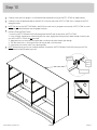
å
Fasten a DRAWER RIGHT (35AC) to the RIGHT DRAWER
SIDE (D36) and a DRAWER LEFT (35AD) to the LEFT
DRAWER SIDE (D37). Use four GOLD 5/16" FLAT HEAD
SCREWS (3S) through holes #1 and #2.
å
NOTE: The glides are not intended to rotate.
å
Fasten a KNOB (91K) to the LARGE DRAWER FRONT (H).
Use a BLACK 1-1/8" PAN HEAD SCREW (9S).
å
Repeat this step for the other drawers.
1
2
1
2
VIEW THE DRAWER GLIDE VIDEO
Almost time to
celebrate! With a nap.
9S
BLACK 1-1/8" PAN HEAD SCREW
(6 used for the KNOBS)
GOLD 5/16" FLAT HEAD SCREW
(24 used for the SLIDES)
3S
H
D36
D37
91K
Glide end
Glide end

Step 13
420456www.sauder.com/service
Page 17
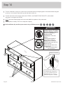
å
Carefully stand your unit upright in its fi nal location. We recommend using the SAFETY STRAP for added stability.
å
Carefully cut out the perforated hole in the BACK (E). Insert the end of the SAFETY STRAP that is fastened to the TOP
through this hole.
å
NOTE: Do not turn the SAFETY DRYWALL ANCHOR into a wall stud. If you prefer to fasten the SAFETY STRAP to a wall
stud, go to your local hardware store for proper hardware.
å
INSTALLATION INSTRUCTIONS:
1. Insert the SAFETY DRYWALL ANCHOR through the WASHER and the end of the SAFETY STRAP.
2. Using a Phillips screwdriver or a hand drill, press the screw slightly onto the drywall just below the top surface of your
unit so the SAFETY STRAP will not be visible.
3. Apply pressure; turn the screw until a pilot hole is made and the nylon sheath slips through.
4. Turn the screw until it is fl ush against the wall and you feel a fi rm resistance.
5. Continue to turn until the screw starts spinning freely.
å
NOTE: Before moving your unit to a di erent location, unscrew the SAFETY DRYWALL ANCHOR from your wall. The
nylon sheath will remain behind your wall.
E
Safety
drywall
anchor
Safety strap
Washer
97

WA
R
N
I
N
G
AV
E
RT
IS
S
E
M
E
N
T
ADV
E
RT
E
N
C
IA
oc
cur
from
furn
iture tip-
over.
T
o help
preve
nt tip-
o
ve
r:
• Ins
tall tip-
over restraint provided.
• Place heaviest item
s in
the l
o
wer
drawers.
•
D
o
n
o
t
s
e
t
T
V
’
s
o
r
o
th
e
r
h
e
a
v
y
o
b
je
c
t
s
o
n
t
o
p
o
f
th
is
p
r
o
d
u
c
t
, u
n
l
e
s
s
t
h
e
p
r
o
d
u
c
t i
s
dra
wers, d
oors
, or shelves.
• Ne
ve
r o
pen
m
ore tha
n o
ne dra
wer at
a time.
Use of tip-over restrain
ts m
ay only
reduce, but not elim
inat
e, the risk of
tip-over.
This is a pe
rm
an
en
t la
bel. Do
not rem
o
ve!
écrasem
ent peuvent su
rvenir si le
m
obilier
bascul
e
. Pou
r p
ré
venir le ba
scule
m
ent :
• Installer le d
ispositif anti-ba
sculem
ent fourni.
• Placer les
a
rticles
plus
lourds dans les
tiroirs
infé
rieur
s
.
• Ne pa
s m
ettre
d
e téléviseur ou
d
’autre objets
lourds sur le
des
sus de ce meub
l
e,
sauf si le
• Ne ja
m
ais ouvrir plus
d’un tiroir à la fois.
L’utilisation
de dispos
itifs anti-basc
ulem
ent
pe
ut réduire le ris
qu
e de b
asculem
e
nt
,
m
ais
pas
l
’élim
ine
r.
C
ette é
tiquette
es
t pe
rm
anen
t
e
. N
e pas
l’enlever!
pueden
o
currir
por el volc
ar de lo
s m
ueble
s
.
Para ayudar a prevenir q
ue se vo
lqué:
• Instala
r la co
nt
ención b
rindada
p
ara evitar
que se vo
lqu
é.
• Co
lo
que los a
r
t
ículos m
ás pesa
dos
en los
cajo
nes inferiore
s.
•
No co
lo
que telev
isores u otro
s o
bjetos
pesa
do
s en
la pa
rte sup
erior d
e es
te pro
duct
o,
diseñ
ado
para
a
com
od
arlo
s.
• Nun
ca p
erm
ita que los niño
s s
e suban o
se
• N
unca
abra m
ás
de u
n cajón a la v
ez.
E
l uso de la conten
ció
n pue
de solam
en
te
Esta es
una
etiqueta perm
an
ent
e. ¡N
o remove
r!
Step 14
420456 www.sauder.com/servicePage 18
å
To insert the drawers into your unit, tip the front of the drawers down and drop the glides on the drawers behind the glides
on the unit. Lift the front of the drawers up and slide them into the unit.
å
To make adjustments to the drawers, loosen the SCREWS in the DRAWER FRONT BRACKETS, make needed
adjustments, and tighten the SCREWS.
å
NOTE: Please read the back pages of the instruction booklet for important safety information.
å
This completes assembly. Clean with a damp cloth. Wipe dry.
20 lbs.
20 lbs.
I
I
H
H
H
25 lbs. each
H
50 lbs.
WARNING
Children have died from
furniture tipover. To reduce
the risk of furniture tipover:
• ALWAYS install tipover
restraint provided.
• NEVER put a TV on this
product.
• NEVER allow children to
stand, climb, or hang on
drawers, doors, or shelves.
• NEVER open more than one
drawer at a time.
• Place heaviest items in the
lowest drawers.
This is a permanent label.
Do not remove!
1/19 526119
And to celebrate, why not share your success story at Walmart.com or
To adjust the DRAWER FRONT using
the DRAWER FRONT BRACKETS,
loosen these SCREWS, adjust the
DRAWER FRONT up or down as
needed, then tighten the SCREWS.
Drawer Side
Drawer Front
Drawer front bracket

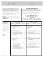
LISTE DE PIÈCES
REFERENCE DESCRIPTION QUANTITÉ
LISTE DE PIÈCES
REFERENCE DESCRIPTION QUANTITÉ
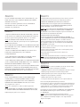
NOUS SOMMES LA POUR VOUS AIDER!
Nous faisons de notre mieux pour nous assurer que votre meuble
arrive dans d’excellentes conditions. Nos représentants du service
Clientèle sont aimables et prêts à vous aider au cas où une pièce
aurait été endommagée ou manquerait (ou si vous aviez besoin
d’aide pour l’assemblage). NE RAMENEZ PAS LE MEUBLE AU
MAGASIN. Au Canada, composez ce numéro d’appel gratuit:
1-800-523-3987
Du lundi au vendredi, de 9 heures du matin à
5:30 heures du soir (horaire Côte Est)
(sauf jours fériés)
Si une pièce a besoin d’être remplacée, la pièce de remplacement
sera envoyée dans les 48 heures. (Sauf week-ends et jours fériés)
Utilisez les instructions d’assemblage en français avec les
schémas étape par étape du manuel d’instruction en anglais.
Chaque étape en français correspond à la même étape
en anglais. La pièce devant être attachée à l’élément est
représentée en gris sur les schémas de chaque étape pour plus
de précision. Comparer la “Liste de pièces” ci-dessous avec
la “PART IDENTIFICATION” du manuel en anglais pour vous
familiariser avec les pièces avant l’assemblage.
REMARQUE : CE MANUEL D’INSTRUCTIONS CONTIENT
D’IMPORTANTES INFORMATIONS RELATIVES À LA SÉCURITÉ.
À LIRE ET CONSERVER POUR TOUTE RÉFÉRENCE FUTURE.
Noter la date d’achat
de cet élément et
conserver le livret pour
future référence. Pour
contacter Sauder en
ce qui concerne cet
élément, faire référence
au numéro de lot et
numéro de modèle en
appelant notre numéro
sans frais.
Lot nº : ____________
Date de
l'achet : ____________
35AA
GLISSIÈRE D'ÉLÉMENT UNIVERSELLE...12
35AC
TIROIR DROIT ................................................................6
35AD
TIROIR GAUCHE ..........................................................6
13E PATIN .....................................................................................6
1F EXCENTRIQUE ESCAMOTABLE .................20
2F CHEVILLE D'EXCENTRIQUE ..........................20
4G CONSOLE EN MÉTAL .............................................7
7G CONSOLE DE DEVANT DE PETIT TIROIR .........2
9G CONSOLE DE DEVANT DE TIROIR ..............4
91K BOUTON ............................................................................6
1N CLOU ................................................................................45
97 KIT DE RETENUE ANTI-BASCULEMENT
POUR MOBILIER...........................................................1
1S VIS TÊTE LARGE 14 mm NOIRE ................. 34
3S VIS TÊTE PLATE 8 mm DORÉE ..................48
9S VIS TÊTE GOUTTE DE
SUIF 28 mm NOIRE ..................................................6
10S VIS TÊTE PLATE 28 mm ARGENTÉE .........4
30S VIS TÊTE PLATE 40 mm NOIRE ................30
A2 EXTRÉMITÉ DROITE ..................................................1
B2 EXTRÉMITÉ GAUCHE ...............................................1
C2 MONTANT..........................................................................1
D DESSUS ...............................................................................1
D36 CÔTÉ DROIT DE TIROIR .......................................4
D37 CÔTÉ GAUCHE DE TIROIR .................................4
D42 CÔTÉ DROIT DE PETIT TIROIR .......................2
D43 CÔTÉ GAUCHE DE PETIT TIROIR.................2
1 avec étiquette
D165 ARRIÈRE DE PETIT TIROIR ..................................2
D167 ARRIÈRE DE TIROIR ..................................................4
D974 FOND DE TIROIR .........................................................6
E ARRIÈRE ..............................................................................1
F ENTRETOISE...................................................................4
G2 BASE ......................................................................................1
H DEVANT DE GRAND TIROIR ..............................4
I DEVANT DE PETIT TIROIR ..................................2
J MOULURE DE DESSUS ..........................................1
M67 ENTRETOISE DE TIROIR
(Pièce cachée utilisant des matériaux
recyclés. La couleur peut varier.) ......................6
CommodeModèle 420456
420456www.sauder.com/service
Page 19

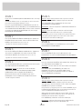
ÉTAPE 8
Fixer cinq CONSOLES EN MÉTAL (4G) au BASE (G2). Utiliser cinq
VIS TÊTE LARGE 14 mm NOIRES (1S).
REMARQUE : S’assurer d’utiliser les trous exacts illustrés dans la BASE.
Fixer la BASE (G2) aux EXTRÉMITÉS (A2 et B2) et au
MONTANT (C2). Utiliser cinq VIS TÊTE LARGE 14 mm
NOIRES (1S) à travers les CONSOLES situées sur la BASE, et
dans les EXTRÉMITÉS et MONTANT.
ÉTAPE 7
Fixer les EXTRÉMITÉS (A2 et B2) au DESSUS (D) et aux
ENTRETOISES (F). Serrer huit EXCENTRIQUES ESCAMOTABLES.
ÉTAPE 6
Fixer les ENTRETOISES (F) au MONTANT (C2). Serrer quatre
EXCENTRIQUES ESCAMOTABLES.
ÉTAPE 5
Attention: Ne pas relever l'élément dans sa position verticale
avant d'avoir fi xé l’ARRIÈRE. L'élément risque de s'e ondrer.
Fixer le MONTANT (C2) sur le DESSUS (D). Serrer deux
EXCENTRIQUES ESCAMOTABLES.
REMARQUE : S'assurer de déplacer la SANGLE DE SÉCURITÉ du
DESSUS sur un côté.
Attention: Risque des dégâts ou blessures. Les Excentriques
Escamotables doivent être serrés à bloc. Les Excentriques
Escamotables que ne sont pas serrées à bloc peuvent desserrer
et les pièces peuvent séparer. Pour serrer à bloc, faire tourner
l'excentrique escamotable de 210 degrés.
ÉTAPE 4
Fixer la MOULURE DE DESSUS (J) au DESSUS (D). Utiliser quatre
VIS TÊTE PLATE 28 mm ARGENTÉES (10S).
REMARQUE : Ne pas trop serrer les VIS dans le DESSUS.
Ouvrir le KIT DE RETENUE ANTI-BASCULEMENT POUR
MOBILIER (97) et fi xer la SANGLE DE SÉCURITÉ au
DESSUS (D). Utiliser la VIS TÊTE LARGE 14 mm fourni.
REMARQUE : Placer la SANGLE DE SÉCURITÉ exactement
comme l'indique le schéma.
ÉTAPE 3
Fixer six GLISSIÈRES D'ÉLÉMENT UNIVERSELLES * (35AA) aux
deux surfaces du MONTANT (C2). Utiliser douze VIS TÊTE
PLATE 8 mm DORÉES (3S) à travers les trous nº 1 et nº 3.
*système de coulisse en instance de brevet
ÉTAPE 2
Fixer six GLISSIÈRES D'ÉLÉMENT UNIVERSELLES* (35AA) aux
EXTRÉMITÉS (A2 et B2). Utiliser douze VIS TÊTE PLATE 8 mm
DORÉES (3S) à travers les trous nº 1 et nº 3.
*système de coulisse en instance de brevet
ÉTAPE 1
Ne pas serrer les EXCENTRIQUES ESCAMOTABLES dans cette étape.
Assembler l'élément sur un sol à moquette ou sur le carton vide
pour éviter d'endommager l'élément ou le sol.
Enfoncer vingt EXCENTRIQUES ESCAMOTABLES (1F) dans les
EXTRÉMITÉS (A2 et B2), le MONTANT (C2), les ENTRETOISES (F)
et les ENTRETOISES DE TIROIR (M67). Ensuite, insérer l'extrémité
en métal de la CHEVILLE D'EXCENTRIQUE (2F) dans chaque
EXCENTRIQUE ESCAMOTABLE.
420456 www.sauder.com/servicePage 20
ÉTAPE 9
Attention: Ne pas relever l'élément dans sa position verticale
avant d'avoir fi xé l’ARRIÈRE. L'élément risque de s'e ondrer.
Avec précaution, retourner l'élément sur ses chants avant. Déplier
l'ARRIÈRE (E) et le placer sur l'élément.
Une perforation ont été prévue pour accès à travers l’ARRIÈRE (F) pour
la SANGLE DE SÉCURITÉ. Découper soigneusement la perforation et
enfoncer la SANGLE DE SÉCURITÉ à travers le trou.
Veiller à avoir des marges égales le long des quatre chants de
l'ARRIÈRE (E). Si besoin est, enfoncer sur les coins opposés de
l'élément pour s'assurer d'être « d'équerre ».
Fixer l'ARRIÈRE (E) à l'élément à l'aide des CLOUS (1N).
REMARQUE : S'assurer de bien enfoncer les CLOUS dans les
trous qui sont alignés au-dessus le MONTANT (C2).
La page est en cours de chargement...
La page est en cours de chargement...
La page est en cours de chargement...
La page est en cours de chargement...
La page est en cours de chargement...
La page est en cours de chargement...
La page est en cours de chargement...
La page est en cours de chargement...
-
 1
1
-
 2
2
-
 3
3
-
 4
4
-
 5
5
-
 6
6
-
 7
7
-
 8
8
-
 9
9
-
 10
10
-
 11
11
-
 12
12
-
 13
13
-
 14
14
-
 15
15
-
 16
16
-
 17
17
-
 18
18
-
 19
19
-
 20
20
-
 21
21
-
 22
22
-
 23
23
-
 24
24
-
 25
25
-
 26
26
-
 27
27
-
 28
28


dans d''autres langues
- English: Sauder 420456 Operating instructions
- español: Sauder 420456 Instrucciones de operación
Documents connexes
-
Sauder 416407 Mode d'emploi
-
-
-
-
-
-
-
-
-
