La page est en cours de chargement...

1
Wood Assembly
2
Divider
3
Holder Assembly
4
TRI-Slide Assembly
5
Adjustable Mounting Bracket (AMB Brackets)
6
Carriage Bolt
7
Flat Washer
8
Lock Nut
9
T-Nut
10
T-Nut Bolt
11
#8 x 3/4 Pan Head Sheet Metal Screws
12
#6 x 1/2 Flat Head Sheet Metal Screws
13
Adjustable Rub Bushing
14 Adjustable Rub Bushing Installation Kit
with Instruction Sheet (I-ARBKIT-0312)
15
447 Series Instruction Sheet
MATERIALS
2
4
5
9 10
6 7 8
3
1
12
11
13
1
Wood Assembly
2
Divider
3
Holder Assembly
4
TRI-Slide Assembly
5
Adjustable Mounting Bracket (AMB Brackets)
6
Carriage Bolt
7
Flat Washer
8
Lock Nut
9
T-Nut
10
T-Nut Bolt
11
#8 x 3/4 Pan Head Sheet Metal Screws
12
#6 x 1/2 Flat Head Sheet Metal Screws
13
Adjustable Rub Bushing
14 Adjustable Rub Bushing Installation Kit
with Instruction Sheet (I-ARBKIT-0312)
15
447 Series Instruction Sheet (I-447-TRI-0815)
MATERIALS
I-447-1115-TRI
2
4
5
9 10
6 7 8
3
1
12
11
13
1Wood Assembly
2 Divider
3Holder Assembly
4TRI-Slide Assembly
5Adjustable Mounting Bracket (AMB Brackets)
6Carriage Bolt
7Flat Washer
8Lock Nut
9T-Nut
10T-Nut Bolt
11#8 x 3/4 Pan Head Sheet Metal Screws
12#6 x 1/2 Flat Head Sheet Metal Screws
13Adjustable Rub Bushing
14Adjustable Rub Bushing Installation Kit
with Instruction Sheet (I-ARBKIT-0312)
15447 Series Instruction Sheet (I-447-TRI-0815)
INSTALLATION INSTRUCTIONS: 447 SERIES TRAY / WRAP ORGANIZERS
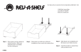
STEP 1
See FIGURE 2
Center cabinet slide assembly on
cabinet oor 7/8” from front outside
edge of cabinet.
NOTE
If installing into a cabinet with an
inset door, move the slide assembly
back additionally the thickness of the
door.
STEP 2 STEP 3
See FIGURE 1
Disengage cabinet slide assembly
from unit by pressing release levers
on the two vertical slides and
pulling unit away from cabinet slide
assembly.
See FIGURE 3
Mount cabinet slide assembly to
cabinet oor with provided screws.
FIGURE 3
FIGURE 2
FIGURE 1
MATERIALS
INSTALLATION
INSTRUCTIONS
447 SERIES TRAY / WRAP ORGANIZERS
12400 Earl Jones Way, Louisville, KY 40299
(800) 626-1126 | www.rev-a-shelf.com
ESTIMATED ASSEMBLY
TIME:
20 MIN
CARE AND MAINTENANCE:
TO CLEAN, WIPE WITH A
DAMP CLOTH
PART # I-447-TRI-0815
TOOLS REQUIRED:
3
32
#2
#2
3
8
2
4
5
910
678
3
1
12
11
13
1Wood Assembly
2 Divider
3Holder Assembly
4TRI-Slide Assembly
5Adjustable Mounting Bracket (AMB Brackets)
6Carriage Bolt
7Flat Washer
8Lock Nut
9T-Nut
10T-Nut Bolt
11#8 x 3/4 Pan Head Sheet Metal Screws
12#6 x 1/2 Flat Head Sheet Metal Screws
13Adjustable Rub Bushing
14Adjustable Rub Bushing Installation Kit
with Instruction Sheet (I-ARBKIT-0312)
15447 Series Instruction Sheet (I-447-TRI-0815)
INSTALLATION INSTRUCTIONS: 447 SERIES TRAY / WRAP ORGANIZERS
STEP 1
See FIGURE 2
Center cabinet slide assembly on
cabinet oor 7/8” from front outside
edge of cabinet.
NOTE
If installing into a cabinet with an
inset door, move the slide assembly
back additionally the thickness of the
door.
STEP 2 STEP 3
See FIGURE 1
Disengage cabinet slide assembly
from unit by pressing release levers
on the two vertical slides and
pulling unit away from cabinet slide
assembly.
See FIGURE 3
Mount cabinet slide assembly to
cabinet oor with provided screws.
FIGURE 3
FIGURE 2
FIGURE 1
MATERIALS
INSTALLATION
INSTRUCTIONS
447 SERIES TRAY / WRAP ORGANIZERS
12400 Earl Jones Way, Louisville, KY 40299
(800) 626-1126 | www.rev-a-shelf.com
ESTIMATED ASSEMBLY
TIME:
20 MIN
CARE AND MAINTENANCE:
TO CLEAN, WIPE WITH A
DAMP CLOTH
PART # I-447-TRI-0815
TOOLS REQUIRED:
3
32
#2
#2
3
8
2
4
5
910
678
3
1
12
11
13
15
Screws installed to the oor
14
15
Screws installed to the oor
14
15
14
12400 Earl Jones Way
Louisville, KY 40299
rev-a-shelf.com
Customer Service: 800-626-1126
447 SERIES TRAY / WRAP ORGANIZERS
TOOLS REQUIRED:
20 MIN
ESTIMATED ASSEMBLY TIME:
CARE AND MAINTENANCE:
Clean with a damp cloth and
wipe parts dry.
7
64
3
32
2
mm
#2
3
8
15
14
12400 Earl Jones Way
Louisville, KY 40299
rev-a-shelf.com
Customer Service: 800-626-1126
447 SERIES TRAY / WRAP ORGANIZERS
TOOLS REQUIRED:
20 MIN
ESTIMATED ASSEMBLY TIME:
CARE AND MAINTENANCE:
Clean with a damp cloth and
wipe parts dry.
7
64
3
32
2
mm
#2
3
8
I-447-1115-TRI

Customer Service: 800-626-1126 | rev-a-shelf.com
2
FIG. 1
Screws installed to the oor
Disengage cabinet slide
assembly from unit by
pressing release levers on the
two vertical slides and pulling
unit away from cabinet slide
assembly. (Fig 1)
STEP 1
STEP 2
Center cabinet slide assembly
on cabinet oor 7/8” from
front outside edge of cabinet.
(Fig 2)
Note
If installing into a cabinet with
an inset door, move the slide
assembly back additionally
the thickness of the door.
FIG. 2
STEP 3
Mount cabinet slide assembly
to cabinet oor with provided
screws. (Fig 3)
FIG. 3
7
64
3
32
2
mm
#2
#2

INSTALLATION INSTRUCTIONS: 447 SERIES TRAY / WRAP ORGANIZERS 3
Engage product slide
assembly to cabinet slide
assembly. (Fig 4)
NOTE
Before engaging the
product into the cabinet
slide assembly, be sure to
move the ball bearing tracks
found inside the cabinet slide
assembly to the front of the
slide assembly so they are
ush with the black mouth
piece caps.
STEP 4
FIG. 4
Attach door to unit. (Fig 5)
NOTE
Utilize the adjustable door
mounting brackets to ensure
mounting in thick portion of
cabinet door (front of product
should line up with front of
face frame). For ease of door
mounting, double sided tape
can be used, not included.
The AMB brackets will
allow for side to side door
adjustment but will not allow
for top to bottom door
adjustment.
STEP 5
=Thicker part of door
FIG. 5
7
64
3
32
2
mm
#2
3
8

Customer Service: 800-626-1126 | rev-a-shelf.com
4
Adjustment Screw
STEP 7
Tighten “Adjustment Screw”
(this will push mounting
bracket out) until cabinet
door is at desired position.
To add tilt to your door;
whether it be to the left,
right, top, or bottom, use the
adjustment screw. (Fig 6B)
FIG. 6B
Lock Nut/
T-Nut
FIG. 6A
To adjust your cabinet door
side to side use a 3/8-in
wrench, you will want to use
the “Lock Nut” adjustment,
refer to FIG 6A for the “Lock
Nut” location.
NOTE
All “Lock Nuts” must be
loose in order for the door
to move completely left or
right.
STEP 6
Door Adjustment Section
STEP 8
Tighten “T-Nut” to lock ller
against adjustment screws.
(Fig 6A)
NOTE
Refer to the “Adjustable
Rub Bushing Installation”
instructions, found in the
“Adjustable Rub Bushing
Kit” (refer to I-ARBKIT-0312),
included with this unit.
STEP 9
Rub Bushing Installation
Install the provided rub
bushings in line with the top
rails. (Fig 7)
NOTE
Wood frame will need to be
removed from the cabinet
once the appropriate rub
bushings have been selected
in order for the bushings to
be installed.
FIG. 7
3
8

5
1
Ensamble de madera / Assemblage en bois
2
División / Diviseur
3
Ensamble de soporte / Assemblage du support
4
Ensamble Tri-deslizantes / Assemblage de la Coulisse Triple
5
Soportes de Montaje Ajustable (Soportes AMB) / Support de Montage Réglable (Supports AMB)
6
Perno de coche / Boulon
7
Tuerca plana / Rondelle Plate
8
Tuerca de seguridad / Écrou de Blocage
9
Tuerca T / Écrou en T
10
Tuerca de cerrojo tipo T / Boulon de l’écrou en T
11
#8 x ¾ Tornillos de chapa metálica plana / Vis à tête ronde pour tôle #8 x 3/4
12
#6 x ½ Tornillos de chapa metálica de cabeza plana / Vis à tête plate pour tôle #6 x 1/2
13
Buje ajustable / Bague réglable
14 Equipo de instalación de buje ajustable con hoja de instrucciones (I-ARBKIT-0312)
Kit d’installation de la bague réglable avec instructions (I-ARBKIT-0312)
15
Hoja de instrucciones de las Series 15 447 / Instructions de la Série 447
MATERIALES / MATÉRIAUX
2
4
5
9 10
6 7 8
3
1
12
11
13
14
12400 Earl Jones Way
Louisville, KY 40299
rev-a-shelf.com
800-626-1126
SERIES DE BANDEJA 447/ORGANIZADORES PARA PLÁSTICOS
LA SÉRIE 447 D’ORGANISATEURS À PLATEAUX ET À PAPIER D’EMBALLAGE
20 MIN
7
64
3
32
2
mm
#2
3
8
INSTRUCCIONES DE INSTALACIÓN / LES INSTRUCTIONS D’INSTALLATION
Herramientas requeridas:
Outils Requis:
Tiempo estimado de ensamblado
Durée de l’installation:
Limpie con un paño húmedo y
seque las partes.
Nettoyer avec un chiffon humide et
essuyer pour sécher complètement.
Cuidado/ Entretien:
I-447-1115-TRI
1
Wood Assembly
2
Divider
3
Holder Assembly
4
TRI-Slide Assembly
5
Adjustable Mounting Bracket (AMB Brackets)
6
Carriage Bolt
7
Flat Washer
8
Lock Nut
9
T-Nut
10
T-Nut Bolt
11
#8 x 3/4 Pan Head Sheet Metal Screws
12
#6 x 1/2 Flat Head Sheet Metal Screws
13
Adjustable Rub Bushing
14 Adjustable Rub Bushing Installation Kit
with Instruction Sheet (I-ARBKIT-0312)
15
447 Series Instruction Sheet (I-447-TRI-0815)
MATERIALS
I-447-1115-TRI
2
4
5
9 10
6 7 8
3
1
12
11
13
1Wood Assembly
2 Divider
3Holder Assembly
4TRI-Slide Assembly
5Adjustable Mounting Bracket (AMB Brackets)
6Carriage Bolt
7Flat Washer
8Lock Nut
9T-Nut
10T-Nut Bolt
11#8 x 3/4 Pan Head Sheet Metal Screws
12#6 x 1/2 Flat Head Sheet Metal Screws
13Adjustable Rub Bushing
14Adjustable Rub Bushing Installation Kit
with Instruction Sheet (I-ARBKIT-0312)
15447 Series Instruction Sheet (I-447-TRI-0815)
INSTALLATION INSTRUCTIONS: 447 SERIES TRAY / WRAP ORGANIZERS
STEP 1
See FIGURE 2
Center cabinet slide assembly on
cabinet oor 7/8” from front outside
edge of cabinet.
NOTE
If installing into a cabinet with an
inset door, move the slide assembly
back additionally the thickness of the
door.
STEP 2 STEP 3
See FIGURE 1
Disengage cabinet slide assembly
from unit by pressing release levers
on the two vertical slides and
pulling unit away from cabinet slide
assembly.
See FIGURE 3
Mount cabinet slide assembly to
cabinet oor with provided screws.
FIGURE 3
FIGURE 2
FIGURE 1
MATERIALS
INSTALLATION
INSTRUCTIONS
447 SERIES TRAY / WRAP ORGANIZERS
12400 Earl Jones Way, Louisville, KY 40299
(800) 626-1126 | www.rev-a-shelf.com
ESTIMATED ASSEMBLY
TIME:
20 MIN
CARE AND MAINTENANCE:
TO CLEAN, WIPE WITH A
DAMP CLOTH
PART # I-447-TRI-0815
TOOLS REQUIRED:
3
32
#2
#2
3
8
2
4
5
910
678
3
1
12
11
13
15
Screws installed to the oor
14
15
Screws installed to the oor
14
15
14
12400 Earl Jones Way
Louisville, KY 40299
rev-a-shelf.com
Customer Service: 800-626-1126
447 SERIES TRAY / WRAP ORGANIZERS
TOOLS REQUIRED:
20 MIN
ESTIMATED ASSEMBLY TIME:
CARE AND MAINTENANCE:
Clean with a damp cloth and
wipe parts dry.
7
64
3
32
2
mm
#2
3
8
15

6
Suelte el ensamblado del gabinete de la unidad,
presionando la palanca de liberación en los dos
deslizantes verticales, jale la unidad fuera del
ensamble del deslizante del gabinete.
(Fig 1)
Désengagez l’assemblage de la coulisse de l’armoire
de l’unité en appuyant sur les leviers de dégagement
sur les deux coulisses verticales et en retirant l’unité
hors de l’assemblage de la coulisse de l’armoire.
(Fig 1)
1
2
Centre el deslizante del ensamble del gabinete
en el piso del gabinete de 7/8” de la parte de la
esquina frontal externa del gabinete. NOTA Si está
instalando dentro del gabinete con un inserto de
puerta, mueva el deslizante posterior ensamblado
adicionalmente al ancho de la puerta.
(Fig 2)
Centrez l’assemblage de la coulisse de l’armoire
sur le plancher à 2.22cm (7/8”) du bord extérieur
avant de l’armoire. REMARQUE Si l’installation se
fait dans une armoire avec une porte encastrée,
reculez l’assemblage de la coulisse encore en plus de
l’équivalent de l’épaisseur de la porte.
(Fig 2)
3
Monte el deslizante del gabinete al piso del
gabinete con los tornillos que se proveen.
(Fig 3)
Montez l’assemblage de la coulisse de l’armoire sur le
plancher de l’armoire avec les vis fournies.
(Fig 3)
800-626-1126 | rev-a-shelf.com
FIG. 1
FIG. 2
FIG. 3
7
64
3
32
2
mm
#2
#2

7
Enganche el deslizante del producto ensamblado
al deslizante del gabinete.
(Fig 4)
NOTA: Antes de enganchar el producto dentro del
deslizante del gabinete, asegúrese de mover al
frente los rieles de los baleros que se encuentran
dentro del ensamble de deslizante del gabinete
para que estén al ras con las cubiertas de boca
negra.
Engagez l’assemblage de la coulisse du produit dans
l’assemblage de la coulisse de l’armoire.
(Fig 4)
REMARQUE : Avant d’engager le produit dans
l’assemblage de la coulisse de l’armoire, assurez-
vous de déplacer les rails à roulement à billes, qui se
trouvent à l’intérieur de l’assemblage de la coulisse de
l’armoire, à l’avant de l’assemblage de la coulisse pour
qu’ils soient à ras des capuchons de l’embout noir.
4
5
Sujete la puerta a la unidad. (Fig 5)
NOTA Utilice los soportes de montaje ajustables
de la puerta para asegurar el montaje dentro de la
porción gruesa de la puerta del gabinete (el frente
del producto debe estar alineado con el frente
del marco). Para un montaje sencillo de la puerta,
puede utilizar cinta de doble lado, ésta no se
incluye. Los soportes AMB permitirán un ajuste de
la puerta de lado a lado pero no permitirá el ajuste
de la puerta de la parte superior a la parte inferior.
Fixez la porte à l’unité. (Fig 5)
REMARQUE : Utilisez les supports de montage pour
porte pour assurer le montage dans la partie épaisse
de la porte de l’armoire (l’avant du produit doit être
aligné avec l’avant du cadrage avant). Pour faciliter le
montage sur porte, du ruban double adhésion peut
être utilisé (non inclus). Les supports AMB permettront
un ajustement latéral de la porte, mais ne permettront
pas un ajustement de la porte de haut en bas.
FIG. 4
=Thicker part of door
FIG. 5
7
64
3
32
2
mm
#2
3
8

800-626-1126 | rev-a-shelf.com
8
Para ajustar el lado de la puerta de su gabinete, utilice una
llave de 3/8 pulgadas, usted querrá utilizar el ajuste de “Tuerca
de Seguridad”, reérase a la gura 6ª para la ubicación de la
“Tuerca de Seguridad”.
NOTA: Todas las “Tuercas de Seguridad”, deben estar sueltas a
n de que la puerta se mueva completamente a la izquierda o
a la derecha.
Pour un ajustement latéral de votre porte de l’armoire, utilisez une
clé 3/8-in, vous voudrez utiliser le réglage écrou de blocage (Lock
Nut), reportez-vous à L’ILLUSTRATION 6A pour l’emplacement de
l’écrou de blocage.
REMARQUE: Tous les écrous de blocage doivent être desserrés pour
que la porte puisse bouger complètement vers la gauche ou vers
la droite.
6
SECCIÓN DE AJUSTE DE LA PUERTA
SECTION SUR L’AJUSTEMENT DE LA PORTE
7
Apriete el “Tornillo de Ajuste” (esto empujará el soporte de
montaje hacia afuera) hasta que la puerta del gabinete está en
la posición deseada. Para añadir inclinación a su puerta, ya sea
para el lado izquierdo, derecho, lado superior o inferior, utilice
el tornillo de ajuste. (Fig 6B)
Serrez “la Vis de Réglage” (cela va pousser le support de montage
vers l’extérieur) jusqu’à ce que la porte de l’armoire soit à
l’emplacement désiré. Pour ajouter de l’inclinaison à votre porte,
que ce soit à gauche, à droite, en haut ou en bas, utilisez la vis de
réglage.
8
Apriete la Tuerca T para cerrar el relleno en contra de los tornillos
de ajuste.
NOTA Reérase a las Instrucciones de Instalación de los Bujes de
Fricción Ajustables que se encuentra en el Equipo de Bujes de
Fricción Ajustables (reérase a la hoja I-ARBKIT-0312), incluida en
esta unidad.(Fig 6A)
Serrez l’Écrou en T pour verrouiller le caisson de compensation
contre les vis de réglage
REMARQUE Reportez-vous aux instructions pour l’installation de la
bague réglable, qui se trouvent dans le “Kit de la Bague Réglable”
(voir I-ARBKIT-0312), fourni avec cette unité.
9
INSTALACIÓN DE BUJES DE FRICCIÓN
INSTALLATION DE LA BAGUE
Instale los bujes de fricción proveídos en línea con los rieles
superiores.(Fig 7)
NOTA El marco de madera necesita quitarse del gabinete una
vez que los bujes de fricción apropiados se hayan seleccionado
a n de que los bujes sean instalados.
Installez les bagues fournies en les alignant avec les rails du haut.
REMARQUE Le cadre en bois devra être sorti de l’armoire une fois
que les bagues appropriées ont été sélectionnées pour que les
bagues puissent être installées.
Adjustment Screw
FIG. 6B
Lock Nut/
T-Nut
FIG. 6A
FIG. 7
3
8
/