Panasonic SB-TP70 Manuel utilisateur
- Catégorie
- Subwoofers
- Taper
- Manuel utilisateur
Ce manuel convient également à

Operating Instructions
Model No. / Modèle
SB-TP70
RQT7694-Y
Speaker System
Il est recommandé de lire attentivement le présent manuel avant
d’utiliser l’appareil.
Conserver ce manuel.
Manuel d’utilisation
Enceintes acoustiques
PP
Contents
Supplied accessories . . . . . . . . . . . . . . . . . . . . . . . . . . . . . . . . . 2
IMPORTANT SAFETY INSTRUCTIONS . . . . . . . . . . . . . . . . . . . 4
Speaker setup . . . . . . . . . . . . . . . . . . . . . . . . . . . . . . . . . . . . . . . 5
Location . . . . . . . . . . . . . . . . . . . . . . . . . . . . . . . . . . . . . . . . . . . . 7
Connections . . . . . . . . . . . . . . . . . . . . . . . . . . . . . . . . . . . . . . . . 8
Subwoofer operation (SB-WA70) . . . . . . . . . . . . . . . . . . . . . . . . 9
Notes . . . . . . . . . . . . . . . . . . . . . . . . . . . . . . . . . . . . . . . . . . . . . 10
Maintenance . . . . . . . . . . . . . . . . . . . . . . . . . . . . . . . . . . . . . . . 10
Product service . . . . . . . . . . . . . . . . . . . . . . . . . . . . . . . . . . . . . .11
Specifications . . . . . . . . . . . . . . . . . . . . . . . . . . . . . . . . . . . . . . .11
Warranty (U.S.A.) . . . . . . . . . . . . . . . . . . . . . . . . . . . . . Back cover
Table des matières
Accessoires fournis . . . . . . . . . . . . . . . . . . . . . . . . . . . . . . . . . . 2
Précautions à prendre . . . . . . . . . . . . . . . . . . . . . . . . . . . . . . . . 4
Installation des enceintes . . . . . . . . . . . . . . . . . . . . . . . . . . . . . 5
Emplacement . . . . . . . . . . . . . . . . . . . . . . . . . . . . . . . . . . . . . . . . 7
Raccordements . . . . . . . . . . . . . . . . . . . . . . . . . . . . . . . . . . . . . . 8
Fonctionnement de l’enceinte d’extrêmes-graves (SB-WA70)
. . . 9
Remarques . . . . . . . . . . . . . . . . . . . . . . . . . . . . . . . . . . . . . . . . 10
Entretien . . . . . . . . . . . . . . . . . . . . . . . . . . . . . . . . . . . . . . . . . . 10
Service après-vente . . . . . . . . . . . . . . . . . . . . . . . . . . . . . . . . . . 11
Données techniques . . . . . . . . . . . . . . . . . . . . . . . . . . . . . . . . . . 11
Before connecting, operating or adjusting this product, please read
these instructions completely.
Please keep this manual for future reference.
User memo:
The model number and serial number of this product can be found
on either the back or the bottom of the unit.
Please note them in the space provided below and keep for future reference.
MODEL NUMBER SERIAL NUMBER
SB-FS70
SB-PC70
SB-WA70
Homologation:
Il est recommandé de noter, dans l’espace prévu ci-dessous, le numéro
de modèle et le numéro de série inscrits à l’arrière, ou sous le fond de
l’appareil, et de conserver ce manuel pour référence ultérieure.
NUMÉRO DE MODÈLE NUMÉRO DE SÉRIE
SB-FS70
SB-PC70
SB-WA70
DATE D’ACHAT
DÉTAILLANT
ADRESSE DU DÉTAILLANT
N
O
DE TÉLÉPHONE
DATE OF PURCHASE
DEALER NAME
DEALER ADDRESS
TELEPHONE NUMBER

RQT7694
2
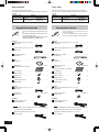
Accessoires fournis
Vérifier la présence et l’état des pièces et
accessoires suivants.
Lors de la commande de pièces de rechange,
utiliser les numéros indiqués entre parenthèses.
SB-FS70
Câbles de raccordement (long: 10 m) (32,8 pi) . . . . . . . . . . . 2
(REE1203C)
Câbles de raccordement (court: 4 m) (13,1 pi) . . . . . . . . . . . . 2
(REE1203A)
Stabilisateur assemblé . . . . . . . . . . . . . . . . . . . . . . . . . . . . . . 4
(RYQ0526-S)
Socle . . . . . . . . . . . . . . . . . . . . . . . . . . . . . . . . . . . . . . . . . . . . 4
(RYQ0521-S)
Pieds en caoutchouc . . . . . . . . . . . . . . . . . . . . . . . 1 feuille (24)
(RFA2645A)
(pièce de rechange - 6 par feuille)
Vis pour base . . . . . . . . . . . . . . . . . . . . . . . . . . . . . . . . . . . . . 8
(XTB4+30GFZ)
Collier en nylon . . . . . . . . . . . . . . . . . . . . . . . . . . . . . . . . . . . . 4
(RMR1503-W)
Vis pour collier en nylon . . . . . . . . . . . . . . . . . . . . . . . . . . . . . 4
(XTB3+8JFN)
SB-PC70
Câbles de raccordement (court: 4 m) (13,1 pi) . . . . . . . . . . . . 1
(REE1203A)
Pieds pour enceintes . . . . . . . . . . . . . . . . . . . . . . . . 1 feuille (4)
(RFA0631A-K)
SB-WA70
Cordon d’alimentation c.a. . . . . . . . . . . . . . . . . . . . . . . . . . . . 1
(K2CB2CB00006)
Nota
Le cordon d’alimentation fourni est pour utilisation exclusive avec
cet appareil. Ne pas I’utiliser avec un autre appareil.
Câble de raccordement monaural (5 m) (16,4 pi) . . . . . . . . . . 1
(RJL1P015B50)
Supplied accessories
Please check and identify the supplied accesso-
ries.
Use numbers indicated in parentheses when ask-
ing for replacement parts.
In U.S.A. to order accessories, refer to “Ac-
cessory Purchases” on back cover.
SB-FS70
Speaker cables (long: 10 m) (32.8 ft) . . . . . . . . . . . . . . . . . . . 2
(REE1203C)
Speaker cables (short: 4 m) (13.1 ft) . . . . . . . . . . . . . . . . . . . 2
(REE1203A)
Assembled stabilizer . . . . . . . . . . . . . . . . . . . . . . . . . . . . . . . . 4
(RYQ0526-S)
Base . . . . . . . . . . . . . . . . . . . . . . . . . . . . . . . . . . . . . . . . . . . . 4
(RYQ0521-S)
Rubber pads . . . . . . . . . . . . . . . . . . . . . . . . . . 1 sheet (24 feet)
(RFA2645A) (6 feet per sheet)
Screw for base . . . . . . . . . . . . . . . . . . . . . . . . . . . . . . . . . . . . 8
(XTB4+30GFZ)
Nylon clamp . . . . . . . . . . . . . . . . . . . . . . . . . . . . . . . . . . . . . . 4
(RMR1503-W)
Screw for nylon clamp . . . . . . . . . . . . . . . . . . . . . . . . . . . . . . 4
(XTB3+8JFN)
SB-PC70
Speaker cables (short: 4 m) (13.1 ft) . . . . . . . . . . . . . . . . . . . 1
(REE1203A)
Speaker feet . . . . . . . . . . . . . . . . . . . . . . . . . . . 1 sheet (4 feet)
(RFA0631A-K)
SB-WA70
AC power supply cord . . . . . . . . . . . . . . . . . . . . . . . . . . . . . . 1
(K2CB2CB00006)
Note
The included AC power supply cord is for use with this unit only.
Do not use it with other equipment.
Monaural connection cable (5 m) (16.4 ft) . . . . . . . . . . . . . . . 1
(RJL1P015B50)
Dear customer
Thank you for purchasing this product.
For optimum performance and safety, please read these instructions
carefully.
Cher client
Nous vous remercions d’avoir arrêté votre choix sur cet appareil.
Pour en tirer un rendement optimal, lire attentivement le présent
manuel.
Speaker system Speaker
SB-FS70 Front, Surround SB-FS70 X 4
SB-CW70
Center SB-PC70 X 1
Active subwoofer SB-WA70 X 1
Modèle Enceinte
SB-FS70 Avant, ambiophoniques SB-FS70 X 4
SB-CW70
Canal centre SB-PC70 X 1
Extrêmes-graves avec ampli SB-WA70 X 1

RQT7694
3
WARNING:
TO REDUCE THE RISK OF FIRE, ELECTRIC
SHOCK OR PRODUCT DAMAGE, DO NOT
EXPOSE THIS APPARATUS TO RAIN,
MOISTURE, DRIPPING OR SPLASHING AND
THAT NO OBJECTS FILLED WITH LIQUIDS,
SUCH AS VASES, SHALL BE PLACED ON THE
APPARATUS.
CAUTION!
DO NOT INSTALL OR PLACE THIS UNIT IN A
BOOKCASE, BUILT-IN CABINET OR IN
ANOTHER CONFINED SPACE. ENSURE THE
UNIT IS WELL VENTILATED. TO PREVENT
RISK OF ELECTRIC SHOCK OR FIRE HAZARD
DUE TO OVERHEATING, ENSURE THAT
CURTAINS AND ANY OTHER MATERIALS DO
NOT OBSTRUCT THE VENTILATION VENTS.
MISE EN GARDE:
AFIN DE PRÉVENIR TOUT RISQUE D’INCENDIE
OU DE CHOCS ÉLECTRIQUES, AINSI QUE
TOUT DOMMAGE À L’APPAREIL, NE PAS
L’EXPOSER À LA PLUIE, À DES
ÉCLABOUSSURES OU À UNE HUMIDITÉ
EXCESSIVE. ÉVITER ÉGALEMENT DE PLACER
DES CONTENANTS AVEC DU LIQUIDE, TEL UN
VASE, SUR L’APPAREIL.
ATTENTION!
NE PAS INSTALLER CET APPAREIL DANS UNE
BIBLIOTHÈQUE, UNE ARMOIRE OU TOUT
AUTRE ESPACE CONFINÉ. S’ASSURER QUE
LA VENTILATION DE L’APPAREIL EST
ADÉQUATE. AFIN D’ÉVITER TOUT RISQUE DE
CHOC ÉLECTRIQUE OU D’INCENDIE DÛ À UN
SURCHAUFFEMENT, S’ASSURER QUE
RIDEAUX OU TOUT OBJET QUELCONQUE NE
BOUCHENT LES ÉVENTS D’AÉRATION DE
L’APPAREIL.
Although the AC power switch is in the “OFF” position, the
unit is not completely disconnected from the mains. Remove
the plug from the main electrical outlet if you will not be
using the unit for an extended period of time. Place the unit
so the plug can be easily removed.
Même si l’interrupteur est à la position “OFF”, l’appareil n’est
pas entièrement déconnecté de la source d’alimentation.
Débrancher la fiche de la prise secteur si l’appareil ne sera
pas utilisé pendant une période prolongée. Placer l’appareil
de façon que la fiche soit facilement accessible.
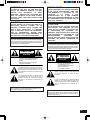
The lightning flash with arrowhead symbol, within
an equilateral triangle, is intended to alert the user
to the presence of uninsulated “dangerous voltage”
within the product’s enclosure that may be of suffi-
cient magnitude to constitute a risk of electric shock
to persons.
CAUTION
CAUTION: TO REDUCE THE RISK OF ELECTRIC
SHOCK, DO NOT REMOVE SCREWS.
NO USER-SERVICEABLE PARTS
INSIDE.
REFER SERVICING TO QUALIFIED
SERVICE PERSONNEL.
The exclamation point within an equilateral triangle
is intended to alert the user to the presence of
important operating and maintenance (servicing)
instructions in the literature accompanying the
appliance.
RISK OF ELECTRIC SHOCK
DO NOT OPEN
ATTENTION
RISQUE DE CHOC ELECTRIQUE
NE PAS OUVRIR
ATTENTION: AFIN DE PRÉVENIR LE RISQUE
DE CHOCS ÉLECTRIQUES, NE
PAS RETIRER LES VIS.
TOUTE RÉPARATION DEVRAIT
ÊTRE CONFIÉE À UN
PERSONNEL QUALIFIÉ.
Le point d’exclamation dans un triangle équilatéral
indique que le manuel d’utilisation inclus avec
l’appareil contient d’importantes recommandations
quant au fonctionnement et à l’entretien de ce
dernier.
Le symbole de l’éclair dans un triangle équilatéral
indique la présence d’une tension suffisamment
élevée pour engendrer un risque de chocs
électriques.
CAUTION (SB-FS70):
Do not stand on the base and shake the speaker. Be cau-
tious when children are near (see page 7).
ATTENTION (SB-FS70) :
Ne pas se tenir debout sur le socle ni secouer l’enceinte.
Surveiller de près les enfants lorsqu’ils s’approchent de
l’enceinte (voir page 7).

RQT7694
4
Read these operating instructions carefully before using the unit. Fol-
low the safety instructions on the unit and the applicable safety in-
structions listed below. Keep these operating instructions handy for
future reference.
1) Read these instructions.
2) Keep these instructions.
3) Heed all warnings.
4) Follow all instructions.
5) Do not use this apparatus near water.
6) Clean only with dry cloth.
7) Do not block any ventilation openings. Install in accordance with
the manufacturer’s instructions.
8) Do not install near any heat sources such as radiators, heat reg-
isters, stoves, or other apparatus (including amplifiers) that pro-
duce heat.
9) Do not defeat the safety purpose of the polarized or grounding-
type plug. A polarized plug has two blades with one wider than
the other. A grounding-type plug has two blades and a third
grounding prong. The wide blade or the third prong are provided
for your safety. If the provided plug does not fit into your outlet,
consult an electrician for replacement of the obsolete outlet.
10) Protect the power cord from being walked on or pinched particu-
larly at plugs, convenience receptacles, and the point where
they exit from the apparatus.
11) Only use attachments/accessories specified by the manufac-
turer.
12) Use only with the cart, stand, tripod, bracket, or
table specified by the manufacturer, or sold with
the apparatus. When a cart is used, use caution
when moving the cart/apparatus combination to
avoid injury from tip-over.
13) Unplug this apparatus during lightning storms or when unused
for long periods of time.
14) Refer all servicing to qualified service personnel. Servicing is
required when the apparatus has been damaged in any way,
such as power-supply cord or plug is damaged, liquid has been
spilled or objects have fallen into the apparatus, the apparatus
has been exposed to rain or moisture, does not operate normal-
ly, or has been dropped.
IMPORTANT SAFETY
INSTRUCTIONS
Avant d’utiliser l’appareil, lire attentivement le présent manuel. Porter
une attention toute particulière aux avis inscrits sur l’appareil et aux
instructions décrites ci-dessous. Conserver ce manuel pour
référence ultérieure.
1) Lire ces instructions.
2) Conserver ces instructions.
3) Respecter ces instructions.
4) Suivre toutes les instructions.
5) Ne pas utiliser cet appareil près de l’eau.
6) Nettoyer avec un chiffon sec seulement.
7) Ne pas bloquer les ouvertures pour ventilation. Installer selon
les directives du fabricant.
8) Éloigner l’appareil de toute source de chaleur telle que radia-
teurs et autres éléments de chauffage (incluant les amplifica-
teurs).
9) Ne pas tenter de contourner les mesures de sécurité des fiches
polarisées ou de mise à la terre. Une fiche polarisée possède
une lame plus large que l’autre. Une fiche avec mise à la terre
possède une troisième broche pour la mise à la terre. Si la fiche
ne peut pas être branchée, communiquer avec un électricien
pour faire changer la prise de courant.
10) Protéger le cordon secteur de manière qu’il ne soit pas piétiné
ou écrasé par des objets. Faire particulièrement attention à ses
extrémités de branchement, y compris sa fiche.
11) N’utiliser que les accessoires recommandés par le fabricant.
12) Ne placer l’appareil que dans une baie ou un
support recommandé par le fabricant. Déplacer
la baie ou le support avec le plus grand soin afin
d’en éviter le renversement.
13) Débrancher durant un orage ou lors de non-utilisation pro-
longée.
14) Confier toute réparation à un technicien qualifié. Faire réparer
l’appareil si le cordon ou la fiche a été endommagé, si l’appareil
a été mouillé, si un objet est tombé sur l’appareil, s’il a été ex-
posé à la pluie ou à de l’humidité, s’il ne fonctionne pas nor-
malement ou s’il a été échappé.
Précautions à prendre

RQT7694
5
270 mm
(10-5/8”)
(10 5/8 po)
30-35 mm
(1-3/16” to 1-3/8”)
(1 3/16 po à 1 3/8 po)
ø7.5-9.5 mm
7-9 mm
(9/32” to 23/64”)
(9/32 po à 23/64 po)
10 mm
(25/64”)
(25/64 po)
60 mm
(2-23/64”)
(2 23/64 po)
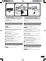
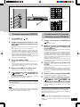
Speaker setup
Take care not to apply undue pressure to the front nets when han-
dling the speakers. Lay the speakers on a flat surface over a soft
cloth when working on them.
Tighten the screws firmly.
Center speaker (SB-PC70)
Place above or below the center of the television, on a shelf or rack or
attach to the wall. Placing it directly on the television can cause the
picture to be distorted.
Do not attach this speaker to walls or ceilings using methods other
than those described here.
Attaching the rubber feet when placing on a surface
Attach the rubber feet to the base of the speaker to prevent vibration
from causing the speaker to move or fall over.
Attaching to a wall
Attach four rubber feet to the rear of the speaker.
Screw (not included)
Screw the wood screw into a thick and hard part of the wall.
The surface must be able to support over 10 kg (22 lb.).
Attaching to a television stand
Ensure the following conditions are met when purchasing or prepar-
ing your television stand.
Observe the diameter and length of the screws and the distance be-
tween the screws as shown in the diagram.
Television stand (not included)
Screw (not included); diameter: 5 mm, pitch: 0.8 mm, length:
thickness of board plus 10 mm.
Distance between the centers of the holes: 60 mm.
The stand must be able to support over 10 kg (22 lb.).
Subwoofer (SB-WA70)
Place anywhere as long as it is a reasonable distance from the televi-
sion. Place it at least 5 cm (2w) from the wall as it has a bass reflex
port in the rear.
Do not attach the subwoofer to walls or ceilings.
Installation des enceintes
Prendre garde à ne pas exercer une pression indue sur les grilles des
enceintes. Coucher les enceintes sur une surface plane recouverte
d’un tissu doux.
Visser fermement.
Enceinte de canal centre (SB-PC70)
Placer l’enceinte au-dessus ou sous le téléviseur, centrée par rapport
à l’écran, ou encore sur une étagère, dans une baie ou fixée au mur.
Éviter de placer l’enceinte directement sur le téléviseur ; cela pourrait
entraîner une distorsion de l’image.
Ne pas fixer cette enceinte à un mur ou la suspendre par des méthodes
autres que celles décrites dans le présent manuel.
Fixation des pieds en caoutchouc lorsque l’enceinte
est posée sur une surface
Fixer les pieds en caoutchouc à la base de l’enceinte afin d’empêcher
que la vibration ne la déplace ou la fasse tomber.
Fixation à un mur
Fixer les quatre pieds en caoutchouc sur la paroi arrière de l’enceinte.
Vis (vendue séparément)
Insérer une vis à bois dans une section épaisse et résistante du mur.
La paroi murale doit pouvoir supporter plus de 10 kg (22 lb).
Fixation à un porte-téléviseur
Vérifier que les conditions suivantes sont satisfaites au moment de
l’achat ou de la préparation du porte-téléviseur.
Utiliser des vis du diamètre et de la longueur indiqués et respecter la
distance recommandée entre les vis (voir ci-après).
Porte-téléviseur (vendu séparément)
Vis (vendues séparément) ; diamètre : 5 mm ; pas : 0,8 mm ;
longueur : épaisseur de la planche plus 10 mm.
Distance entre le centre des trous : 60 mm.
Le porte-téléviseur doit pouvoir supporter plus de 10 kg (22 lb).
Enceinte d’extrêmes-graves (SB-WA70)
Il est possible de placer cette enceinte presque n’importe où à la con-
dition qu’elle soit à une distance raisonnable du téléviseur. La placer
à une distance d’au moins 5 cm (2 po) du mur en raison de la présence
d’un évent acoustique à l’arrière.
Ne pas fixer cette enceinte à un mur ou la suspendre au plafond.

RQT7694
6
Installation des enceintes
Enceintes avant et ambiophoniques (SB-FS70)
Les 4 enceintes sont identiques.
Positionner les enceintes avant de chaque côté du téléviseur. Placer
les enceintes ambiophoniques de chaque côté de la position d’écoute
ou légèrement derrière.
Ne pas fixer cette enceinte à un mur ou la suspendre
par des méthodes autres que celles décrites dans le
présent manuel.
Fixation du stabilisateur assemblé et du socle
(fournis)
Placer l’enceinte face contre le sol.
Vérifier que le stabilisateur assemblé est inclus dans l’emballage.
Stabilisateur Vis de fixation du stabilisateur
Cale
Connecter le câble d’enceinte (inclus) à la borne de l’enceinte
et le faire passer dans le trou du stabilisateur pour l’amener
jusqu’au socle.
•Câble pour enceintes ambiophoniques : environ 10 m (32,8 pi)
Câble pour les enceintes avant : environ 4 m (13,1 pi)
•Pour de plus amples détails sur les connexions des enceintes, se
reporter à la section “Raccordements” ( page 8)
Après avoir décidé de la hauteur de l’enceinte et avoir ajusté
la longueur du câble d’enceinte, fixer le stabilisateur assemblé
à l’enceinte au moyen des deux vis de fixation fournies.
Plage d’ajustement de la hauteur des enceintes ( ci-dessous)
Nota Veiller à ce que le câble ne soit pas coincé entre le
stabilisateur et l’enceinte.
Ajuster la longueur du câble d’enceinte et fixer le socle au
stabilisateur assemblé au moyen des deux vis de fixation
fournies.
Insérer le câble dans la rainure du câble d’enceinte sous le
fond du socle .
Ajustement de la hauteur
Après l’étape 3 ci-dessus, retirer le câble du côté de l’enceinte.
Desserrer suffisamment les deux vis de fixation du
stabilisateur pour permettre l’ajustement du panneau.
Ne pas trop desserrer les vis ; autrement, l’enceinte pourrait tomber.
Après avoir ajusté la hauteur de l’enceinte et la longueur du
câble, resserrer les deux vis de fixation du stabilisateur.
Plage de réglage : environ 1104 mm à 1390 mm (43 15/32 po à 54 3/4 po)
Nota Veiller à ce que le câble ne soit pas coincé entre le
stabilisateur et l’enceinte.
Faire cheminer le câble dans la rainure sur le socle
(étape 4 ci-dessus)
Fixation d’un câble de stabilisation
Exemple Collier en nylon Vis pour collier en nylon
Câble (vendu séparément)
Anneau (vendu séparément)
Vis (vendue séparément)
Insérer une vis à bois dans une section épaisse et résistante du mur.
La paroi murale doit pouvoir supporter plus de 40 kg (88 lb).
Fixation à un mur
Fixer les quatre pieds en caoutchouc (fournis) sur la paroi arrière de
l’enceinte, en s’assurant que deux font contact avec le mur et deux
sont sur les trous de fixation du stabilisateur assemblé.
Vis (vendue séparément)
Insérer une vis à bois dans une section épaisse et résistante du mur.
La paroi murale doit pouvoir supporter plus de 18 kg (39,6 lb).
30-35 mm
(1-3/16” to 1-3/8”)
(1 3/16 po à 1 3/8 po)
ø7.5-9.5 mm
7-9 mm
(9/32” to 23/64”)
(9/32 po à 23/64 po)
35 mm
(1-3/8”)
(1 3/8 po)
750 mm
(29-35/64”)
(29 35/64 po)
1390 mm
1104 mm
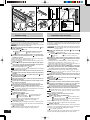
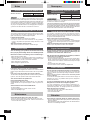
Speaker setup
Front and surround speakers (SB-FS70)
The 4 speakers are the same.
Put the front speakers either side of the television. Put the surround
speakers to the side of or slightly behind the seating area.
Do not attach this speaker to walls or ceilings using methods
other than those described here.
Attaching the assembled stabilizer (included) and
base (included)
Place the speaker facing down.
Confirm you have the Assembled Stabilizer (included).
Stabilizer Stabilizer attachment screws
Spacer
Connect the speaker cable (included) to the speaker termi-
nals and run the cable through the hole on the assembled
stabilizer to the base.
•Speaker cable for the surround speakers : Approx. 10 m (32.8 ft)
For the front speakers: Approx. 4 m (13.1 ft)
•For more information on speaker terminal connections refer to “Con-
nections” ( page 8)
After deciding on the speaker height and adjusting the speaker
cable length, attach the assembled stabilizer to the speaker
using the two stabilizer attachment screws.
Speaker height adjustable range ( below)
Note Do not get the speaker cable caught between the assembled
stabilizer and the speaker.
Adjust the speaker cable length and using the two base at-
tachment screws (included), fasten the base to the assembled
stabilizer.
Insert the speaker cable in the speaker cable groove on the
bottom side of the base .
Adjusting the height
After step 3 indicated above, pull out the speaker cable on the
speaker terminal side.
Loosen the two stabilizer attachment screws enough so that
the panel can be adjusted.
The speaker may fall off if you loosen the screws too much.
After adjusting the speaker height and the length of the cable,
securely fasten the two stabilizer attachment screws.
Adjustable range: Approx. 1104-1390 mm (43-15/32˝ to 54-3/4˝)
Note Do not get the speaker cable caught between the assembled
stabilizer and the speaker.
Fit the speaker cable in the groove in the base.
(Indicated above in step 4)
Attaching a stabilizing wire
Example Nylon clamp Screw for nylon clamp
Wire (not included) Ring (not included)
Screw (not included)
Screw the wood screw into a thick and hard part of the wall.
The surface must be able to support over 40 kg (88 lb.).
Attaching to a wall
Place the rubber pads (included) in four places on the back of the
speaker where it contacts the wall, and on the two attachment holes
for the assembled stabilizer.
Screw (not included)
Screw the wood screw into a thick and hard part of the wall.
The surface must be able to support over 18 kg (39.6 lb.).

RQT7694
7
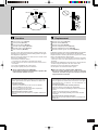
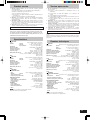
Location
Front speaker (Left) (SB-FS70)
Center speaker (SB-PC70)
Front speaker (Right) (SB-FS70)
Surround speaker (Right) (SB-FS70)
Surround speaker (Left) (SB-FS70)
Active subwoofer (SB-WA70)
The front, center, and surround speakers should be placed at ap-
proximately the same distance from the listening position. The angles
in the diagram are approximate.
How you set up your speakers can affect the bass and the sound
field. Note the following points.
•Place on flat, level secure surface.
Use spacers or a similar item to stop them from rocking.
•Placing speakers too close to walls, and corners can result in ex-
cessive bass.
•Cover walls and windows with a thick curtain.
•Do not place anything on top of the subwoofer.
Usage and handling note (SB-FS70):
Do not stand on the base and shake the speaker. Be
cautious when children are near.
Emplacement
Enceinte avant gauche (SB-FS70)
Enceinte centrale (SB-PC70)
Enceinte avant droite (SB-FS70)
Enceinte ambiophonique droite (SB-FS70)
Enceinte ambiophonique gauche (SB-FS70)
Enceinte d’extrêmes-graves avec ampli (SB-WA70)
Positionner les enceintes avant, centre et ambiophoniques à une distance
égale de la position d’écoute. Les angles illustrés sont approximatifs.
L’emplacement des enceintes peut affecter les graves et le champ
sonore. Lire attentivement les points suivants.
•Placer les enceintes sur une surface plate, de niveau et sécuritaire.
Utiliser des cales ou un objet similaire pour éviter qu’elles ne
basculent.
•Afin d’éviter une production excessive des graves, ne pas placer les
enceintes trop près du plancher, des murs ou des coins.
•Recouvrir les murs et les fenêtres d’un rideau épais.
•Ne rien placer sur l’enceinte d’extrêmes-graves.
Nota sur l’usage et la manipulation (SB-FS70) :
Ne pas se tenir debout sur le socle ni secouer
l’enceinte. Surveiller de près les enfants lorsqu’ils
s’approchent de l’enceinte.
30°
120°
30°
SB-PC70
SB-FS70 SB-FS70
SB-FS70SB-FS70
SB-WA70
Protection circuitry (SB-WA70)
This circuitry prevents damage caused by excessive input or ab-
normal signals. When excess input is detected, the sound is auto-
matically interrupted.
If sound is interrupted...
1. Reduce the volume level from the receiver or amplifier.
2. Press [POWER] to turn the unit off.
3. Check the sound source and connections for problems.
4. Press [POWER] to turn the unit on.
After the protection circuitry is reset...
Take care not to increase the receiver’s or amplifier’s volume level
too much.
Circuit de protection (SB-WA70)
Ce circuit protège l’enceinte contre tout dommage que pourrait
causer un signal excessivement élevé ou anormal. Si un signal
excessivement élevé est détecté, son acheminement est
automatiquement coupé.
En cas de déclenchement du circuit de protection…
1. Baisser le volume sur le récepteur ou l’amplificateur.
2. Appuyer sur l’interrupteur [POWER] pour mettre l’enceinte hors
marche.
3. Vérifier la source du signal et les raccordements.
4. Appuyer sur l’interrupteur [POWER] pour remettre l’enceinte
en marche.
Après réarmement du circuit de protection…
Prendre soin à ne pas trop monter le volume sur le récepteur ou
l’amplificateur.

RQT7694
8
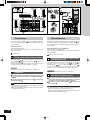
Connections
Connect to a receiver or amplifier with 6-Ω impedance for the front,
center, and surround speakers, and a pin-type output terminal for an
active subwoofer.
Before connection
Turn off the other equipment.
Do not connect the AC power supply cord until all other cables and
cords are connected.
Twist off the tip.
Front, center, and surround speakers
Connect the front and center speakers with the 4-meter
(13.1 ft) cables and the surround speakers with the 10-
meter (32.8 ft) cables .
Be sure to connect only positive (copper) wires to positive (+) termi-
nals and negative (silver) wires to negative (-) terminals.
Never short-circuit positive (+) and negative (-) speaker wires.
Subwoofer
Connect with the included monaural connection cable
to the receiver or amplifier’s subwoofer output ter-
minal.
Connect the AC power supply cord to the house-
hold AC outlet .
Note
•Do not move the speaker while the speaker cables are connected.
This may cause a short circuit.
•Make sure to bundle the speaker cable with a string etc. when re-
locating the speaker cables.
Raccordements
Raccorder les enceintes à un récepteur ou à un amplificateur sous
une impédance de 6 ohms pour les éléments des canaux avant, cen-
tre et ambiophoniques. Raccorder l’enceinte d’extrêmes-graves à
une prise à tige.
Avant d’effectuer les raccordements
Couper le contact sur l’équipement.
Ne pas brancher le cordon d’alimentation avant d’avoir effectué tous
les raccordements.
Retirer la pointe en la tordant.
Enceintes des canaux avant, centre
et ambiophoniques
Raccorder les enceintes des canaux avant et centre au
moyen des câbles de 4 mètres (13,1 pi) et les enceintes
ambiophoniques avec les câbles de 10 mètres (32,8 pi) .
S’assurer de ne raccorder que les fils positifs (cuivre) aux bornes
positives (+) et les fils négatifs (argent) aux bornes négatives (-).
Ne jamais court-circuiter les fils positifs (+) et négatifs (-).
Enceinte d’extrêmes-graves
Raccorder l’enceinte à la prise de sortie d’extrêmes-
graves du récepteur ou de l’amplificateur au moyen
du câble de raccordement monaural
fourni.
Brancher le cordon d’alimentation dans une prise
de courant .
Nota
•Toujours débrancher les câbles des enceintes avant de déplacer
l’enceinte ; cela prévient les risques de court-circuit.
•Enrouler et retenir la longueur excessive de câble au moyen d’une
ficelle lors du déplacement de l’enceinte.
SB-PC70
SB-PC70
SB-FS70 SB-FS70 SB-FS70
SB-WA70
SB-FS70SB-FS70

RQT7694
9
Subwoofer operation (SB-WA70)
1 Set [POWER] to “ ON”.
The indicator turns green.
2 Output sound from the receiver or am-
plifier and adjust the volume to a suit-
able level.
See the operating instructions for the other equipment for de-
tails.
Do not adjust the bass as this can cause distortion.
If the amplifier volume is switched to “0” (lowest setting), and it
is left in this position for longer than 8 minutes the unit auto-
matically switches to standby and the indicator turns red. Turn-
ing the amplifier volume up will automatically switch the unit to
operation mode, and the indicator turns green.
However, the subwoofer may not switch to standby due to noise
emitted by the connected amplifier.
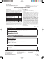
3 Set [LOW PASS FILTER].
Set the low pass filter on your receiver or amplifier to 200 Hz if
possible.
Refer to “Frequency response by LOW PASS FILTER setting”.
Set [LOW PASS FILTER] to 200 Hz for a full range. Reduce it if
you feel the bass is too strong.
4 Adjust [VOLUME] to a suitable level.
Refer to “Frequency response by VOLUME setting”.
5 Play something, then set [PHASE] to
“ NORMAL” or “ REVERSE” so
sound is normal.
The subwoofer and speakers cancel each other out (causing
unusual, muffled sound) if phase is incorrect.
When settings are complete
The only operation you should have to perform daily is press [POWER]
to turn the unit ON/OFF.
If you reposition the system and the acoustics change, reset the unit
as necessary.
Note
If the volume output is too loud, this unit’s amplifier can be clipped,
causing output to sound unusual. Reduce the volume of the receiver
or amplifier or the volume of this unit if this occurs.
20
10 dB
Sound pressure level
Niveau de pression acoustique
50 100 200 500 1000 (Hz)
200
150
100
80
60
50
(approximate values)
(valeurs approximatives)
(approximate values)
(valeurs approximatives)
20
10 dB
Sound pressure level
Niveau de pression acoustique
50 100 200 500 1000 (Hz)
LOW PASS FILTER : 200 Hz(max)
FILTRE PASSE-BAS : 200 Hz(max)
(max)
Frequency response by LOW PASS FILTER setting
Réponse en fréquence et réglage du filtre passe-bas
Frequency response by VOLUME setting
Réponse en fréquence et volume
Fonctionnement de l’enceinte
d’extrêmes-graves (SB-WA70)
1 Régler l’interrupteur [POWER] sur
“ ON”.
Le voyant s’allume en vert.
2 Mettre le récepteur ou l’amplificateur en
marche et régler le volume à un
niveau adéquat.
Pour plus de détails, se rapporter au manuel de l’utilisateur du
récepteur ou de l’amplificateur.
Ne pas régler le niveau des graves ; cela pourrait causer de la distorsion.
Si le volume sur l’amplificateur est à “0” (réglage le plus bas)
pendant plus de 8 minutes, l’enceinte passe automatiquement
au mode attente et le voyant s’allume en rouge. Augmenter le
volume sur l’amplificateur met automatiquement l’enceinte en
fonction et le voyant s’allume en vert.
Cependant, l’enceinte d’extrêmes-graves peut ne pas passer
au mode attente en raison du bruit généré par l’amplificateur
ou le récepteur raccordé.
3 Régler le filtre passe-bas [LOW PASS
FILTER]
Si possible, régler le filtre passe-bas du récepteur ou de
l’amplificateur à 200 Hz.
Voir le diagramme “Réponse en fréquence et réglage du filtre
passe-bas”. Pour une réponse étendue, régler le filtre passe-
bas à 200 Hz. La réduire si la réponse dans les graves semble
trop accentuée.
4
Régler le volume au moyen de [VOLUME].
Voir le diagramme “Réponse en fréquence et volume”.
5
Lancer la lecture d’une pièce musicale,
puis régler la commade [PHASE] sur
“ NORMAL” ou “ REVERSE” de
manière que le rendu sonore soit normal.
En cas de déphasage, l’enceinte d’extrêmes-graves et les autres
s’annulent mutuellement engendrant ainsi un son étouffé,
inhabituel.
Après avoir effectué les réglages
La seule opération à faire régulièrement se limitera à appuyer sur
l’interrupteur [POWER] pour mettre l’enceinte en et hors marche.
Si l’emplacement des enceintes est modifié et que l’acoustique est
différente, régler à nouveau l’enceinte.
Nota
Si le volume est trop élevé, l’amplificateur de l’enceinte d’extrêmes-
graves pourrait subir un écrêtage, engendrant un rendu sonore
anormal. Le cas échéant, baisser le volume sur le récepteur ou
l’amplificateur.

RQT7694
10
Notes
Speaker impedance and allowed input
SB-FS70 / SB-PC70 Impedance 6 Ω
Input power 100 W (RATED)
The only receivers or amplifiers you should connect to these speak-
ers are those whose rated output does not exceed the above figures.
Using a receiver or amplifier with higher ratings than listed above can
cause abnormal sounds to occur because of excessive input, dam-
age to the receiver or speakers, and fire. If equipment is damaged in
any way or unexpected trouble occurs during playback, unplug the
system from its outlet and call a servicenter for assistance.
Protection circuitry
(SB-FS70 / SB-PC70)
These units incorporate protection circuitry to protect them from dam-
age caused by excessive input or abnormal signals; when excess
input is detected, input is automatically interrupted.
If sound is interrupted...
1.Reduce the volume of the receiver (or amplifier).
2.Check the sound source and connections for any problems.
If there is no problem, the protection circuitry will reset in a few
minutes.
After the protection circuit is reset...
Take care not to increase the receiver’s volume too high.
Excessive input
You can damage your speakers and shorten their useful
life if you play sound at high levels over extended periods.
Reduce the volume in the following cases to avoid damage :
•When playing distorted sound.
•When the speakers are receiving howling from a microphone or
record player, noise from FM broadcasts, or continuous signals
from an oscillator, test disc, or electronic instrument.
•When adjusting the sound quality.
•When turning the amplifier on or off.
Other notes
If irregular coloring occurs on your television :
These speakers are designed to be used close to a television, but the
picture may be affected with some televisions and set-up combina-
tions.
If this occurs, turn the television off for about 30 minutes.
The television’s demagnetizing function should correct the problem. If
it persists, move the speakers further away from the television.
You cannot remove the speaker net.
Keep magnetized items away.
Magnetized cards, bank cards, commuter passes, etc., can be dam-
aged if allowed too near speaker magnets. Clocks may also be af-
fected.
Avoid locations such as described below :
•In direct sunlight
•Near heating appliances or other sources of heat
•Where the humidity is high
Maintenance
Clean these units with a soft, clean, dry cloth.
•Never use alcohol, paint thinner, or benzine to clean these units.
•Before using chemically treated cloth, read the instructions that
came with the cloth carefully.
Remarques
Impédance des enceintes et puis-
sance admissible
SB-FS70 / SB-PC70 Impédance 6 Ω
Puissance admissible
100 W (nominale)
Seuls les amplificateurs ou récepteurs dont la puissance de sortie
nominale ne dépasse pas celle donnée ci-dessus doivent être
raccordés aux enceintes acoustiques.
L’utilisation d’un amplificateur ou d’un récepteur plus puissant pourrait produire
des sons anormaux en raison d’entrée excessif, endommager les enceintes
ou le récepteur ou déclencher un incendie. Dans l’éventualité d’un mauvais
fonctionnement des appareils ou si ceux-ci sont endommagés, les débrancher
de la prise de courant et contacter un centre de service agréé.
Circuit de protection (SB-FS70 / SB-PC70)
Les enceintes sont munies de circuits les protégeant contre les
dommages que peuvent causer un signal d’entrée trop élevé ou
anormal ; lorsqu’un signal trop intense est détecté, l’acheminement
du signal est automatiquement coupé.
Dans le cas où le son est interrompu…
1.Baisser le volume sur le récepteur ou l’amplificateur.
2.Vérifier la source sonore et les raccordements. Si aucun problème
n’est détecté, le circuit de protection sera réarmé dans quelques
minutes.
Suite au réarmement du circuit de protection…
Veiller à ne pas trop monter le volume sur le récepteur.
Signal d’entrée excessif
Ne pas effectuer d’écoute à un niveau élevé pendant une
période prolongée car cela pourrait endommager les
enceintes et en réduire leur durée de vie.
Afin de prévenir tout dommage aux enceintes, réduire le
volume dans les conditions suivantes :
•Lors de l’écoute avec distorsion.
•Lors de la réception de sifflement à cause d’un micro ou d’un tourne-
disque, d’émissions FM avec interférence, ou de signaux continus
en provenance d’un oscillateur, instrument électrique ou disque
d’essai.
•Lors du réglage de la qualité sonore.
•Lors de la mise en ou hors contact de l’amplificateur.
Autres remarques
En cas de rendu chromatique irrégulier sur le téléviseur :
Ces enceintes ont été conçues pour être placées à proximité d’un
téléviseur ; toutefois, il peut arriver que I’image soit affectée sur certains
téléviseurs.
Dans un tel cas, couper le contact sur le téléviseur pendant
environ 30 minutes.
La fonction de démagnétisation du téléviseur devrait corriger le
problème. Par contre, si le problème devait persister, éloigner les
enceintes du téléviseur.
Il n’est pas possible de retirer la grille des enceintes.
Éloigner les enceintes de tout objet magnétisé.
Les cartes magnétiques, cartes de guichet automatique, etc.,
pourraient être endommagées si elles sont placées à proximité de
l’aimant d’un haut-parleur. Les horloges peuvent aussi être affectées.
Éviter de placer les enceintes :
•Dans un endroit exposé aux rayons solaires directs ;
•Près d’une source de chaleur ;
•Dans un endroit humide.
Entretien
Pour nettoyer l’appareil, utiliser un chiffon doux et sec.
•Ne jamais utiliser d’alcool, diluant pour peinture ni de benzène pour
nettoyer l’appareil.
•Avant d’utiliser un chiffon traité chimiquement, lire attentivement les
directives sur l’emballage du chiffon.

RQT7694
11
Product service
1. Damage requiring service—The unit should be serviced by qualified
service personnel if:
(a) The AC power supply cord or AC adaptor has been damaged; or
(b) Objects or liquids have gotten into the unit; or
(c) The unit has been exposed to rain; or
(d) The unit does not operate normally or exhibits a marked change in
performance; or
(e) The unit has been dropped, or the cabinet damaged.
2. Servicing—Do not attempt to service the unit beyond that described in
these operating instructions. Refer all other servicing to authorized
servicing personnel.
3. Replacement parts—When parts need replacing ensure the servicer
uses parts specified by the manufacturer or parts that have the same
characteristics as the original parts. Unauthorized substitutes may result
in fire, electric shock, or other hazards.
4. Safety check—After repairs or service, ask the servicer to perform safety
checks to confirm that the unit is in proper working condition.
Product information
For product information or assistance with product operation:
In the U.S.A., refer to “Customer Services Directory” on back cover.
In Canada, contact the Panasonic Canada Inc. Customer Care Cen-
tre at 905-624-5505, or visit the website (www.panasonic.ca), or an
authorized Servicentre closest to you.
Specifications
SB-FS70
Type 3 way 4 speaker system Closed type
Speaker Woofer: 8 cm (3-1/8w) cone type x 2
Tweeter: 2.5 cm (1w) semi-dome type x 1
Super Tweeter: 1.2 cm (1/2w) dome type x 1
Impedance 6 Ω
Input power (IEC) 200 W (MAX), 100 W (RATED)
Sound pressure level 81 dB/W (1.0 m)
Crossover frequency 2.7 kHz, 20 kHz
Frequency range 140 Hz – 100 kHz (at –16 dB)
180 Hz – 90 kHz (at –10 dB)
Dimensions (W x H x D) 262 x 1104 (MIN) – 1390 (MAX) x 264 mm
(10-5/16w x 43-15/32w(MIN) – 54-3/4w(MAX) x 10-3/8w)
(with the stand)
Mass 8.0 kg (17.6 lb.)
SB-PC70
Type 3 way 5 speaker system Bass-reflex type
Speaker Woofer: 5 cm (2w) cone type x 4
Tweeter: 2.5 cm (1w) semi-dome type x 1
Impedance 6 Ω
Input power (IEC) 200 W (MAX), 100 W (RATED)
Sound pressure level 82 dB/W (1.0 m)
Crossover frequency 3.5 kHz, 4.5 kHz
Frequency range 130 Hz – 50 kHz (at –16 dB)
150 Hz – 45 kHz (at –10 dB)
Dimensions (W x H x D) 430 x 64 x 100 mm
(16-15/16w x 2-17/32w x 3-15/16w)
Mass 1.8 kg (4.0 lb.)
SB-WA70
SPEAKER SECTION
Type 1 way 1 speaker system Bass-reflex type
Speaker Woofer: 17 cm (6-3/4w) cone type x 1
Sound pressure level 80 dB/W (1.0 m)
Frequency range (with amp) 32 – 300 Hz (at –16 dB)
38 – 240 Hz (at –10 dB)
AMPLIFIER SECTION
Output power 100 W (6 Ω) (THD 0.9%)
Input sensitivity / Input Impedance 300 mV/33 kΩ (RCA jack)
Phase switching NORMAL/REVERSE
Low pass filter 50 – 200 Hz Variable
GENERAL
Power supply AC 120 V, 60 Hz
Power consumption 168 W
Dimensions (W x H x D) 162 x 457 x 420 mm
(6-13/32w x 18w x 16-9/16w)
Mass 10.8 kg (23.8 lb.)
Specifications are subject to change without notice.
Mass and dimensions are approximate.
Service après-vente
1. En cas de dommage—Confier l’appareil à un technicien qualifié dans
les cas suivants:
(a) lorsque le cordon d’alimentation ou l’adaptateur secteur a été
endommagé;
(b) lorsqu’un objet est tombé dans l’appareil ou si ce dernier a été
mouillé;
(c) lorsque l’appareil a été exposé à la pluie;
(d) lorsque l’appareil semble ne pas fonctionner normalement ou que son
rendement laisse à désirer;
(e) lorsque l’appareil a subi un choc violent ou que son coffret a été
endommagé.
2. Réparation—Ne faire aucun réglage ni ajustement autres que ceux
décrits dans le présent manuel. Confier toute réparation à un centre de
service Panasonic agréé.
3. Pièces de rechange—S’assurer que le technicien utilise des pièces de
rechange recommandées par le fabricant ou dont les caractéristiques
sont les mêmes. L’utilisation de pièces de rechange non autorisées peut
causer un incendie, des chocs électriques ou d’autres dangers.
4. Vérification de sécurité—Demander au technicien qui a réparé
l’appareil de soumettre ce dernier à des vérifications pour s’assurer qu’il
peut être utilisé en toute sécurité.
Demande d’informations
Pour toutes réparations, renseignements ou conseils sur le fonctionnement du
produit:
Veuillez contacter le service à la clientèle de Panasonic Canada Inc. au 905-
624-5505, son site web (www.panasonic.ca) ou le centre de service agréé le
plus proche.
Données techniques
SB-FS70
Type Enceinte 3 voies à 4 haut-parleurs (type fermé)
Haut-parleur Graves : 8 cm (3 1/8 po) à cône x 2
Aigus : 2,5 cm (1
po) à semi-dôme x 1
Ultra aigus: 1,2 cm (1/2 po) à dôme x 1
Impédance 6 ohms
Puissance admissible (IEC) 200 W (MAX), 100 W (nominale)
Niveau de pression acoustique 81 dB/W (1,0 m)
Fréquence de recouvrement 2,7 kHz, 20 kHz
Réponse en fréquence 140 Hz – 100 kHz (à –16 dB)
180 Hz – 90 kHz (à –10 dB)
Dimensions (L x H x P) 262 x 1104 (MIN) – 1390 (MAX) x 264 mm
(10 5/16
po x 43 15/32
po (MIN) – 54 3/4
po (MAX) x 10 3/8
po)
(socle compris)
Poids 8,0 kg (17,6 lb)
SB-PC70
Type Enceinte 3 voies à 5 haut-parleurs (évent réflex)
Haut-parleur Graves : 5 cm (2 po) à cône x 4
Aigus : 2,5 cm (1
po) à semi-dôme x 1
Impédance 6 ohms
Puissance admissible (IEC) 200 W (MAX), 100 W (nominale)
Niveau de pression acoustique 82 dB/W (1,0 m)
Fréquence de recouvrement 3,5 kHz, 4,5 kHz
Réponse en fréquence 130 Hz – 50 kHz (à –16 dB)
150 Hz – 45 kHz (à –10 dB)
Dimensions (L x H x P) 430 mm x 64 mm x 100 mm
(16 15/16
po x 2 17/32
po x 3 15/16
po)
Poids 1,8 kg (4,0 lb)
SB-WA70
SECTION HAUT-PARLEUR
Type Enceinte 1 voie à 1 haut-parleur (évent réflex)
Haut-parleur Graves : 17 cm (6 3/4 po) à cône x 1
Niveau de pression acoustique 80 dB/W (1,0 m)
Réponse en fréquence (avec ampli) 32 Hz – 300 Hz (à –16 dB)
38 Hz – 240 Hz (à –10 dB)
SECTION AMPLIFICATEUR
Puissance de sortie 100 W (6 ohms) (D.H.T. : 0,9 %)
Sensibilité / impédance d’entrée 300 mV/33 kilohms (prise RCA)
Commutation de phase NORMAL/REVERSE
Filtre passe-bas 50 Hz – 200 Hz (variable)
GÉNÉRALITÉS
Alimentation 120 c.a., 60 Hz
Consommation 168 W
Dimensions (L x H x P) 162 mm x 457 mm x 420 mm
(6 13/32 po x 18 po x 16 9/16 po)
Poids 10,8 kg (23,8 lb)
Données sous réserve de modifications.
Le poids et les dimensions sont approximatifs.

RQT7694-Y
M0304TK0
CfEn
Panasonic Sales Company,
Division of Matsushita Electric of
Puerto Rico, Inc. (“PSC”)
Ave. 65 de Infantería, Km. 9.5
San Gabriel Industrial Park, Carolina,
Puerto Rico 00985
Panasonic Canada Inc.
5770 Ambler Drive
Mississauga, Ontario L4W 2T3
www.panasonic.ca
Panasonic Consumer Electronics
Company, Division of Matsushita
Electric Corporation of America
One Panasonic Way Secaucus,
New Jersey 07094
http://www.panasonic.com
2004 Matsushita Electric Industrial Co., Ltd.
Printed in Malaysia / Imprimé en Malaisie
Customer Services Directory
Accessory Purchases
Obtain Product Information and Operating Assistance; locate your nearest Dealer or Servicenter; purchase Parts and
Accessories; or make Customer Service and Literature requests by visiting our Web Site at:
http://www.panasonic.com/support
or, contact us via the web at:
http://www.panasonic.com/contactinfo
You may also contact us directly at:
1-800-211-PANA (7262),
Monday-Friday 9 am-9 pm; Saturday-Sunday 10 am-7 pm, EST.
For hearing or speech impaired TTY users, TTY: 1-877-833-8855
Purchase Parts, Accessories and Instruction Books online for all Panasonic Products by visiting our Web Site at:
http://www.pasc.panasonic.comm
or, send your request by E-mail to:
You may also contact us directly at:
1-800-332-5368 (Phone) 1-800-237-9080 (Fax Only) (Monday – Friday 9 am to 8 pm, EST.)
Panasonic Services Company
20421 84th Avenue South, Kent, WA 98032
(We Accept Visa, MasterCard, Discover Card, American Express, and Personal Checks)
For hearing or speech impaired TTY users, TTY: 1-866-605-1277
Matsushita Electric of Puerto Rico, Inc. Panasonic Sales Company
Factory Servicenter:
Ave. 65 de Infantería, Km. 9.5, San Gabriel Industrial Park, Carolina, Puerto Rico 00985
Phone (787)750-4300, Fax (787)768-2910
Service in Puerto Rico
(ONLY FOR U.S.A.)
Panasonic/Technics Audio Products
Limited Warranty
Panasonic Consumer Electronics Company,
Division of Matsushita Electric Corporation of America
One Panasonic Way Secaucus, New Jersey 07094
Panasonic Sales Company, Division of Matsushita Electric
of Puerto Rico, Inc.,
Ave. 65 de Infantería, Km. 9.5
San Gabriel Industrial Park, Carolina, Puerto Rico 00985
Limited Warranty Coverage
If your product does not work properly because of a defect in materials or workmanship,
Panasonic Consumer Electronics Company or Panasonic Sales Company (collectively
referred to as “the warrantor”) will, for the length of the period indicated on the chart below,
which starts with the date of original purchase (“warranty period”), at its option either (a)
repair your product with new or refurbished parts, or (b) replace it with a new or a refur-
bished product. The decision to repair or replace will be made by the warrantor.
RQA0197 F1003
During the “Labor” warranty period there will be no charge for labor. During the “Parts”
warranty period, there will be no charge for parts. You must carry-in or mail-in your prod-
uct during the warranty period. If non-rechargeable batteries are included, they are not
warranted. This warranty only applies to products purchased and serviced in the United
States or Puerto Rico. This warranty is extended only to the original purchaser of a new
product which was not sold “as is”. A purchase receipt or other proof of the original pur-
chase date is required for warranty service.
Carry-In or Mail-In Service
For Carry-In or Mail-In Service in the United States call 1-800-211-PANA (1-800-211-
7262) or visit Panasonic web site: http://www.panasonic.com
For assistance in Puerto Rico call Panasonic Sales Company (787)-750-4300 or fax
(787)-768-2910.
Limited Warranty Limits And Exclusions
This warranty ONLY COVERS failures due to defects in materials or workmanship, and
DOES NOT COVER normal wear and tear or cosmetic damage. The warranty ALSO
DOES NOT COVER damages which occurred in shipment, or failures which are caused
by products not supplied by the warrantor, or failures which result from accidents, misuse,
abuse, neglect, mishandling, misapplication, alteration, faulty installation, set-up adjust-
ments, misadjustment of consumer controls, improper maintenance, power line surge,
lightning damage, modification, or commercial use (such as in a hotel, office, restaurant,
or other business), rental use of the product, service by anyone other than a Factory
Servicenter or other Authorized Servicer, or damage that is attributable to acts of God.
THERE ARE NO EXPRESS WARRANTIES EXCEPT AS LISTED UNDER “LIMITED
WARRANTY COVERAGE”. THE WARRANTOR IS NOT LIABLE FOR INCIDENTAL
OR CONSEQUENTIAL DAMAGES RESULTING FROM THE USE OF THIS PRODUCT,
OR ARISING OUT OF ANY BREACH OF THIS WARRANTY. (As examples, this ex-
cludes damages for lost time, travel to and from the servicer, loss of media or images,
data or other memory content. The items listed are not exclusive, but are for illustration
only.) ALL EXPRESS AND IMPLIED WARRANTIES, INCLUDING THE WARRANTY OF
MERCHANTABILITY, ARE LIMITED TO THE PERIOD OF THE LIMITED WARRANTY.
Some states do not allow the exclusion or limitation of incidental or consequential damages,
or limitations on how long an implied warranty lasts, so the exclusions may not apply to you.
This warranty gives you specific legal rights and you may also have other rights which
vary from state to state. If a problem with this product develops during or after the warran-
ty period, you may contact your dealer or Servicenter. If the problem is not handled to your
satisfaction, then write to the warrantor’s Consumer Affairs Department at the addresses
listed for the warrantor.
PARTS AND SERVICE WHICH ARE NOT COVERED BY THIS LIMITED WARRANTY
ARE YOUR RESPONSIBILITY.
Parts
One (1) year
Thirty (30) days
Three (3) years
One (1) year
Ninety (90) days
Ten (10) days
Ninety (90) days
Product or Part Name
Audio Products (except items listed below)
All Audio Racks (cabinets)
Technics Stand Alone Speakers, Subwoofer
Speakers
USB Reader-Writer, Personal Computer
Card Adapters
(in exchange for defective item)
Accessories: Headphones, Cartridges,
Microphones, Adapters
Rechargeable Batteries, DVD-R/-RAM Discs
(in exchange for defective item)
SD Memory Cards, Rechargeable Battery
Packs (in exchange for defective item)
Labor
One (1) year
Not Applicable
Three (3) years
Not Applicable
Ninety (90) days
Not Applicable
Not Applicable
(ONLY FOR U.S.A.)
-
 1
1
-
 2
2
-
 3
3
-
 4
4
-
 5
5
-
 6
6
-
 7
7
-
 8
8
-
 9
9
-
 10
10
-
 11
11
-
 12
12


Panasonic SB-TP70 Manuel utilisateur
- Catégorie
- Subwoofers
- Taper
- Manuel utilisateur
- Ce manuel convient également à
dans d''autres langues
- English: Panasonic SB-TP70 User manual
Documents connexes
-
Panasonic SB-PF500K Le manuel du propriétaire
-
-
-
-
-
-
-
-