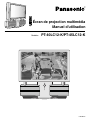
Panasonic PT40LC12K Mode d'emploi
- Catégorie
- Téléviseurs LCD
- Taper
- Mode d'emploi
Ce manuel convient également à

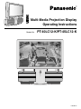
Models No. PT-40LC12-K/PT-45LC12-K
LSQT0615A
Multi-Media Projection Display
Operating Instructions

2
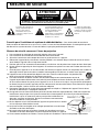
Important Safety Instructions
This symbol warns the user
that uninsulated voltage within
the unit may have sufficient
magnitude to cause electric
shock.
Therefore, it is dangerous to
make any kind of contact with
any inside part of this unit.
This symbol alerts the user that
important literature concerning
the operation and maintenance
of this unit has been included.
Therefore, it should be read
carefully in order to avoid any
problems.
The pictorial representation of
a hot surface within a triangle
is intended to tell the user that
parts inside the product are a
risk of burns to persons.
Note to CATV System Installer: This reminder is provided to call the CATV system installer’s attention to Article
820–40 of the NEC that provides guidelines for proper grounding and, in particular, specifies that the cable ground shall
be connected to the grounding system of the building, as close to the point of cable entry as practical.
Important Safety Instructions For Projection display
WARNING: To reduce the risk of electric shock, do not remove cover or back. No
user-serviceable parts inside. Refer servicing to qualified service personnel.
CAUTION
RISK OF ELECTRIC SHOCK
DO NOT OPEN
1. Read and apply the operating instructions provided with your projection display.
2. Read all of the instructions given here and retain them for later use.
3. Follow all warnings and instructions marked on the projection display.
4. Unplug this projection display from the wall outlet before cleaning. Do not use liquid or aerosol cleaners. Use a
damp cloth for cleaning.
5. Do not use attachments / accessories not recommended by the projection display manufacturer as they may cause
hazards.
6. Do not use this projection display near water. For example: Avoid placing it near a bathtub, washbowl, kitchen sink,
or laundry tub, in a wet basement, or near a swimming pool, etc.
7. Do not place this projection display on an unstable cart, stand or table. The projection display may fall,
causing serious injury to a child or adult, and serious damage to the appliance. Use only with a cart or
stand recommended by the manufacturer, or sold with the projection display.
7A. An appliance and cart combination shall be moved with care. Quick stops, excessive force, and uneven
surfaces may cause the appliance and cart combination to overturn.
8. Slots and openings in the cabinet and the back are provided for ventilation, to ensure reliable operation of the
projection display and to protect it from overheating. These openings must not be blocked or covered. There shall
be at least 10 cm of space from these openings. The openings shall never be blocked by placing the projection
display on a bed, sofa, rug or other similar surface. This projection display shall never be placed near or over a
radiator or heat register. This projection display shall not be placed in a built-in installation such as a bookcase
unless proper ventilation is provided.
9. Operate only from the type of power source indicated on the marking label. If you are not sure of the type of power
supplied to your home consult your television dealer or local power company.
10. This projection display is equipped with a polarized alternating-current line plug
(a plug having one blade wider than the other). This plug will fit into the power
outlet only one way. This is a safety feature. If you are unable to insert the plug
fully into the outlet, try reversing the plug. If the plug should still fail to fit, contact
your electrician to replace your obsolete outlet. Do not defeat the safety purpose
of the polarized plug.
11. Do not allow anything to rest and to pinch on the power cord. Do not locate this
projection display where the power cord will walked on.
12. Do not overload wall outlets and extension cords as this can result in fire or electric shock.
13. Never push objects of any kind into this projection display through cabinet slots as they may touch dangerous
voltage points or short out parts that could result in a fire or electric shock. Never spill liquid of any kind on the
projection display.

3
Getting Started
Important Safety Instructions
14. If an outside antenna is connected to the television equipment, be sure the antenna system is grounded so as to
provide some protection against voltage surges and built up static charges. In the U.S.Selection 810 of the National
Electrical Code provides information with respect to proper grounding of the mast and supporting structure,
grounding of the lead-in wire to an antenna discharge unit, size of grounding conductors, location of antenna-
discharge unit, connection to grounding electrodes, and requirements for the grounding electrode. See Figure.
15. For added protection for this projection display during a lightning storm, or when it is left unattended and unused for
long periods of time, unplug it from the wall outlet and disconnect the antenna. This will prevent damage to the
receiver due to lightning and power-line surges.
16. An outside antenna system shall not be located in the vicinity of overhead power lines or other electric light or
power circuits, or where it can fall into such power lines or circuits. When installing an outside antenna system
extreme care shall be taken to keep from touching such power lines or circuits as contact with them might be fatal.
17. Unplug this projection display from the wall outlet, and refer servicing to qualified service personnel under the
following conditions:
a. When the power cord or plug is damaged or frayed.
b. If liquid has been spilled into the projection display.
c. If the projection display has been exposed to rain or water.
d. If the projection display does not operate normally by following the operating instructions. Adjust only those
controls that are covered by the operating instructions as improper adjustment of other controls may result in
damage and will often require extensive work by a qualified technician to restore the projection display to normal
operation.
e. If the projection display has been dropped or the cabinet has been damaged.
f. When the projection display exhibits a distinct change in performance - this indicates a need for service.
18. Do not attempt to service this projection display yourself as opening or removing covers may expose you to
dangerous voltage or other hazards. Refer all servicing to qualified service personnel.
19. When replacement parts are required, be sure the service technician has used replacement parts specified by the
manufacturer that have the same characteristics as the original part. Unauthorized substitutions may result in fire,
electric shock, or other hazards.
20. Upon completion of any service or repairs to this projection display, ask the service technician to perform routine
safety checks to determine that the projection display is in safe operating condition.
21. WARNING: To prevent fire or shock hazard, do not expose this appliance to rain or moisture.
22. WARNING: Because the temperature of the lamp unit is elevated immediately after its use, directly touching it
may cause burns. After the lamp has cooled enough, replace the lamp unit.
23. CAUTION: To prevent electric shock, match wide blade of plug to wide slot of AC outlet and fully insert. Do not
use this (polarized) plug with a receptacle or other outlet unless the blade can be fully inserted to
prevent blade exposure.
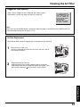
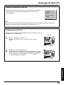
Clean the air filter regularly. Not cleaning the air filter could shorten the life of the set.
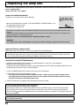
The lamp has a maximum life of about 5 000 hours.
If use exceeds this figure, the possibility of lamp damage becomes greater.
The lamp should be changed as soon as possible once the lamp warning message appears.
If the lamp is damaged, please contact your nearest dealer.
When VIEWING MODE is set to CINEMA, brightness will be reduced, but the life of the LCD panel can be
prolonged. Therefore, the CINEMA setting is recommended when possible.

4
Welcome to the Panasonic family of customers. We hope that you will have many years of enjoyment
from your new projection television set.
To obtain maximum benefit from your set, please read these Instructions before making any adjustments, and
retain them for future reference.
Retain your purchase receipt also, and record the serial number of your set in the space provided on
the rear cover of these instructions.
Trademarks
• Licensed by BBE Sound, Inc. under USP4638258 and 4482866. BBE and BBE symbol are registered trademarks of BBE
Sound, Inc.
• VGA and XGA are trademarks of International Business Machines Corporation.
• Macintosh is a registered trademark of Apple Computer, USA.
• VESA and SVGA are trademarks of the Video Electronics Standard Association.
Even if no special notation has been made of company or product trademarks, these trademarks have been fully respected.
• Equipped with
®
-TV Noise Reduction for true MTS reproduction.
®
-TV Noise Reduction is required for good stereo
separation and audio fidelity.
®
is a registered trademark, and is licensed by
®
Technology Licensing.
Dear Panasonic Customer

5
Getting Started
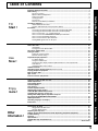
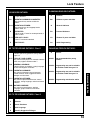
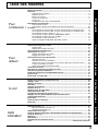
Table of Contents
Cleaning the Air Filter ................................................................................................................ 62
Clogged Air Filter Detection .............................................................................................. 63
Air Filter Replacement ...................................................................................................... 63
Replacing the lamp unit............................................................................................................. 64
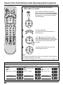
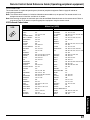
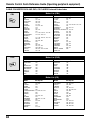
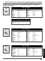
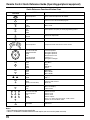
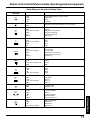
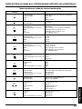
Remote Control Quick Reference Guide (Operating peripheral equipment)........................ 65
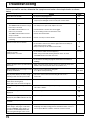
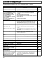
Troubleshooting ......................................................................................................................... 72
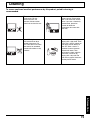
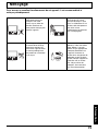
Cleaning ...................................................................................................................................... 73
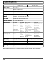
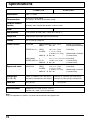
Specifications ............................................................................................................................. 74
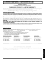
Limited Warranty / Servicentre List .......................................................................................... 75
Index .............................................................................................................................Back Cover
Important Safety Instructions ..................................................................................................... 2
Before Using ................................................................................................................................. 6
Receiver Location ...............................................................................................................6
Optional External Equipment .............................................................................................. 6
Safety Precaution ...............................................................................................................6
Viewing position .................................................................................................................. 6
Accessories ........................................................................................................................ 7
Remote Control Battery Installation .................................................................................... 7
Location of Controls .................................................................................................................... 8
Illuminated Remote Control ................................................................................................ 8
Controls and Terminals on the projection display ............................................................. 10
Installation .................................................................................................................................. 12
Connecting the Antenna/Cable to the RF In Terminal (No VCR) ...................................... 12
Connecting the Antenna/Cable to the RF In Terminal (VCR) ............................................ 14
How to connect the “1, 2, 3” Input Terminals .................................................................... 15
How to connect the COMPONENT VIDEO Input Terminals ............................................. 16
How to connect the AV Out Terminals .............................................................................. 17
How to connect the PC Input Terminals ............................................................................ 18
Analog RGB signals that can be input .............................................................................. 19
Adjusting screen position and size .......................................................................................... 40
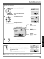
Audio Adjustments .................................................................................................................... 42
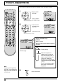
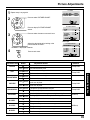
Picture Adjustments .................................................................................................................. 44
Closed Captions ......................................................................................................................... 46
Lock Feature ............................................................................................................................... 48
Channel Caption Feature........................................................................................................... 55
Weak Signal Display Feature .................................................................................................... 56
Video NR (Noise Reduction) Feature ....................................................................................... 57
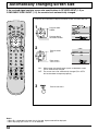
Automatically changing screen size ........................................................................................ 58
Setting when 480p signals (sequential scan) are
input through COMPONENT VIDEO INPUT ............................................................................. 59
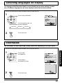
RGB Input Feature ..................................................................................................................... 60
Switching languages for display .............................................................................................. 61
Information ................................................................................................................................. 61
TO
Start !
Use
Now !
Enjoy
more !
Other
Information !
Advanced Operation
Information
Power ON / OFF .......................................................................................................................... 20
Initial Setup ....................................................................................................................... 20
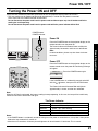
Turning the Power ON and OFF ....................................................................................... 21
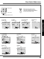
Flow Chart of Main menu .......................................................................................................... 22
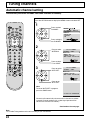
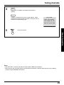
Tuning channels ......................................................................................................................... 24
Automatic channel setting ................................................................................................. 24
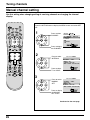
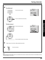
Manual channel setting ..................................................................................................... 26
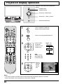
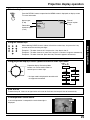
Projection display operation ..................................................................................................... 28
TV Status display .............................................................................................................. 29
Using the number keys ..................................................................................................... 29
Using projection display Channel up/down buttons to select input mode ......................... 29
Auto shut off ...................................................................................................................... 29
Invalid operation notice feature......................................................................................... 29
ASPECT Controls ....................................................................................................................... 30
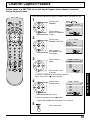
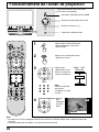
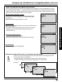
Searching for the desired channel (Channel search) .............................................................. 32
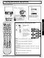
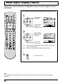
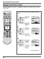
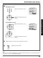
Playing peripheral equipment ................................................................................................... 33
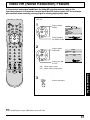
Mute / Freeze / SAP .................................................................................................................... 34
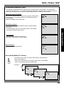
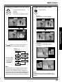
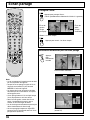
Split screen ................................................................................................................................. 36
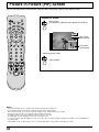
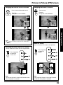
Picture in Picture (PIP) Screen .................................................................................................38
Getting Started
Basic Operation

6
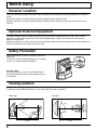
Receiver Location
Locate for comfortable viewing. Avoid placing where sunlight or other bright light (including reflections) will fall on the
screen.
Use of some types of fluorescent lighting can reduce remote control transmitter range.
Adequate ventilation is essential to prevent internal component failure. Keep away from areas of excessive heat or
moisture.
Optional External Equipment
The Video / Audio connection between components can be made with shielded video and audio cables. For best
performance, video cables should utilize 75 Ω coaxial shielded cables. Cables are available from your dealer or
electronic supply house.
Before you purchase any cables, be sure you know what type of output and input connectors your various components
require. Also determine the length of cable you’ll need.
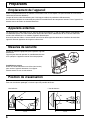
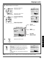
Safety Precaution
Please take safety precautions to prevent the unit from
falling over.
The unit may fall over during earthquakes, or if someone
stands on or shakes the projection display.
Fixing to a wall
Use a strong rope or a chain (not included) to fasten
the projection display firmly to a strong support such as
a wall or pillar.
Before Using
Viewing position
<Side view> <Top view>
To optimize your viewing comfort, please follow the viewing guidelines shown in the diagrams below.
If viewing for an extended period of time, sit as far back from the screen as possible.
30°
30°
1.5 m
70°
70°
1.5 m

7
Getting Started
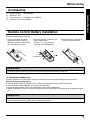
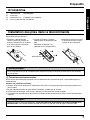
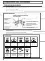
Accessories
Requires two AA batteries (supplied).
1.Turn the Transmitter face down.
Remove top cover by pressing
down on marking and sliding cover
off in the direction indicated.
2.Install the batteries as shown in the
battery compartment.
(Polarity + or – must match the
markings in the compartment).
3.Replace the cover and slide in
reverse until the lock snaps.
Precaution on battery use
Incorrect installation can cause battery leakage and corrosion that will damage the remote control transmitter.
Observe the following precautions:
Whenever you remove the batteries, you may need to reset the remote control infrared codes. We recommend
that you record the code on page 66, prior to setting up the remote.
Helpful Hint:
For frequent remote control users, replace old batteries with Alkaline batteries for longer life.
1. Batteries should always be replaced as a pair. Always use new batteries when replacing the old set.
2. Do not mix battery types (example: “Zinc Carbon” with “Alkaline”).
3. Do not attempt to charge, short-circuit, disassemble, heat or burn used batteries.
4. Battery replacement is necessary when the remote control acts sporadically or stops operating the projection display
set.
Two AA size
Remote Control Battery Installation
(1) Remote Control (EUR7603Z80)
(2) Batteries 2 “AA”
(3) RGB Cable (2 m) (LSJA0239-1 or LSJA0443)
(4) Accessory Air Filter (LSYC0239)
Before Using
Helpful Hint:

8
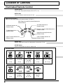
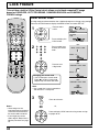
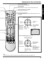
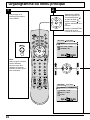
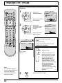
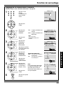
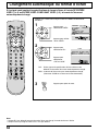
Number keys
When 6 is pressed, channel 6 is displayed in single screen. (P. 29)
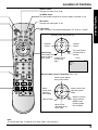
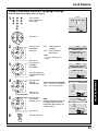
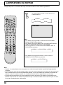
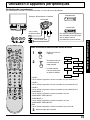
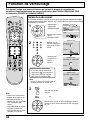
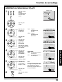
Location of Controls
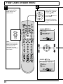
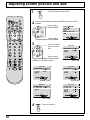
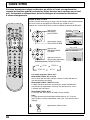
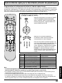
Illuminated Remote Control
POWER button
Press to turn the projection display ON or OFF. (P. 21)
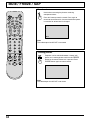
MUTE button
Press this button to mute the sound. (P. 34)
Mode Selection buttons
Selects the operation mode for the remote control. (PP. 65-71)
DVD (Digital Versatile Disc) Mode Selection for
Remote Control
VCR Mode Selection for
Remote Control
TV Mode Selection for
Remote Control
Digital TV Mode Selection for
Remote Control
Aux Mode Selection for
Remote Control
Receiver / Amplifier Mode Selection for
Remote Control
Cable TV Mode Selection for
Remote Control
Digital Broadcasting Satellite for
Remote Control
R-TUNE button
Press to view previous channel or video mode.
BBE sound
ON/OFF
CH Search
FREEZESPLIT Function/
PIP SIZE
PIP ON/OFFPIP Move PIP/SPLIT SWAP
(P. 39) (P. 38) (PP. 36, 39) (P. 34) (PP. 37, 39)
(P. 32) (P. 43)
Function buttons
PIP/SPLIT
CH Up
(PP. 37, 39)
PIP/SPLIT
CH Down
(PP. 37, 39)

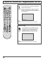
9
Getting Started
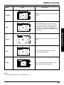
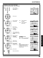
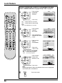
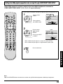
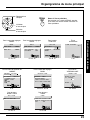
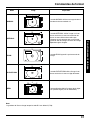
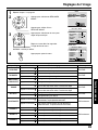
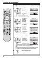
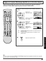
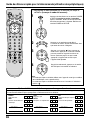
ASPECT button
Changes the screen size. (P. 30)
Light button
Lights all buttons. The selected mode button (TV, VCR, etc.) flashes.
TV/VIDEO button
This input mode changes each time this button is pressed. (P. 33)
Reduces
volume
Changes to the next channel up
Increase
volume
The screen below
is displayed for 5
seconds.
Changes to the
next channel
down
Returns to normal
viewing from the
MENU screen.
Previous before
item in MENU.
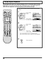
Location of Controls
SAP button
Changes the audio mode. (P. 35)
Display menu
Press the ACTION
button to display
Menu screen
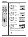
Note:
This section describes TV mode only. For other modes, see pages 65-71.
21HC
CBA
LAMRON
OERETS
PAS
ONOM
When the Menu screen is displayed, (PP. 22, 23)
Moves
cursor to the
left during
menu mode.
Moves cursor upward
during menu mode.
Moves cursor
downward during
menu mode.
Moves cursor to the
right during menu
mode.
Sets the items.
(P. 29)

10
A
A
Open
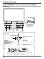
Controls and Terminals on the projection display
< FRONT >
LAMP indicator
This indicator lights up when there
is a malfunction with the lamp unit.
(PP. 21, 64, 72)
TEMP indicator
This indicator lights up when
there is an abnormal
temperature in the unit.
(P. 72)
Remote Control Sensor
POWER button/
POWER indicator
(P. 21)
Lamp unit
(P. 64)
Speaker cover
Press the mark on
the center of the front
cover to open.
Volume up(+) / down(–) buttons
(P. 28)
Channel up / down buttons
(P. 29)
PC Input terminal
(P. 18)
Input 3 terminals
(P. 15)
Location of Controls
Phones jack
Connect an earphone/headphones
(not supplied) to the Phones jack.
Speaker cover
Air filter
(P. 62)

11
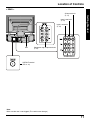
Getting Started
< REAR >
Component signal input terminals
(P. 16)
AV out terminals
(P. 17)
Input 1 terminals
(P. 15)
Input 2 terminals
(P. 15)
Location of Controls
VHF/UHF terminal
(PP. 12-14)
Vent
Note:
Make sure the vent is not clogged. (This could cause damage.)

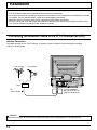
12
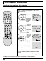
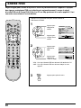
Connecting the Antenna / Cable to the RF in Terminal (No VCR)
Antenna Connection
For proper reception of VHF / UHF channels, an external antenna is required. For best reception an outdoor
antenna is recommended.
UHF AntennaVHF Antenna
Mixer
RF
Coaxial Cable
VHF/UHF TERMINAL
ON THE BACK OF THE
PROJECTION DISPLAY
Installation
When using “Nut type” RF coaxial cables, tighten with fingers only. Overtightening may damage terminals.
WARNING
• Turn off the power supply for all components before making any connections.
• If the cables necessary for connecting a component to the system are not included with the component or available
as an option, you may need to fashion a cable to suit the component concerned.
• Read the instruction manual for each system component carefully before connecting it.
• If there is a lot of jitter in the video signal input from the video source, the picture on the screen may flicker. In this
case, it will be necessary to connect a TBC (time base corrector).
Notes on connections

13
Getting Started
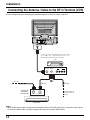
Cable Connection
Use this configuration when connecting the projection display to a cable TV system.
Notes:
• Certain cable systems offset some channels to reduce interference or have Premium (scrambled) channels. A cable
converter box is required for proper reception. Check with your local Cable company for its compatibility require-
ments.
• For reception of cable channels (01 - 125) connect the cable supplied by your local cable company.
Antenna Mode must be set to CABLE. (P. 24)
Installation
CABLE BOX
INPUT OUTPUT
TERMINAL ON
THE BACK OF
THE CABLE BOX
In from cable
Connect the cable from the antenna
or cable system to the VHF/UHF
terminal on the back of the
Projection display..
In from cable
Or

14
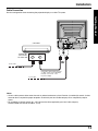
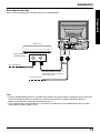
Use this configuration when connecting the projection display to a cable TV system using VCR.
Notes:
• When the RF coaxial cable is connected to the projection display VHF/UHF terminal via a cable box or VCR, set the
TV channel to CH3 or CH4. This does not apply when signal is input from VIDEO INPUT.
Installation
Connecting the Antenna / Cable to the RF in Terminal (VCR)
Connect the cable from the Output terminal on the back
of the Cable Box or antenna/cable system to the
Antenna input terminal on the back of the VCR.
CABLE BOX
TO VCR
OUTPUT
S-VIDEO
VIDEO
L-AUDIO-R
TO VCR
INPUT OUTPUT
OUTPUT INPUT
VCR
TERMINAL ON
THE BACK OF
THE CABLE BOX
In from cable
Incoming Cable from
Antenna or Cable TV
System
Or

15
Getting Started
Installation
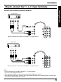
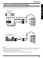
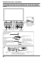
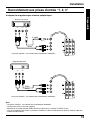
How to connect the “1, 2, 3” Input Terminals
Connects VCRs and other peripheral equipment
Similar connections are available at the INPUT 1, 2, 3 input terminals.
Notes:
• Similar connections are available at the INPUT 1, 2, 3 input terminals.
• Input 3 is located on the front of the unit.
• Select the desired VIDEO input position by pressing the TV/VIDEO button. (P. 33)
• When connecting video cables, priority is given to the S-Video cable when the S-Video input terminal and the video
input terminal are connected at the same time.
(S-VHS VCR)
Audio
OUT
Video
OUT
S-Video
OUT
RL
S-VIDEO
AUDIO
(VHS VCR)
VIDEO
AUDIO
Audio
OUT
Video
OUT
R
L
Similar connections are available at the INPUT 1, 2, 3 input terminals.

16
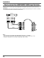
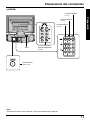
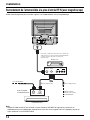
How to connect the COMPONENT VIDEO Input Terminals
Notes:
• Similar connections are available at the COMPONENT VIDEO INPUT 1, 2 Terminals.
• Select the desired COMPONENT VIDEO INPUT position by pressing the TV/VIDEO button. (P. 33)
• Component video signals that can be input are 480i, 480p, 720p, and 1080i.
Installation
Audio
OUT
P
B
YP
R
DVD(Y/P
B
/P
R
) OUT
LR
DVD Player
COMPONENT VIDEO
AUDIO
Because each Y, PB, and PR signal is input independently, the Component signal allows for more accurate color
reproduction.
The Component signal output terminal indication will differ according to the output device (Y, PB / Cb, PR / Cr). Please
read the operating instructions included with the output device.

17
Getting Started
Installation
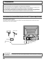
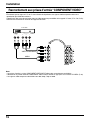
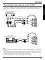
How to connect the AV Out Terminals
The “AV Out” Terminals output the same signals as the main picture on the projection display screen and sound from
the speaker at that time, e.g. TV programs or signals from INPUT 1, 2, 3 terminals.
Notes:
• Never connect the VIDEO IN and OUT terminals to the same video recorder, as this could cause incorrect operation.
• Even if TV is in Split or PIP mode, OUT terminals only output the main picture and sound signals. A sub-picture,
including channel search, etc., will not be output.
• VIDEO OUT terminals will not output Y, PB, PR, or RGB signals.
• The S-Video OUT terminal outputs the same signal that is input from the S-Video IN terminal.
Recording Equipment
(VHS VCR)
VIDEO
AUDIO
Audio
IN
Video
IN
S-Video
IN
S-VIDEO
R
L
(A Stereo Amplifier and Speakers)
Stereo System
AUDIO
Or

18
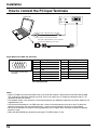
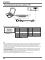
How to connect the PC Input Terminals
Signal Names for D-SUB 15P Connector
Pin Layout for PC Input
Terminal
Notes:
• Some PC models cannot be connected to the set. A conversion adapter is required to use the RGB cable (D-SUB
15P) to connect a Macintosh computer to the set. There is no need to use an adapter for computers with PC / AT
compatible D-SUB 15P terminal.
• The computer shown in the illustration is for example purposes only. Additional equipment and cables shown are not
supplied with this set.
• The picture will become dark if an RGB signal with a vertical scanning frequency of 62 Hz is input. To obtain the
optimum picture quality with the projection display, a vertical scanning frequency of 60 Hz is recommended.
• Do not set the horizontal and vertical scanning frequencies for PC signals which are above or below the specified
frequency range.
• Select the desired RGB input position by pressing the TV/VIDEO button. (P. 33)
Installation
PC audio cable (M3 stereo mini pin)
Connect a cable which matches
the audio output terminal on the computer.
Conversion adapter (If necessary)
RGB cable (D-SUB 15P)
COMPUTER
Pin No. Signal name
1R
2G
3B
4NC
5NC
6 Ground for R
7 Ground for G
8 Ground for B
Pin No. Signal name
9NC
10 Ground
11 NC
12 NC
13 HD/CSYNC
14 VD
15 NC
1
678
3
9
45
10
15 14 13 12 11
2
NC: Not connected

19
Getting Started
Installation
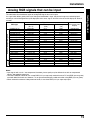
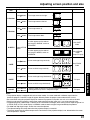
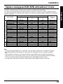
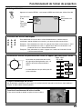
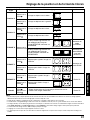
Analog RGB signals that can be input
The table below lists the different types of analog RGB signals that can be input.
If a signal which differs greatly from any of the types listed below is input, the picture image may not be displayed
correctly, or a black background may be displayed. At this time, “signal” will flash in the on-screen display for about 5
seconds.
Notes:
• Input signals with a mark * are compressed, therefore, picture quality may be different than with not compressed
signals, due to digital processing.
• The front D-SUB15P connector can accept RGB (H-V sync separate) used with most of PC and RGB (sync on green)
used with older Macintosh etc. However, it is not guaranteed to display stable color when using RGB (sync on green).
• When used with an external video processor/scaler, it must have RGB (H-V sync separate) output.
Personal Computer Signals
DTV Format
Signals
Mode type
Signal data
No. of dots
(H x V)
Horizontal frequency
(kHz)
Vertical frequency
(Hz)
VGA400 (70 Hz) 640 X 400 31.47 70.08 VGA400 70Hz
VGA480 (60 Hz) 640 X 480 31.47 59.94 VGA 60Hz
Macintosh 13˝ 640 X 480 35.00 66.67 MAC 13
VESA400 (85 Hz) 640 X 400 37.86 85.08 VESA 85Hz
VESA480 (72 Hz) 640 X 480 37.86 72.81 VGA 72Hz
VESA480 (75 Hz) 640 X 480 37.50 75.00 VGA 75Hz
VESA480 (85 Hz) 640 X 480 43.27 85.01 VGA 85Hz
SVGA (56 Hz) 800 X 600 35.16 56.25 SVGA 56Hz
SVGA (60 Hz) 800 X 600 37.88 60.32 SVGA 60Hz
SVGA (72 Hz) 800 X 600 48.08 72.19 SVGA 72Hz
SVGA (75 Hz) 800 X 600 46.88 75.00 SVGA 75Hz
SVGA (85 Hz) 800 X 600 53.67 85.06 SVGA 85Hz
Macintosh 16″ 832 X 624 49.73 74.55 MAC 16
* XGA (60 Hz) 1 024 X 768 48.36 60.00 XGA 60Hz
* XGA (70 Hz) 1 024 X 768 56.48 70.07 XGA 70Hz
* XGA (75 Hz) 1 024 X 768 60.02 75.03 XGA 75Hz
* Macintosh 19″ 1 024 X 768 60.24 74.93 MAC 19
* XGA (85 Hz) 1 024 X 768 68.68 85.00 XGA 85Hz
480 i 664 X 485 15.73 29.97 480 i
480 p 720 X 483 31.47 59.94 480 p
720 p 1 280 X 720 45.00 60.00 720 p
*1080 i 1 920 X 1 080 33.75 30.00 1080 i
Information menu
display

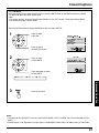
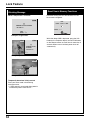
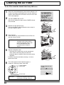
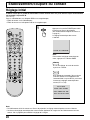
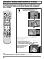
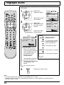
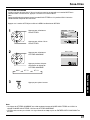
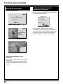
20
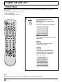
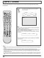
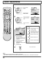
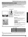
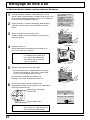
Press the POWER button to turn the
projection display on.
(Refer to page 21 for “Turning the Power
ON and OFF”.)
1
GNIDEECORP TES OTUA HC
Automatic Channel Setting is performed.
Power ON and OFF
First, check the connection of the Plug to the Wall Outlet and the Antenna/Cable to the RF in Terminal.
(PP. 12-14.)
If using Cable Box, DSS Receiver, or VCR,
• Turn on Cable Box.
• Turn off DSS Receiver, or VCR.
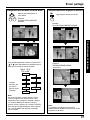
Case 1
Case 2
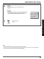
When setup is complete, the lowest
channel picture appears.
If setup is incomplete, the following
screen appears. Check connection of
Antenna/Cable to the RF in Terminal,
then try Automatic Channel Setting
again. (PP. 24, 25)
Note:
When the unit is turned on for the first time, Automatic Channel Setting is performed.
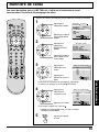
Initial Setup
Note:
To cancel AUTO SET in progress, press the
SWAP button.
NIAGA YEK NOITCA SSERP
ANNETNA KCEHC ESAELP
NEHT NOITCENNOC ELBAC
DNUOF HC ON
La page charge ...
La page charge ...
La page charge ...
La page charge ...
La page charge ...
La page charge ...
La page charge ...
La page charge ...
La page charge ...
La page charge ...
La page charge ...
La page charge ...
La page charge ...
La page charge ...
La page charge ...
La page charge ...
La page charge ...
La page charge ...
La page charge ...
La page charge ...
La page charge ...
La page charge ...
La page charge ...
La page charge ...
La page charge ...
La page charge ...
La page charge ...
La page charge ...
La page charge ...
La page charge ...
La page charge ...
La page charge ...
La page charge ...
La page charge ...
La page charge ...
La page charge ...
La page charge ...
La page charge ...
La page charge ...
La page charge ...
La page charge ...
La page charge ...
La page charge ...
La page charge ...
La page charge ...
La page charge ...
La page charge ...
La page charge ...
La page charge ...
La page charge ...
La page charge ...
La page charge ...
La page charge ...
La page charge ...
La page charge ...
La page charge ...
La page charge ...
La page charge ...
La page charge ...
La page charge ...
La page charge ...
La page charge ...
La page charge ...
La page charge ...
La page charge ...
La page charge ...
La page charge ...
La page charge ...
La page charge ...
La page charge ...
La page charge ...
La page charge ...
La page charge ...
La page charge ...
La page charge ...
La page charge ...
La page charge ...
La page charge ...
La page charge ...
La page charge ...
La page charge ...
La page charge ...
La page charge ...
La page charge ...
La page charge ...
La page charge ...
La page charge ...
La page charge ...
La page charge ...
La page charge ...
La page charge ...
La page charge ...
La page charge ...
La page charge ...
La page charge ...
La page charge ...
La page charge ...
La page charge ...
La page charge ...
La page charge ...
La page charge ...
La page charge ...
La page charge ...
La page charge ...
La page charge ...
La page charge ...
La page charge ...
La page charge ...
La page charge ...
La page charge ...
La page charge ...
La page charge ...
La page charge ...
La page charge ...
La page charge ...
La page charge ...
La page charge ...
La page charge ...
La page charge ...
La page charge ...
La page charge ...
La page charge ...
La page charge ...
La page charge ...
La page charge ...
La page charge ...
La page charge ...
La page charge ...
La page charge ...
La page charge ...
La page charge ...
La page charge ...
-
 1
1
-
 2
2
-
 3
3
-
 4
4
-
 5
5
-
 6
6
-
 7
7
-
 8
8
-
 9
9
-
 10
10
-
 11
11
-
 12
12
-
 13
13
-
 14
14
-
 15
15
-
 16
16
-
 17
17
-
 18
18
-
 19
19
-
 20
20
-
 21
21
-
 22
22
-
 23
23
-
 24
24
-
 25
25
-
 26
26
-
 27
27
-
 28
28
-
 29
29
-
 30
30
-
 31
31
-
 32
32
-
 33
33
-
 34
34
-
 35
35
-
 36
36
-
 37
37
-
 38
38
-
 39
39
-
 40
40
-
 41
41
-
 42
42
-
 43
43
-
 44
44
-
 45
45
-
 46
46
-
 47
47
-
 48
48
-
 49
49
-
 50
50
-
 51
51
-
 52
52
-
 53
53
-
 54
54
-
 55
55
-
 56
56
-
 57
57
-
 58
58
-
 59
59
-
 60
60
-
 61
61
-
 62
62
-
 63
63
-
 64
64
-
 65
65
-
 66
66
-
 67
67
-
 68
68
-
 69
69
-
 70
70
-
 71
71
-
 72
72
-
 73
73
-
 74
74
-
 75
75
-
 76
76
-
 77
77
-
 78
78
-
 79
79
-
 80
80
-
 81
81
-
 82
82
-
 83
83
-
 84
84
-
 85
85
-
 86
86
-
 87
87
-
 88
88
-
 89
89
-
 90
90
-
 91
91
-
 92
92
-
 93
93
-
 94
94
-
 95
95
-
 96
96
-
 97
97
-
 98
98
-
 99
99
-
 100
100
-
 101
101
-
 102
102
-
 103
103
-
 104
104
-
 105
105
-
 106
106
-
 107
107
-
 108
108
-
 109
109
-
 110
110
-
 111
111
-
 112
112
-
 113
113
-
 114
114
-
 115
115
-
 116
116
-
 117
117
-
 118
118
-
 119
119
-
 120
120
-
 121
121
-
 122
122
-
 123
123
-
 124
124
-
 125
125
-
 126
126
-
 127
127
-
 128
128
-
 129
129
-
 130
130
-
 131
131
-
 132
132
-
 133
133
-
 134
134
-
 135
135
-
 136
136
-
 137
137
-
 138
138
-
 139
139
-
 140
140
-
 141
141
-
 142
142
-
 143
143
-
 144
144
-
 145
145
-
 146
146
-
 147
147
-
 148
148
-
 149
149
-
 150
150
-
 151
151
-
 152
152


Panasonic PT40LC12K Mode d'emploi
- Catégorie
- Téléviseurs LCD
- Taper
- Mode d'emploi
- Ce manuel convient également à
dans d''autres langues
Documents connexes
Autres documents
-
Sony KP-EF61 Manuel utilisateur
-
Toshiba Projection Television 44HM85 Manuel utilisateur
-
-
-
Polaroid LCD-1550 Mode d'emploi
-
-
Quasar EUR511166 Manuel utilisateur
-
 ADS Technologies TV ELITE XGA Manuel utilisateur
-
SwissVoice CH05 ePure Mobile Corded Handset Manuel utilisateur
