Tripp Lite 230V 2U Rackmount UPS Systems Le manuel du propriétaire
- Catégorie
- Alimentations sans interruption (UPS)
- Taper
- Le manuel du propriétaire

1
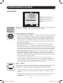
Owner’s Manual
Warranty
Registration
Register online today for a
chance to win a FREE Tripp Lite
product! www.tripplite.com/warranty
1111 W. 35th Street, Chicago, IL 60609 USA • www.tripplite.com/support
Copyright © 2013 Tripp Lite. All rights reserved. SmartPro
®
is a registered trademark of Tripp Lite.
Important Safety Instructions 2
Mounting 4
Quick Installation 6
Optional Installation 7
Basic Operation 9
Storage and Service 17
Battery Replacement 18
Warranty Registration 24
Español 25
Français 49
Русский 73
SmartPro
®
2U Rackmount
Intelligent, Line-Interactive UPS Systems
230V Sine Wave Output • 1000VA—3000VA Capacities
Extended Runtime Options
SMX1000RT2U
(Series Number: AG-0072)
SMX1500XLRT2U
(Series Number: AG-0071)
SMX2200XLRT2U
(Series Number: AG-0070)
SMX3000XLRT2UA
(Series Number: AG-0069)
Not suitable for mobile applications.
13-09-242-93-3184.indb 1 12/9/2013 10:13:37 AM

2
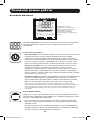
Important Safety Instructions
SAVE THESE INSTRUCTIONS
This manual contains important instructions that should be followed during the installation,
operation and storage of this product. Failure to heed these warnings may affect the warranty.
UPS Location Warnings
• UsecautionwhenliftingtheUPS.BecauseoftheconsiderableweightofallrackmountUPS
systems, at least two people should assist in lifting and installing them.
• InstalltheUPSindoors,awayfromexcessmoistureorheat,dustordirectsunlight.
• Forbestperformance,theambienttemperatureneartheUPSshouldbebetween0°Cand40°C
(between32°Fand104°F).
• LeaveadequatespacearoundallsidesoftheUPSforproperventilation.Donotobstructitsvents
or fan openings.
• WhenmountingtheUPSsysteminatowerorientation,makesuretheLCDScreenpanelisatthe
topoftheUPS,notatthebottom.
• Donotmountunitwithitsfrontorrearpanelfacingdown(atanyangle).Mountinginthismanner
will seriously inhibit the unit’s internal cooling, eventually causing product damage not covered
under warranty.
UPS Connection Warnings
• TheUPScontainsitsownenergysource(battery).Theoutputterminalsmaybeliveevenwhen
theUPSisnotconnectedtoanACsupply.
• ConnecttheUPStoaproperlygroundedACpoweroutlet.DonotmodifytheUPS’spluginaway
thatwouldeliminatetheUPS’sconnectiontoground.Donotuseadaptersthateliminatethe
UPS’sconnectiontoground.
• ThepoweroutletthatsuppliestheUPSshouldbeinstalledneartheUPSandbeeasily
accessible.
• DonotplugtheUPSintoitself;thiswilldamagetheUPSandvoidyourwarranty.
• IfyouareconnectingtheUPStoamotor-poweredACgenerator,thegeneratormustprovide
filtered,frequency-regulatedcomputer-gradeoutput.ConnectingtheUPStoageneratorwillvoid
itsUltimateLifetimeInsurance.
Equipment Connection Warnings
• Useofthisequipmentinlifesupportapplicationswherefailureofthisequipmentcanreasonably
beexpectedtocausethefailureofthelifesupportequipmentortosignificantlyaffectitssafety
oreffectivenessisnotrecommended.Donotusethisequipmentinthepresenceofaflammable
anestheticmixturewithair,oxygenornitrousoxide.
• DonotconnectsurgesuppressorsorextensioncordstotheoutputoftheUPS.Thismight
damagetheUPSandmayaffectthesurgesuppressorandUPSwarranties.
13-09-242-93-3184.indb 2 12/9/2013 10:13:37 AM

3
Battery Warnings
• Batteriescanpresentariskofelectricalshockandburnfromhighshort-circuitcurrent.Observe
properprecautions.Donotdisposeofthebatteriesinafire.DonotopentheUPSorbatteries.
Donotshortorbridgethebatteryterminalswithanyobject.UnplugandturnofftheUPSbefore
performingbatteryreplacement.Usetoolswithinsulatedhandles.Therearenouser-serviceable
partsinsidetheUPS.Batteryreplacementshouldbeperformedonlybyauthorizedservice
personnel using the same number and type of batteries (Sealed Lead-Acid). The batteries
arerecyclable.Refertoyourlocalcodesfordisposalrequirementsorvisitwww.tripplite.com/
UPSbatteryrecyclingforrecyclinginformation.TrippLiteoffersacompletelineofUPSSystem
ReplacementBatteryCartridges(R.B.C.).VisitTrippLiteontheWebatwww.tripplite.com/support/
battery/index.cfmtolocatethespecificreplacementbatteryforyourUPS.TheRBCTypecan
alsobefoundonthelabelaffixedtotheBatteryRetentionPlate.
• Duringhot-swapbatteryreplacement,theUPSwillnotprovidebackuppowerintheeventofa
blackout or other power interruptions.
• DonotoperatetheUPSwithoutbatteries.
External Battery Connection Warnings
• Whenaddingexternalbatterypackstoselectmodelswithexternalbatterypackconnectors,
connectonlyTrippLite-recommendedbatterypacksofthecorrectvoltageandtype.Donot
connectordisconnectbatterypackswhentheUPSisoperatingonbatterypower.
Visitwww.tripplite.com/support/battery/index.cfmtolocatethesupportedbatterytype(s)for
yourUPS.
Important Safety Instructions
13-09-242-93-3184.indb 3 12/9/2013 10:13:37 AM

4
A
AB
C
CB
1
2
3
4
D
D
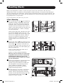
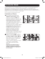
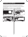
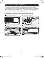
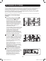
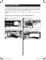
Mounting (Rack)
Mountyourequipmentineithera2-postor4-postrackorrackenclosure.Theusermust
determinethefitnessofhardwareandproceduresbeforemounting.Ifhardwareandprocedures
are not suitable for your application, contact the manufacturer of your rack or rack enclosure. The
procedures described in this manual are for common rack and rack enclosure types and may not
be appropriate for all applications.
Note: The illustrations may differ from your model.
4-Post Mounting
1
The included plastic pegs
A
will temporarily
support the empty rackmount shelves
B
while you install the permanent mounting
hardware.Insertapegnearthecenterof
the front and rear bracket of each shelf as
shown. (Each front bracket has 6 holes and
each rear bracket has 3 holes.) The pegs
will snap into place.
Afterinstallingthepegs,expandeachshelf
to match the depth of your rack rails. The
pegswillfitthroughthesquareholesinthe
rack rails to support the shelves. Refer to
the rack unit labels to confirm that the
shelves are level in all directions. Note: The
support ledge of each shelf must face
inward.
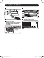
2
Secure the shelves
B
to the mounting rails
permanently using the included screws and
cup washers
C
as shown. Place the cup
washer between the screw and the rack so
that the screw enters the wider opening of
the cup washer first.
Place4screwstotalatthefrontand4
screws total at the back.
Tighten all screws before proceeding.
Warning: Do not attempt to install your
equipment until you have inserted and
tightened the required screws. The
plastic pegs will not support the weight
of your equipment.
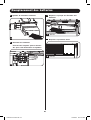
3
Attachyourequipment’smountingbrackets
to the forward mounting holes of the
cabinet using the hardware included with
yourequipment.Themountingbracket
“ears” should face forward. (Some
equipmentmayhavepre-installedor
integral mounting brackets.)
4
Withtheaidofanassistant(ifnecessary),
liftyourequipmentandslideitintothe
shelves.Attachtheequipmentmounting
brackets to the forward mounting rails with
user-supplied screws and washers
D
.
Tighten all screws securely.
13-09-242-93-3184.indb 4 12/9/2013 10:13:42 AM

5
Mounting (Rack) continued
2-Post Mounting
2-postmountingrequiresaTrippLite2-PostRackmountInstallationKit(model:2POSTRMKITWM,
sold separately).
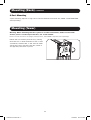
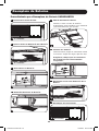
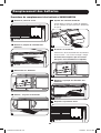
Mounting (Tower)
Warning: When mounting the UPS system in a tower orientation, make sure the LCD
Screen panel is at the top of the UPS, not at the bottom.
Note: To mount the UPS in an upright (tower) position, 2-9USTAND is required (sold separately).
RotatetheLCDScreenpanelforeasyviewing
whiletheUPSistowermounted.Insertasmall
screwdriver, or other tool, in the slots on either
side of the panel. Pop the panel out, rotate it
and pop the panel back in place.
13-09-242-93-3184.indb 5 12/9/2013 10:13:43 AM

6
2
3
A
1
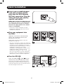
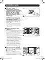
Quick Installation
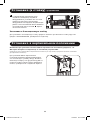
1
Insert a user-supplied power
cord (with country-specific
plug) into the UPS Systems
IEC inlet connection. Plug the
other end into your country-
specific wall outlet.*
NOTE! After you plug the UPS into a live
AC outlet, the UPS (in “Standby Mode”)
will automatically charge its batteries,
but will not supply power to its outlets
until it is turned ON.
* See the UPS systems nameplate for input
requirements. Additional input cords are also
available from Tripp Lite.
2
Plug your equipment into
the UPS.*
AdditionalC13-to-C14interconnection
cord(s) are included to connect your
equipmenttotheUPS.
NOTE: Additional interconnection cords are
available from Tripp Lite.
* Your UPS is designed to support only electronic
equipment. You will overload the UPS if the total
VA ratings for all the equipment you connect
exceeds the UPS’s Output Capacity. To find your
equipment’s VA ratings, look on their
nameplates. If the equipment is listed in amps,
multiply the number of amps by 230 to
determine VA. (Example: 1 amp × 230 = 230
VA). If you are unsure if you have overloaded
the UPS’s outlets, see LOAD icon description in
LCDInterface section underBasicOperation.
3
Turn the UPS ON.
Press and hold the button
A
for one
second. The alarm will beep once briefly.
Note: UPS system will function properly upon
initial startup, however, maximum runtime and a
successful self-test will only be accessible after it
has been charged for 24 hours.
13-09-242-93-3184.indb 6 12/9/2013 10:13:45 AM

7
1A
1B
2A
4-5
2B
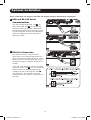
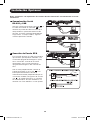
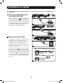
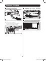
Optional Installation
These connections are optional. Your UPS will function properly without these connections.
1
USB and RS-232 Serial
Communications
UsetheincludedUSBcable(see
1A
) or
DB9serialcable(see
1B
) to connect the
communication port on your computer to
thecommunicationportofyourUPS.Install
on your computer the Tripp Lite PowerAlert
Software appropriate to your computer’s
operating system.
2
EPO Port Connection
This optional feature is only for those
applicationswhichrequireconnectiontoa
facility’sEmergencyPowerOff(EPO)circuit.
WhentheUPSisconnectedtothiscircuit,it
enablesemergencyshutdownoftheUPS’s
inverter.
Usingthecableprovided,connecttheEPO
portofyourUPS(see
2A
) to a user-supplied
normally closed or normally open switch
according to the circuit diagram (see
2B
).
TheEPOportisnotaphonelinesurge
suppressor;donotconnectaphonelineto
this port.
13-09-242-93-3184.indb 7 12/9/2013 10:13:48 AM

8
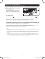
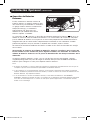
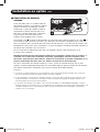
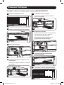
3
A
Optional Installation continued
3
External Battery Connection
(Select Models)
YourUPScomeswitharobustinternal
batterysystem;externalbatteriesare
neededonlytoextendruntime.Adding
externalbatterieswillincreaserecharge
time as well as runtime. Contact Tripp Lite
tofindoutwhichexternalbatterypacks
your model supports.
The illustration (see
3
)showsthelocationofyourUPS’sExternalBatteryConnector
A
where
you will insert the battery pack cable. Complete installation instructions for your battery pack
appearinthebatterypackowner’smanual.Makesurethatcablesarefullyinsertedintotheir
connectors.Smallsparksmayresultduringbatteryconnection;thisisnormal.
DonotconnectordisconnectbatterypackswhentheUPSisrunningonbatterypower.
Caution! When an external battery pack is connected, make sure the AC load does not
exceed the nameplate rating. Select models are derated when an external battery pack
is connected. See UPS nameplate label for derating details.
WhenconnectingexternalbatteriestotheUPS,gototheTrippLitewebsiteat
www.tripplite.com/en/support/bpconfig/index.cfmtodownloadtheExternalBatteryPackUtility
softwaretoconfigureyourUPSforexternalbatterysupport.
Note:
1. The runtime and charge rate will automatically recalculate once the External Battery Pack Tool process is
complete.
2. If the setup will no longer include external batteries, the UPS can be configured to work without external
batteries via the LCD Screen. See ExternalBatterySettingsControl section under BasicOperation for
details.
3. If external battery packs are removed, the UPS must be reset to “NO EXTERNAL BATTERY” via the LCD
interface or the External Battery Configuration Program available on the Tripp Lite website. Failure to do
so may result in damage to the internal batteries due to over-charging.
13-09-242-93-3184.indb 8 12/9/2013 10:13:50 AM

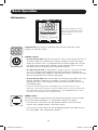
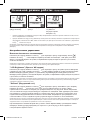
9
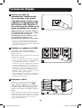
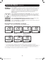
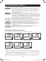
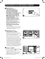
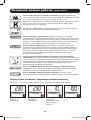
Note: This LCD image is shown
with all icons illuminated. Under
normal conditions, only select
icons will be lit.
Basic Operation
LCD Interface
3-Digit Display: This display is generally used to show values for a given
“Display”or“Control”screen.
“ON/OFF” Button
• To turn the UPS ON:AfteryouplugtheUPSintoaliveACoutlet,theUPS(in
”Standby” mode) will automatically charge its batteries, but will not supply
powertoitsoutletsuntilitisturnedON.WiththeUPSpluggedintoaliveAC
walloutlet,pressandholdthe“ON/OFF”buttonforonesecond.*TheUPS
willbeeponcetoindicateONstatus.Releasethebutton.
• To cold-start the UPS:Ifutilitypowerisabsent,youcan“cold-start”theUPS
(i.e.:turnitONandsupplypowerforalimitedtimefromitsbatteries)by
pressingandholdingthe“ON/OFF”buttonforonesecond.*TheUPSwillbeep
oncetoindicateONstatus.Releasethebutton.
• To turn the UPS OFF:WiththeUPSONandreceivingutilitypower,pressand
holdthe“ON/OFF”buttonfor2.5seconds.*TheUPSwillbeeponceto
indicateOFFstatus.ThenunplugtheUPSfromthewalloutlet.TheUPSwill
becompletelyOFF.
* If the user unintentionally presses the ON/OFF button, the OFF function can be
temporarily canceled by continuing to hold the ON/OFF button until the UPS beeps and
then momentarily pressing either the MODE button or the ENTER/MUTE button. Once
both buttons are released, the UPS will remain ON.
“MODE” Button
To enable viewing of power displays and control menu options, tap this button.
See“DisplayPowerConditions”&“ControlMenuOptions”fordetails.
• CanbeusedinconjunctionwiththeON/OFFbuttontocancelthe“OFF”
function.See“ON/OFFButton”instructionsabove.
• CanbeusedinconjunctionwiththeENTER/MUTEbuttontorestoretheLCD
toFactoryMode.See“ControlMenuOptions”.
13-09-242-93-3184.indb 9 12/9/2013 10:13:51 AM

10
Basic Operation continued
“ENTER/MUTE” Button
To toggle settings options while viewing a control menu option, tap this button.
TheUPSpowerfailurealarmcanalsobetemporarilysilencedbytappingthis
button.Oncesilenced,analarmwillautomaticallyre-soundtoindicatelow
battery conditions and can no longer be silenced.
•CanbeusedinconjunctionwiththeON/OFFbuttontocancelthe“OFF”
function.See“ON/OFFButton”instructionsabove.
•CanbeusedinconjunctionwiththeENTER/MUTEbuttontorestoretheLCD
toFactoryMode.See“ON/OFFButton”instructions.
Note: Alarm-free silent operation is available by setting the alarm to disable
(see CONTROL MENU OPTIONS / ALARM ENABLE-DISABLE section).
Battery Capacity:Thiswillbeactiveinall“Display”modes,butisnotshown
in “Control” modes.
AC Input:ThisindicatesthattheunitisrunninginLineModeandsupplyingAC
powertoequipmentconnectedtotheoutput.
Battery Input:ThiswillflashtoindicatethattheUPSisnotreceivingACinput
andisrunningininvertermode.TheBatteryInputiconisalsousedin
conjunctionwiththeEVENTSicontoindicateOnBatteryevents.
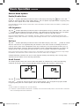
Replace Battery Icon: IntheeventthatUPSbatteriesexpireandrequire
replacement, this icon and the warning icon will flash. This icon will also flash
afterafailedUPSself-test(seetheBASICOPERATION/CONTROLMENU
OPTIONS/SELF-TESTsectionformoreinformation).
Warning: This will flash to let the user know that there’s a warning condition
and immediate action must be taken:
1.ForReplaceBattery:ReplaceBatteryandWarningiconsflashduringany
normal“Display”mode.
2.ForOverload:Load,WarningandLoadPercentageiconswillflash,thealarm
willsoundrepeatedlyandtheLCDscreenwillswitchfromtheuser-selected
displaymodetoLoadPercentage.OverloadindicationisavailableinbothAC
andbatterymodes.CAUTION!Anyoverloadconditionthatisnotcorrectedby
theuserimmediatelymaycausetheUPStoshutdownandceasesupplying
power in the event of a blackout or brownout.
EVENTS Icon:DisplayedinconjunctionwiththeAVRiconandBATTiconsto
indicatethenumberofOnBatteryorAVReventsthathaveoccurred.
Alarm Off:Indicatesthatthealarmisdisabled.
Alarm On: Indicatesthatthealarmisenabled.
13-09-242-93-3184.indb 10 12/9/2013 10:13:52 AM

11
Basic Operation continued
INPUT Icon: Indicatesthatthe3-digitvaluedisplayedistheInputVoltage.
OUTPUT Icon: Indicatesthatthe3-digitvaluedisplayedistheOutputVoltage.
LOAD Icon:Displayedintwomodes:
1.Displayedinconjunctionwiththe%iconand3-digitvaluetoindicatethe
load percentage.
2.DisplayedinconjunctionwithKWH/Dayand3-digitvaluetoindicatedaily
power consumption.
3.BoththeLOADiconandWarningiconwillflashtoindicateanoverload.
BATT Icon: Displayedintwomodes:
1.BATTicon(displayedinconjunctionwith%iconand3-digitvalue)indicates
theBatteryCapacity%.
2.BATTiconisshownwithTESTicontoindicateself-testmodeorcontrol
mode.
% Icon:Indicatesunitsof%.
TEST Icon:DisplayedinconjunctionwithBATTicontoindicatethattheUPSis
performing a self-test.
RUNTIME Icon:DisplayedinconjunctionwiththeMINiconand3-digitvalueto
indicate Runtime in minutes.
MIN Icon:Indicatesunitsofminutes.
1.DisplayedinconjunctionwithRUNTIMEiconand3-digitvaluetoindicate
battery runtime in minutes.
2.Displayedinconjunctionwiththe3-digitvalue(reporting“LCD”)toindicate
the minimum brightness.
VWA Icon: ThisisamultipurposeiconwhichindicatesunitsofVolts,VA,Watts,
orAmps(V,VA,W,orAwillbeshown).
K Icon: DisplayedinconjunctionwiththeWtoindicateKilowatts.Itisalso
usedinconjunctionwiththeWHand/DAYiconstoindicateKilowattHoursper
Day.
H and /DAY Icons:Displayedinconjunctionwith“K”and“W”iconstoindicate
KilowattHoursperday(KWH/DAY).
Sensitivity Icon: DisplayedtosettheACinputlinesensitivitysetting.
Sensitivitysettingsavailableare100%(Normal=FullCounterclockwisePOT),
50%(halfdelay),and25%(fulldelay=fullClockwisePOT).
SCROLL Icon:Whenenabled,thedisplaywillautomaticallycyclethrougheach
DISPLAYmodeoftheLCDoncepertwo-secondinterval.Ifabuttonispressed
whileScrollModeisenabled,thescrollfunctionwillpausefor10secondsto
allow the user to manually make menu selections before resuming scroll.
13-09-242-93-3184.indb 11 12/9/2013 10:13:52 AM

12
Automatic Voltage Regulation Icon:IndicatesthattheACinputiseitherlow
orhighandthattheAVRfunctionisactivelyboostingorcuttingtheline.The
AVRiconisalsousedinconjunctionwiththeEVENTSicontoindicateAVR
events.
EXTERNAL BATTERY Icon (Select Models):DisplayedonlywhentheEXTERNAL
BATTERYSETTINGCONTROLisactive.
BATTERY CAPACITY Icon:Usedtobetterdescribethebatterycapacitybar
graph.
Basic Operation continued
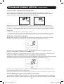
Display Power Conditions
Usethe button to advance through power conditions.
1.VoltageIn 2.VoltageOut 3. Estimated Runtime
(in minutes)
4.Load%
5.LoadWattage* 6.KWH/Day** 7.BatteryCapacity%
* Load Wattage is displayed in watts up to “999”, and then will be displayed in Kilowatts.
** The Kilowatt Hour usage per day reports daily power consumption of equipment connected to the UPS in
KWH in a 24-hour cycle. Press and hold the
button for 4 seconds to reset the accumulator to “0”.
Note: When the UPS is in Battery Mode (power is supplied to the output from the batteries), the BATTERY icon
will be lit in the display instead of the AC INPUT icon.
13-09-242-93-3184.indb 12 12/9/2013 10:13:53 AM

13
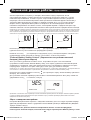
Basic Operation continued
Control Menu Options
Enable/Disable Alarm
Tap the buttonrepeatedlytoadvancetotheLCDdisplayfeaturingthe icon. Press the
buttontoselectONorOFFalarmmodesettings.Thelastoptiondisplayedbeforenavigatingaway
from this menu option will be the selected setting.
Note: Disabling the alarm via this control menu option will silence the alarm under all conditions, including low
battery conditions.
LCD Brightness
Tap the buttonrepeatedlytoadvancetotheLCDBrightnessdisplaymarked“LCD”.Pressthe
buttontoselectMediumBacklight(default),HighBacklightorDimBacklight.Thelastoption
displayed before navigating away from this menu option will be the selected setting.
Note: The default brightness is set at medium. Any time a button is pressed, the LCD will engage the high
brightness setting. After 2 minutes of inactivity, the backlight will revert to the selected setting until a button is
pressed.
Self-test
Tap the buttonrepeatedlytoadvancetotheTESTBATTdisplay.Pressthe button to initiate
thetest.Thetestwilllastapproximately10secondsastheUPSswitchestobatterytotestthe
capacitywithaload.Uponcompletionofthetest,thedisplaywillindicatePASorBAD(passor
bad)for20seconds,andthenreturntothehomescreen.Connectedequipmentcanremainon
duringthetest.DonotunplugyourUPStotestit;thiswillremovesafeelectricalgrounding.
Note: If the self-test result is BAD, it may be due to the batteries not being charged for 24 hours. Fully charge
the batteries and repeat the self-test. Please refer to the note under Step 3 on page 6.
AReplaceBatteryConditionwillresultintheReplaceBatteryandWarningiconsflashingevery
second and the audible alarm sounding repeatedly.
Scroll Control
This display option allows the user to select the option to automatically scroll each operating
conditionoftheUPS(suchasInputVoltage,OutputVoltageandRuntime)automatically.
Tap the button repeatedly to advance to the Scroll display as shown above.
Press the buttontoadvancetothenextavailableoption.Thelastoptiondisplayed,before
navigating away from this menu option, will be the selected setting.
Note:
1. Each condition is displayed in 2 second intervals.
2. If a button is pressed while Scroll Mode is enabled, the scroll function will pause for 10 seconds to allow the
user to manually make menu selections.
13-09-242-93-3184.indb 13 12/9/2013 10:13:54 AM

14
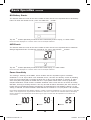
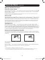
ON Battery Events
ThisfeatureallowstheusertoviewthenumberoftimestheUPShasexperiencedanONBattery
Event. To reset the counter to “0”, press and hold the button.
Basic Operation continued
Tap the buttonrepeatedlytoadvancetotheONBatteryEventsdisplay,asshownabove.
Note: The value displayed is a random value used for example reference.
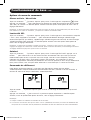
AVR Events
ThisfeatureallowstheusertoviewthenumberoftimestheUPShasexperiencedanAutomatic
VoltageRegulationEvent.Toresetthecounterto“0”,pressandholdthe button.
Tap the buttonrepeatedlytoadvancetotheAVRdisplay,asshownabove.
Note: The value displayed is a random value used for example reference.
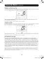
Power Sensitivity
Thissettingisnormallysetto100%,whichenablestheUPStoprotectagainstwaveform
distortionsinitsACinput.Whensuchdistortionoccurs,theUPSwillnormallyswitchtoproviding
puresinewavepowerfromitsbatteryreservesforaslongasthedistortionispresent.Insome
areaswithpoorutilitypowerorwheretheUPS’sinputpowercomesfromabackupgenerator,
frequentbrownoutsand/orchronicwaveformdistortioncouldcausetheUPStoswitchtobattery
toooften,drainingitsbatteryreserves.YoumaybeabletoreducehowoftenyourUPSswitchesto
batteryduetowaveformdistortionorbrownoutsbyexperimentingwithdifferentsettings.Asthe
settingisreduced,theUPSbecomesmoretolerantofvariationsinitsinputpower’sACwaveform.
Note: When experimenting with different settings, operate connected equipment in a safe test mode so that the
effect on the equipment of any waveform distortions in the UPS’s output can be evaluated without disrupting
critical operations. The experiment should last long enough to assure that all expected line conditions are
encountered.
13-09-242-93-3184.indb 14 12/9/2013 10:13:54 AM

15
YES
Basic Operation continued
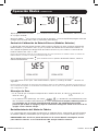
Tap the button repeatedly to advance to Sensitivity display, as shown on the previous page.
Press the button to advance through the options. The last option displayed, before navigating
away from this menu option, will be the selected setting.
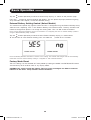
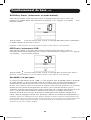
External Battery Setting Control (Select Models)
ThiscontrolmenuoptiononlyappearswhentheUPSisconfiguredusingtheExternalBatteryUtility
softwareandisreporting“YES”intheExternalBatteryLCDControlScreen.TheonlyavailableLCD
interfaceconfigurationoptionistochangethesettingfrom“YES”to“NO”externalbatteries.
Note: See the Optional Installation section for information on configuring the UPS for external battery operation
using the External Battery Utility software.
Tap the buttonrepeatedlytoadvancetotheExternalBatterydisplay,asshownbelow.
TosettheUPSto“NO”ExternalBattery,pressandholdthe buttonfor3.5seconds.
Note: The Battery Runtime calculation is based on this setting. The runtime and charger rate will automatically
recalculate once the external battery setting is configured for “NO” external batteries.
Factory Mode Reset
TheLCDsettingscanberestoredtoFactoryModebyholdingtheMODEandENTER/MUTEbuttons
simultaneouslyfor5secondswhileinanydisplaymode.
CAUTION: This action cannot be undone. The user must reconfigure the UPS for external
batteries if the UPS’s setup includes external batteries.
13-09-242-93-3184.indb 15 12/9/2013 10:13:55 AM

16
IEC 320-C13
IEC 320-C19
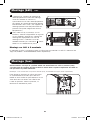
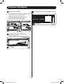
Basic Operation continued
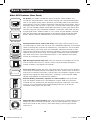
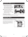
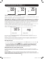
Other UPS Features (Rear Panel)
AC Outlets: AllmodelsincludeIEC320-C13outlets.Selectmodelsalso
includeIEC320-C19outlets.Theseoutletsprovideyourconnectedequipment
with AC line power during normal operation and battery power during blackouts
andbrownouts.TheUPSprotectsequipmentconnectedtotheseoutletsagainst
damagingsurgesandlinenoise.IfyouhaveaserialorUSBconnectiontoyour
UPS,youcanremotelyrebootconnectedequipmentbyturningtheoutletsOFF
andONusingTrippLite’sPowerAlertSoftware.Theoutletsaredividedintoone
ormoreloadbanks(labelled“LOAD1,”etc.)whichmayberemotelyswitched
OFFandONwithoutinterruptingpowertoequipmentconnectedtotheother
outlets.Outletslabelled“UNSWITCHED”maynotberemotelyswitchedoff.
Communications Ports (USB or RS-232): TheseportsconnectyourUPSto
anyworkstationorserver.UsewithTrippLite’sPowerAlertSoftwareandincluded
cables to enable your computer to automatically save open files and shut down
equipmentduringablackout.AlsousePowerAlertSoftwaretomonitorawide
varietyofAClinepowerandUPSoperatingconditions.ConsultyourPowerAlert
Software manual or contact Tripp Lite Customer Support for more information.
See“USBandRS-232SerialCommunications”inthe“OptionalInstallation”
section for installation instructions.
EPO (Emergency Power Off) Port: YourUPSfeaturesaEPOportthatmaybe
usedtoconnecttheUPStoacontactclosureswitchtoenableemergency
invertershutdown.SeeOptionalInstallation.
Accessory Slot: Remove the small cover panel from this slot to install optional
accessoriestoremotelymonitorandcontrolyourUPS.Refertoyouraccessory’s
manual for installation instructions. Contact Tripp Lite Customer Support at www.
tripplite.com/supportformoreinformation,includingalistofavailableSNMP,
network management and connectivity products.
External Battery Connector (optional on select models): Usetoconnect
TrippLiteexternalbatterypacksforadditionalruntime.Refertoinstructions
available with the battery pack for complete connection information and safety
warnings.Visitwww.tripplite.com/support/battery/index.cfmtolocatethe
supportedbatterytype(s)foryourUPS.
Output Breaker (select models): YourUPSfeaturesoneormorebreakersthat
protectyourUPSfromoutputoverload.Ifoneormorebreakerstrip,remove
some of the load on the circuit(s), then reset them by pressing the breaker
switch(es) in.
13-09-242-93-3184.indb 16 12/9/2013 10:13:56 AM

17
Basic Operation continued
Ground Screw: Usethistoconnectanyequipmentthatrequiresachassis
ground.
Storage and Service
Storage
BeforestoringyourUPS,turnitcompletelyOFF:withtheUPSONandreceivingutilitypower,press
andholdthe“ON/OFF”buttonfortwoseconds(analarmwillbeeponcebrieflyaftertheinterval
haspassed);then,unplugtheUPSfromthewalloutlet.IfyoustoreyourUPSforanextended
periodoftime,rechargetheUPSbatteriesonceeverythreemonths:plugtheUPSintoawall
outlet;allowittochargefor12hours;andthenunplugitandplaceitbackinstorage.Ifyouleave
yourUPSbatteriesdischargedforanextendedperiodoftime,theywillsufferapermanentlossof
capacity.
Service
AvarietyofExtendedWarrantyandOn-SiteServiceProgramsarealsoavailablefromTrippLite.For
moreinformationonservice,visitwww.tripplite.com/support.Beforereturningyourproductfor
service, follow these steps:
1. Review the installation and operation procedures in this manual to insure that the service
problem does not originate from a misreading of the instructions.
2. Iftheproblemcontinues,donotcontactorreturntheproducttothedealer.Instead,visitwww.
tripplite.com/support.
3. Iftheproblemrequiresservice,visitwww.tripplite.com/supportandclicktheProductReturns
link.FromhereyoucanrequestaReturnedMaterialAuthorization(RMA)number,whichis
requiredforservice.Thissimpleon-lineformwillaskforyourunit’smodelandserialnumbers,
alongwithothergeneralpurchaserinformation.TheRMAnumber,alongwithshipping
instructionswillbeemailedtoyou.Anydamages(direct,indirect,specialorconsequential)to
theproductincurredduringshipmenttoTrippLiteoranauthorizedTrippLiteservicecenteris
notcoveredunderwarranty.ProductsshippedtoTrippLiteoranauthorizedTrippLiteservice
centermusthavetransportationchargesprepaid.MarktheRMAnumberontheoutsideofthe
package.Iftheproductiswithinitswarrantyperiod,encloseacopyofyoursalesreceipt.
Return the product for service using an insured carrier to the address given to you when you
requesttheRMA.
13-09-242-93-3184.indb 17 12/9/2013 10:13:56 AM

18
1
3
2
4 x screws
4 x screws
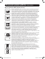
4
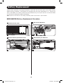
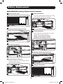
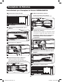
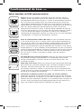
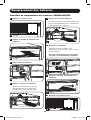
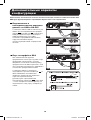
Battery Replacement
Undernormalconditions,theoriginalbatteriesinyourUPSwilllastmanyyears.SeeSafetysection
before replacing batteries. The batteries are designed for hot-swap replacement (i.e., leaving the
UPSinONmode),butsomequalifiedservicepersonnelmaywishtoputtheUPSintheOFFmode
anddisconnectequipmentbeforeproceeding.
Note: Refer to the label on the battery retention plate for the R.B.C. part number.
SMX1000RT2U Battery Replacement Procedure
2
Remove Battery Retention Plate
3
Disconnect Batteries
4
Remove/Recycle Batteries
1
Remove Front Panel
13-09-242-93-3184.indb 18 12/9/2013 10:14:00 AM

19
7
8
4 x screws
4 x screws
5
6
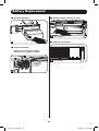
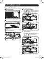
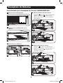
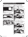
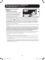
Battery Replacement
5
Add New Batteries
6
Connect Batteries
Always ensure that the battery
terminals are properly secured.
7
Replace Battery Retention Plate
8
Replace Front Panel
13-09-242-93-3184.indb 19 12/9/2013 10:14:03 AM

20
1
3
7
2
8
4 x screws
6 x screws
6 x screws
4 x screws
4
6
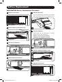
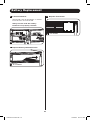
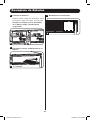
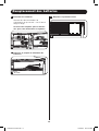
Battery Replacement
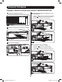
SMX1500RT2U Battery Replacement Procedure
2
Remove Battery Retention Plate
3
Disconnect Batteries
4
Remove/Recycle Batteries
6
Connect Batteries
Attach both sets of connectors as shown:
black-to-black and red-to-red.
Always ensure that the battery
terminals are properly secured.
7
Replace Battery Retention Plate
8
Replace Front Panel
1
Remove Front Panel
5
5
Add New Batteries
First, install the row of batteries by inserting
them, pressing forward and snapping them in.
13-09-242-93-3184.indb 20 12/9/2013 10:14:09 AM
La page charge ...
La page charge ...
La page charge ...
La page charge ...
La page charge ...
La page charge ...
La page charge ...
La page charge ...
La page charge ...
La page charge ...
La page charge ...
La page charge ...
La page charge ...
La page charge ...
La page charge ...
La page charge ...
La page charge ...
La page charge ...
La page charge ...
La page charge ...
La page charge ...
La page charge ...
La page charge ...
La page charge ...
La page charge ...
La page charge ...
La page charge ...
La page charge ...
La page charge ...
La page charge ...
La page charge ...
La page charge ...
La page charge ...
La page charge ...
La page charge ...
La page charge ...
La page charge ...
La page charge ...
La page charge ...
La page charge ...
La page charge ...
La page charge ...
La page charge ...
La page charge ...
La page charge ...
La page charge ...
La page charge ...
La page charge ...
La page charge ...
La page charge ...
La page charge ...
La page charge ...
La page charge ...
La page charge ...
La page charge ...
La page charge ...
La page charge ...
La page charge ...
La page charge ...
La page charge ...
La page charge ...
La page charge ...
La page charge ...
La page charge ...
La page charge ...
La page charge ...
La page charge ...
La page charge ...
La page charge ...
La page charge ...
La page charge ...
La page charge ...
La page charge ...
La page charge ...
La page charge ...
La page charge ...
-
 1
1
-
 2
2
-
 3
3
-
 4
4
-
 5
5
-
 6
6
-
 7
7
-
 8
8
-
 9
9
-
 10
10
-
 11
11
-
 12
12
-
 13
13
-
 14
14
-
 15
15
-
 16
16
-
 17
17
-
 18
18
-
 19
19
-
 20
20
-
 21
21
-
 22
22
-
 23
23
-
 24
24
-
 25
25
-
 26
26
-
 27
27
-
 28
28
-
 29
29
-
 30
30
-
 31
31
-
 32
32
-
 33
33
-
 34
34
-
 35
35
-
 36
36
-
 37
37
-
 38
38
-
 39
39
-
 40
40
-
 41
41
-
 42
42
-
 43
43
-
 44
44
-
 45
45
-
 46
46
-
 47
47
-
 48
48
-
 49
49
-
 50
50
-
 51
51
-
 52
52
-
 53
53
-
 54
54
-
 55
55
-
 56
56
-
 57
57
-
 58
58
-
 59
59
-
 60
60
-
 61
61
-
 62
62
-
 63
63
-
 64
64
-
 65
65
-
 66
66
-
 67
67
-
 68
68
-
 69
69
-
 70
70
-
 71
71
-
 72
72
-
 73
73
-
 74
74
-
 75
75
-
 76
76
-
 77
77
-
 78
78
-
 79
79
-
 80
80
-
 81
81
-
 82
82
-
 83
83
-
 84
84
-
 85
85
-
 86
86
-
 87
87
-
 88
88
-
 89
89
-
 90
90
-
 91
91
-
 92
92
-
 93
93
-
 94
94
-
 95
95
-
 96
96


Tripp Lite 230V 2U Rackmount UPS Systems Le manuel du propriétaire
- Catégorie
- Alimentations sans interruption (UPS)
- Taper
- Le manuel du propriétaire
dans d''autres langues
Documents connexes
-
Tripp Lite 230V 2U Rackmount UPS Systems Le manuel du propriétaire
-
-
-
-
-
-
-
-
Tripp Lite SMART1500RM2UL & SMART2200RM2UL Le manuel du propriétaire
-