wtw Cond 3400i Mode d'emploi
- Catégorie
- Mesure, test
- Taper
- Mode d'emploi
Ce manuel convient également à

Multi 340i
ba52319edfs04 06/2004
ba52319edfs
Operating manual
Bedienungsanleitung
Mode d’emploi
Instrucciones de operación
Universal Pocket Meter Page 3
Universal-Taschenmeßgerät Seite 17
Instrument de poche universel Page 31
Instrumento manual de medición universal Página 45
AR
R
C
L
S
T
O
C
A
L
M
O
6
7
1
9
2
7
O
°
C
m
g/l
ARng
TP

Multi 340i
2
Note to this
operating manual
This operating manual contains a description of
l all basic functions,
l all instructions for a safe operation, and
l all technical data in a compact form.
A more detailed description with notes for special applications is available as
a pdf document via internet under http://www.WTW.com.
Hinweise zu dieser
Bedienungs-
anleitung
Diese Bedienungsanleitung enthält in kompakter Form
l die Beschreibung aller Grundfunktionen,
l alle Hinweise für den sicheren Betrieb und
l alle technischen Daten.
Eine ausführlichere Beschreibung mit Hinweisen für besondere Anwendun-
gen ist als pdf-Dokument im Internet unter http://www.WTW.com erhältlich.
Remarque à ce
mode d’emploi
Ce mode d'emploi contient sous forme compacte
l la description de toutes les fonctions de base et
l toutes les informations assurant un fonctionnement sûr, ainsi que
l tous les données techniques.
Une description plus étendue contenant les informations sur des emplois
spéciaux peut être obtenue sous forme pdf dans l'internet sous http://
www.WTW.com.
Observatión
a estas
instrucciones
Este manual de instrucciones incluye la descripción en forma resumida de
l todas las funciones básicas,
l todas las observaciones que le garantizan el
l funcionamiento normal y seguro, asimismo todo las especificaciones y
datos técnicos.
En el internet, bajo http://www.WTW.com encuentra Ud. una descripción
más detallada, en formato pdf, para aplicaciones especiales.
Copyright
© Weilheim 2004, WTW GmbH

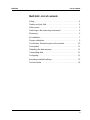
Multi 340i List of contents
3
Multi 340i - List of contents
Safety . . . . . . . . . . . . . . . . . . . . . . . . . . . . . . . . . . . . . . . . . . . . 4
Display and jack field . . . . . . . . . . . . . . . . . . . . . . . . . . . . . . . . 4
Mains power. . . . . . . . . . . . . . . . . . . . . . . . . . . . . . . . . . . . . . . 5
Switching on the measuring instrument . . . . . . . . . . . . . . . . . . 5
Measuring. . . . . . . . . . . . . . . . . . . . . . . . . . . . . . . . . . . . . . . . . 6
pH calibration . . . . . . . . . . . . . . . . . . . . . . . . . . . . . . . . . . . . . . 7
Oxygen calibration . . . . . . . . . . . . . . . . . . . . . . . . . . . . . . . . . . 9
Conductivity: Determining the cell constants . . . . . . . . . . . . . 10
Saving data . . . . . . . . . . . . . . . . . . . . . . . . . . . . . . . . . . . . . . 11
Outputting the data memory. . . . . . . . . . . . . . . . . . . . . . . . . . 11
Transmitting data . . . . . . . . . . . . . . . . . . . . . . . . . . . . . . . . . . 11
Configuring. . . . . . . . . . . . . . . . . . . . . . . . . . . . . . . . . . . . . . . 11
Resetting to default settings. . . . . . . . . . . . . . . . . . . . . . . . . . 13
Technical data . . . . . . . . . . . . . . . . . . . . . . . . . . . . . . . . . . . . 14

Safety Multi 340i
4
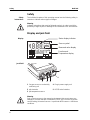
Safety
Safety
instructions
The individual chapters of this operating manual use the following safety in-
struction to indicate various types of danger:
Warning
indicates instructions that must be followed precisely in order to avoid the
possibility of slight injuries or damage to the instrument or the environment.
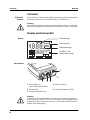
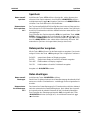
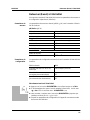
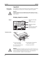
Display and jack field
Display
Jack field
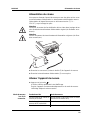
Warning
Only connect sensors to the measuring instrument that cannot return any
voltages or currents that are not allowed (> SELV and > current circuit with
current limiting). Almost all sensors - in particular WTW sensors - fulfill these
conditions.
ARng
Tref20
AutoCal DIN
Lin
TDS
cm
M
°
F
/
K
%
Time
Baud
Day.Month No.
Ident
Year
8
8.
8
8
8
8
°
C
%
mg/l
TP
1
mV/pH
UpH SalO
S
Tref25
nLF
AutoCalTEC
RCL
Auto
Store
LoBat
Cal
AR
1/
cm
Sal
mbar
S/
m
cm
Status display indicator
Measured value display
Function and
Temperature display
Sensor symbol
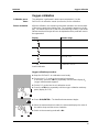
1 Oxygen sensor or conductivity
measuring cell
4 Plug-in power supply unit
2 pH electrode 5 RS232 serial interface
3 pH temperature sensor
5
123
4

Multi 340i Mains power
5
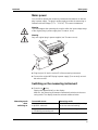
Mains power
You can either operate the measuring instrument with batteries or with the
plug-in power supply. The plug-in power supply provides the measuring in-
strument with low voltage (7.5 V ... 12 V DC). This saves the batteries.
Warning
The line voltage at the operating site must lie within the input voltage range
of the original plug-in power supply (see T
ECHNICAL DATA).
Warning
Only use original plug-in power supplies (see T
ECHNICAL DATA).
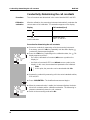
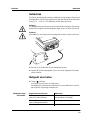
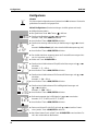
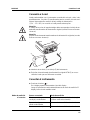
Switching on the measuring instrument
Measuring mode
when
switching on
2
1
3
l Plug the jack (1) into the socket (2) of the measuring instrument.
l Connect the original WTW plug-in power supply (3) to an easily accessi-
ble mains socket.
l Press the <> key.
Display test appears briefly on the display.
After this, the measuring instrument automatically switches to the mea-
suring mode. The display shows the relevant measured value.
Connected sensor Measuring mode
No sensor
or pH/ORP electrode
pH or ORP measurement (depending
on the last selected setting)
Oxygen sensor
or conductivity measuring cell
Last selected measuring mode
2 sensors of any type Last selected measuring mode

Measuring Multi 340i
6
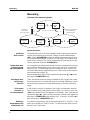
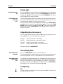
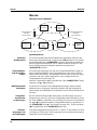
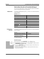
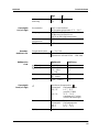
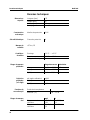
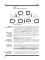
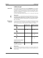
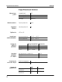
Measuring
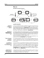
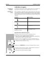
Overview of the measuring modes:
Special functions:
AutoRead
(drift control)
The AutoRead function checks the stability of the measurement signal (ex-
cept for the measurement of the ORP voltage). Activate AutoRead with
<AR>. Press <RUN/ENTER> to start the AutoRead measurement. During
the AutoRead measurement, AR flashes on the display until a stable mea-
sured value is reached. This can be terminated at any time taking over the
current measured value with <RUN/ENTER>.
Temperature mea-
surement during
pH measurements
You can perform pH measurements with or without a temperature sensor as
well as with the temperature sensor of an oxygen sensor or a conductivity
measuring cell. The measuring instrument recognizes which sensors are
connected and switches automatically to the correct mode for the tempera-
ture measurement (display TP).
Manual temperature input: Set the temperature value with <▲> <▼> while
pressing the <RUN/ENTER> key.
AutoRange mea-
suring range
selection
There are several measuring ranges available for both oxygen and conduc-
tivity measurements. If a measuring range is exceeded, AutoRange causes
the measuring instrument to change automatically to the next measuring
range.
Salt content
correction in
O
2
measurements
A salt content correction is required in the oxygen concentration measure-
ment of samples with a salt content of more than 1 g/l. To do so, press the
<CAL> key repeatedly until Sal appears on the display. Then, enter the salt
content with <▲> <▼>. Switch on the salt content correction with <▲> while
pressing the <RUN/ENTER> key (display SAL). To switch it off, press <▼>
while pressing the <RUN/ENTER> key.
Reference
temperature of the
conductivity, Tref
The reference temperature can be switched between 20 °C and 25 °C. It ap-
pears on the display as Tref20 or Tref25. To switchover the reference tem-
perature, see C
ONFIGURING.
Connect or
disconnect
the D.O. probe
or
or
pH value
Redox-
voltage
mV
Connect or disconnect
the conductivity
measuring cell
<M>
<M>
Oxygen
concentration
mg/l
Oxygen
saturation
%
Conductivity
µS/cm
Exchange probe
Salinity
Sal
▲
▼
▲
▼
▲
▼

Multi 340i pH calibration
7
pH calibration
AutoCal TEC This process is specially adapted to the WTW technical buffer solutions as a
fully automatic single or two-point calibration. The buffer solutions are au-
tomatically recognized by the measuring instrument. Depending on the in-
strument setting, the instrument displays the relevant buffer nominal value or
the current electrode voltage in mV.
Valid buffer (values at 25 °C): 2.00 / 4.01 / 7.00 / 10.01
Note
The calibration for pH 10.01 is optimized for the WTW technical buffer solu-
tion TEP 10 Trace or TPL 10 Trace. Other buffer solutions can lead to an er-
roneous calibration. The correct buffer solutions are given in the WTW
catalog or in the Internet.
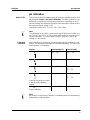
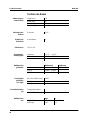
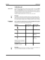
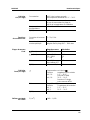
Calibration
evaluation
After calibrating, the measuring instrument automatically evaluates the cali-
bration. The asymmetry and slope are evaluated separately. The worst eval-
uation appears on the display.
Note
If a printer is connected to the interface, a calibration protocol is automatically
printed after a valid calibration.
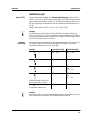
Display Asymmetry[mV] Slope [mV/pH]
-15 ... +15 -60.5 ... -58
-20 ... +20 -58 ... -57
-25 ... +25 -61 ... -60.5
or
-57 ... -56
Clean the electrode according
to the electrode operating
manual
-30 ... +30 -62 ... -61
or
-56 ... -50
E3
Invalid calibration
< -30 or > 30 < -62 or > -50

pH calibration Multi 340i
8
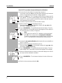
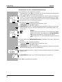
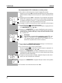
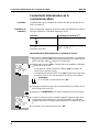
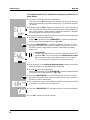
AutoCal TEC procedure (single and two-point calibration):
l Connect the pH electrode to the measuring instrument.
If necessary, press the <M> key until the status display pH (pH measure-
ment) or U (measurement of the ORP voltage) appears.
l Press the <CAL> key. The Ct1 display and the function display AutoCal
TEC appears. The sensor symbol displays the evaluation of the last cal-
ibration (or no sensor symbol in the delivery state or after the measure-
ment parameter has been reset).
l Immerse the pH electrode into the first buffer solution.
l When measuring without a temperature sensor:
Enter the temperature of the first buffer solution with <▲> <▼> while
pressing the <RUN/ENTER> key.
l Press <RUN/ENTER>. The AutoRead measurement begins. The elec-
trode voltage (mV) or the buffer nominal value appears on the display. If
the measured value is stable, Ct2 appears.
Note
At this point, the AutoCal TEC calibration can be terminated
with <M>. This corresponds to a single-point calibration.
To do this, the instrument uses the Nernst slope (-59.2 mV/pH
at 25 °C) and determines the asymmetry of the electrode.
l Immerse the two-point calibration pH electrode in the second buffer so-
lution to continue.
l When measuring without a temperature sensor:
Enter the temperature of the second buffer solution with <▲> <▼> while
pressing the <RUN/ENTER> key.
l Press <RUN/ENTER>. The AutoRead measurement begins. The elec-
trode voltage (mV) or the buffer nominal value appears on the display.
l When the measured value is stable, the instrument displays the value of
the slope and the calibration evaluation.
l Press <RUN/ENTER>. The instrument displays the value of the asym-
metry.
l Switch to the measuring mode with <M>.
8
4
2
t
1
°
C
TP
pH
C
AutoCalTEC
8
4
2
t
2
°
C
TP
pH
C
AutoCalTEC
9
4
pH
5
mV/pH
2
pH
mV

Multi 340i Oxygen calibration
9
Oxygen calibration
Calibration proce-
dures
The calibration is performed in water vapor-saturated air. Use the
OxiCal
®
-SL air calibration vessel (accessories) for the calibration.
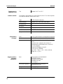
Sensor evaluation After the calibration, the measuring instrument evaluates the current status
of the sensor against the relative slope. The evaluation appears on the dis-
play. The relative slope has no effect on the measuring accuracy. Low values
indicate that the electrolyte will soon be depleted and the probe will have to
be regenerated.
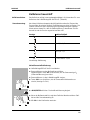
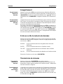
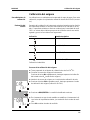
Oxygen calibration procedure:
Display Relative slope
S = 0.8 ... 1.25
S = 0.7 ... 0.8
S = 0.6 ... 0.7
E3
Invalid calibration
S < 0.6 or S > 1.25
l Keep the OxiCal
®
-SL air calibration vessel ready.
l Connect the D. O. probe to the measuring instrument.
If necessary, press the <M> key repeatedly until the status display O
2
(oxygen measurement) appears.
l Put the D. O. probe into the air calibration vessel.
l Press the <CAL> key repeatedly until the oxygen calibration mode ap-
pears (display O
2
CAL).
l Press <RUN/ENTER>. The AutoRead measurement begins.
l When the measured value is stable, the instrument displays the value of
the relative slope and the sensor evaluation.
l Switch to the measuring mode with <M>.
6
7
1
A
L
C
O
°
C
TP
Cal
6
7
1
8
8
0
O
°
C
TP
Cal
AR
S

Conductivity: Determining the cell constants Multi 340i
10
Conductivity: Determining the cell constants
Procedure The cell constants are determined in the control standard 0.01 mol/l KCl.
Calibration
evaluation
After the calibration, the measuring instrument automatically evaluates the
current status of the calibration. The evaluation appears on the display.
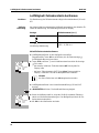
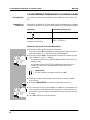
Procedure for determining the cell constants:
Display Cell constant [cm
-1
]
0.450 ... 0.500 cm
-1
E3
Invalid calibration
Outside the range
0.450 ... 0.500 cm
-1
l Connect a conductivity measuring cell to the measuring instrument.
If necessary, press the <M> key repeatedly until the status display
(conductivity measurement) appears.
l Press the <CAL> key. Depending on the calibration status, the CAL
display appears as well as:
– the current, calibrated cell constant (with sensor symbol on the
display) or
– the fixed cell constant 0.475 1/cm (without sensor symbol on the
display). In this case, the measurement parameters are initialized.
Note
At this point, the procedure can be terminated with <M>.
l Immerse the conductivity measuring cell in the control standard solution,
0.01 mol/l KCI.
l Press <RUN/ENTER>. The AutoRead measurement begins.
l When the measured value is stable, the instrument displays the deter-
mined cell constants and the calibration evaluation. The measuring in-
strument automatically stores the cell constants.
l Switch to the measuring mode with <M>.
2
07
4
Cal
cm
1/
Tref25
A
L
C
3
07
4
Cal
cm
1/
Tref25
A
L
C

Multi 340i Saving data
11
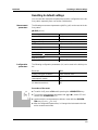
Saving data
Saving data manu-
ally
Press the <STO> key in the measuring mode (display No. with the number of
the next free memory location). Then, press <RUN/ENTER> and enter the ID
number with <▲> <▼>. Terminate the save with <RUN/ENTER>. The instru-
ment changes to the measuring mode.
Saving data auto-
matically
Int 1
The Multi 340i portable measuring instrument has an internal data memory.
It can store up to 500 datasets. The save interval (Int 1) determines the chro-
nological interval between automatic save processes.
To set up the save interval, press <STO> while pressing the <RUN/ENTER>
key (display Int 1) and set the interval with <▲> <▼>key . Then, press <RUN/
ENTER> and enter the ID number with <▲> <▼>. Change to the last active
measuring mode with <RUN/ENTER>. The automatic save is switched on
(display Auto Store).
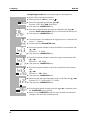
Outputting the data memory
You can output the data memory with the <RCL> key. By repeatedly press-
ing the <RCL> key, you reach the following functions:
Start the output with <RUN/ENTER>.
Transmitting data
Transmitting data
manually
Press the <RUN/ENTER> key in the measuring mode.
This manually triggers a data transmission of the current measured value to
the serial interface at any time - independently of the selected intervals.
Transmitting data
automatically
Int 2
The interval to the data transmission (Int 2) determines the chronological in-
terval between automatic data transmissions. After the selected interval ex-
pires, the current data record is transmitted to the interface. To set up the
transmission interval, press <RCL> while holding down the <RUN/ENTER>
key (display Int 2). Then set the interval with <▲> <▼>.
Configuring
Note
You can leave the configuration menu at any time with <M>. The parameters
already changed are stored.
StO dISP Output stored data on the display
StO SEr Output stored data on the serial interface
CAL dISP Output calibration data on the display
CAL SEr Output calibration data on the serial interface

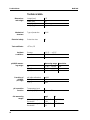
Configuring Multi 340i
12
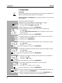
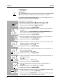
Configuring procedure (factory settings appear in bold typeface):
l Switch off the measuring instrument.
l While pressing the <M> key, press <>.
l Select the required Baud rate with <▲> <▼>.
Selection: 1200, 2400, 4800, 9600 Baud.
l Then press the <RUN/ENTER> key.
l Select the required display during the pH calibration with <▲> <▼>.
Selection: Buffer nominal value (/pH) or current electrode voltage (mV).
l Then press the <RUN/ENTER> key.
l The air pressure is only displayed if an oxygen sensor is connected. Oth-
erwise, "---" appears.
l Continue with the <RUN/ENTER> key.
l Select the required calibration interval for pH/ORP measurements with
<▲> <▼>.
Selection: 1... 7... 999 d.
l Then press the <RUN/ENTER> key.
l Select the required calibration interval for oxygen measurements with
<▲> <▼>.
Selection: 1... 14... 999 d.
l Then press the <RUN/ENTER> key.
l Select the required calibration interval for conductivity measurements
with
<▲> <▼>.
Selection: 1... 180... 999 d.
l Then press the <RUN/ENTER> key.
l Switchover the reference temperature of the conductivity with <▲> <▼>.
Selection: 25 °C (Tref25) and 20 °C (Tref20).
l Then press the <RUN/ENTER> key.
l Select the date and time step-by-step with <▲> <▼>. In between, press
the <RUN/ENTER> key each time.
l When the last <RUN/ENTER> key has been pressed, the instrument
changes to the last active measuring mode.
Baud
0
40
8
p
ds
i
A
L
C
/pH
pH
mbar
9
4
9
p
Time
7
d
T
3
n
1
pH
Time
4
d
T
4
n
1
1
O
Time
0
d
T
5
n
1
8
1
Tref25
2
5
t
Day.Month
4
00
9

Multi 340i Resetting to default settings
13
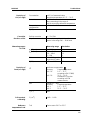
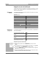
Resetting to default settings
You can reset the measurement parameters and the configuration to the de-
livery status separately from one another (initialization).
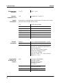
Measurement
parameters
The following measurement parameters (pH/O
2
/ InI) can be reset to the de-
livery status:
Configuration
parameters
The following configuration parameters (InI) can be reset to the delivery sta-
tus:
Procedure of the reset:
pH/ORP (pH InI)
Measuring mode pH
Asymmetry 0 mV
Slope -59.16 mV
Oxygen (O
2
InI)
Measuring mode D. O. concentration
Relative slope 1.00
Salinity (value) 0.0
Salinity (function) off
Conductivity ( InI)
Measuring mode
Cell constant 0.475 cm
-1
Baud rate 4800
Display during pH calibration Buffer nominal value
Interval 1
(automatically saved) OFF
Interval 2
(for data transmission) OFF
l To switch it off, press <CAL> while pressing the <RUN/ENTER> key.
l To reset the measurement parameters with <▲> <▼>, select YES and
confirm with <RUN/ENTER>, or
l continue with the next parameters without a reset with the <RUN/EN-
TER> key (O
2
InI > InI > InI).
l After the configuration parameters, InI changes the instrument to the last
active measurement mode.
o
n
n
i
i
pH

Technical data Multi 340i
14
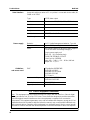
Technical data
Dimensions
and weight
Mechanical
structure
Electrical safety
Test certificates
Ambient
conditions
pH/ORP measur-
ing ranges
Precision of
pH/ORP
(± 1 digit)
pH correction
function
Oxi measuring
ranges
Length [mm] 172
Width [mm] 80
Height [mm] 37
Weight [kg] approx. 0.3
Type of protection IP 66
Protective class III
cETLus, CE
Storage - 25 °C ... + 65 °C
Operation -10 °C ... + 55 °C
Climatic class 2
Measuring range Resolution
pH - 2.00 ... + 19.99 0.01
U [mV] - 1999 ... + 1999 1
T [°C] - 5.0 ... + 105.0 0.1
pH (after calibration) ± 0.01
U [mV] ± 1
T [°C] ± 0.1
Temperature input
Manually [°C] - 20 ... + 130
mg/l %
Measuring range I
Resolution
0 ... 19.99
0.01
0 ... 199.9
0.1
Measuring range II
Resolution
0 ... 90.0l
0.1
0 ... 600
1

Multi 340i Technical data
15
Precision of
Oxi (± 1 digit)
Correction
functions of Oxi
Measuring ranges
of Cond
Precision of
Cond (± 1 digit)
Cell constant,
calibrating
Reference
temperature Cond
Concentration ± 0.5 % of measured value
at ambient temperature of 5 °C ... 30 °C
Saturation ± 0.5 % of measured value
when measuring in the range of
± 10 K around the calibration temperature
Temperature
compensation
< 2 % at 0 ... 40 °C
T [°C] ± 0.1
Salinity correction 0 ... 70.0 SAL
Air pressure correction Automatic through installation of pressure
sensor in the range 500 ... 1100 mbar
Measuring range Resolution
[µS/cm] 0 ... 1999 1
[mS/cm] 0.00 ... 19.99
0.0 ... 199.9
0 ... 500
0.01
0.1
1
SAL 0.0 ... 70.0 accord-
ing to the IOT table
0.1
T [°C]
− 5.0 ... + 105.0 0.1
Nonlinear compensation
Accuracy Sample temperature
± 0.5 % 0 °C ... 35 °C
according to EN 27 888;
± 0.5 % 35 °C ... 50 °C
extended nLF function
according to WTW
measurements
SAL Range 0.0 ... 42.0
Accuracy Sample temperature
± 0.1 5 °C ... 25 °C
± 0.2 25 °C ... 30 °C
T [°C] ± 0.1
C [cm
-1
] 0.450 ... 0.500
Tref Can be set to 20 °C or 25 °C

Technical data Multi 340i
16
Serial interface Automatic switchover when a PC or a printer is connected via the cable, AK
340/B or AK 325/S.
Power supply
Guidelines
and norms used
Type RS232, data output
Baud rate Can be set to 1200, 2400, 4800, 9600 Baud
Data bits 8
Stop bit 2
Parity None
Handshake RTS/CTS + Xon/Xoff
Cable length Max. 15 m
Batteries 4 x 1.5 V alkali-manganese batteries, Type AA
Operational life approx. 3000 operating hours
Mains The following applies to all plug-in power supplies:
Connection max. overvoltage category II
Plug-in power supply unit
(Euro, US , UK, Australian plug)
FRIWO FW7555M/09, 15.1432
Friwo Part. No. 1822089
Input: 100 ... 240 V ~ / 50 ... 60 Hz / 400 mA
Output: 9 V = / 1,5 A
EMC EG guideline 89/336/EWG
EN 61326 A1:1998
EN 61000-3-2 A14:2000
EN 61000-3-3:1995
FCC Class A
Instrument safety EG guideline 73/23/EWG
EN 61010-1 A2:1995
Climatic class VDI/VDE 3540
Type of protection EN 60529:1991
FCC Class A Equipment Statement
Note: This equipment has been tested and found to comply with the limits for a Class A digital
device, pursuant to Part 15 of the FCC Rules. These limits are designed to provide reasonable
protection against harmful interference when the equipment is operated in a commercial
environment. This equipment generates, uses, and can radiate radio frequency energy and, if not
installed and used in accordance with the instruction manual, may cause harmful interference to
radio communications. Operation of this equipment in a residential area is likely to cause harmful
interference in which case the user will be required to correct the interference at his own expense.

Multi 340i Inhaltsverzeichnis
17
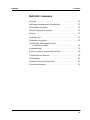
Multi 340i - Inhaltsverzeichnis
Sicherheit . . . . . . . . . . . . . . . . . . . . . . . . . . . . . . . . . . . . . . . . 18
Display und Buchsenfeld . . . . . . . . . . . . . . . . . . . . . . . . . . . . 18
Netzbetrieb. . . . . . . . . . . . . . . . . . . . . . . . . . . . . . . . . . . . . . . 19
Meßgerät einschalten. . . . . . . . . . . . . . . . . . . . . . . . . . . . . . . 19
Messen. . . . . . . . . . . . . . . . . . . . . . . . . . . . . . . . . . . . . . . . . . 20
Kalibrieren pH. . . . . . . . . . . . . . . . . . . . . . . . . . . . . . . . . . . . . 21
Kalibrieren Sauerstoff. . . . . . . . . . . . . . . . . . . . . . . . . . . . . . . 23
Leitfähigkeit: Zellenkonstante bestimmen . . . . . . . . . . . . . . . 24
Speichern . . . . . . . . . . . . . . . . . . . . . . . . . . . . . . . . . . . . . . . . 25
Datenspeicher ausgeben . . . . . . . . . . . . . . . . . . . . . . . . . . . . 25
Daten übertragen . . . . . . . . . . . . . . . . . . . . . . . . . . . . . . . . . . 25
Konfigurieren . . . . . . . . . . . . . . . . . . . . . . . . . . . . . . . . . . . . . 26
Rücksetzen (Reset) auf Grundeinstellungen . . . . . . . . . . . . . 27
Technische Daten . . . . . . . . . . . . . . . . . . . . . . . . . . . . . . . . . 28

Sicherheit Multi 340i
18
Sicherheit
Sicherheits-
hinweise
In den einzelnen Kapiteln dieser Bedienungsanleitung weisen die folgenden
Sicherheitshinweise auf verschiedene Stufen von Gefahren hin:
Achtung
kennzeichnet Hinweise, die genau beachtet werden müssen, um mögliche
leichte Verletzungen oder Schäden am Gerät oder der Umwelt zu vermeiden.
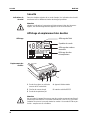
Display und Buchsenfeld
Display
Buchsenfeld
Achtung
Schließen Sie an das Meßgerät nur Sensoren an, die keine unzulässigen
Spannungen oder Ströme (> SELV und > Stromkreis mit Strombegrenzung)
einspeisen können. Nahezu alle Sensoren - insbesondere WTW-Sensoren -
erfüllen diese Bedingungen.
ARng
Tref20
AutoCal DIN
Lin
TDS
cm
M
°
F
/
K
%
Time
Baud
Day.Month No.
Ident
Year
8
8.
8
8
8
8
°
C
%
mg/l
TP
1
mV/pH
UpH SalO
S
Tref25
nLF
AutoCalTEC
RCL
Auto
Store
LoBat
Cal
AR
1/
cm
Sal
mbar
S/
m
cm
Statusanzeige
Meßwertanzeige
Funktions- und
Temperaturanzeige
Sensorsymbol
1 Sauerstoffsensor
oder Leitfähigkeitsmeßzelle
4 Steckernetzgerät
2 pH-Meßkette 5 Serielle Schnittstelle RS232
3 Temperaturmeßfühler pH
5
123
4

Multi 340i Netzbetrieb
19
Netzbetrieb
Sie können das Meßgerät wahlweise mit Batterien oder mit dem Steckernetz-
gerät betreiben. Das Steckernetzgerät versorgt das Meßgerät mit Kleinspan-
nung (7,5 V ... 12 V DC). Die Batterien werden dabei geschont.
Achtung
Die Netzspannung am Einsatzort muß innerhalb des Eingangs-Spannungs-
bereichs des Original-Steckernetzgeräts liegen (siehe T
ECHNISCHE DATEN).
Achtung
Verwenden Sie nur Original-Steckernetzgeräte (siehe T
ECHNISCHE DATEN).
Meßgerät einschalten
Meßmodus beim
Einschalten
2
1
3
l Stecker (1) in die Buchse (2) des Meßgeräts stecken.
l Original WTW-Steckernetzgerät (3) an eine leicht zugängliche Steckdo-
se anschließen
l Taste <> drücken.
Im Display erscheint kurz der Displaytest.
Das Meßgerät schaltet danach automatisch in den Meßmodus. Das Dis-
play zeigt den zugehörigen Meßwert an.
Angeschlossener Sensor Meßmodus
Kein Sensor
oder pH-/Redox-Meßkette
pH- oder Redoxmessung (je nach zu-
letzt gewählter Einstellung)
Sauerstoffsensor
oder Leitfähigkeitsmeßzelle
zuletzt eingestellter Meßmodus
2 beliebige Sensoren zuletzt eingestellter Meßmodus

Messen Multi 340i
20
Messen
Überblick über die Meßmodi:
Spezialfunktionen:
AutoRead
(Driftkontrolle)
Die Funktion AutoRead prüft die Stabilität des Meßsignals (außer bei der
Messung bei Redoxspannung). AutoRead mit <AR> aktivieren. Zum Starten
der AutoRead-Messung <RUN/ENTER> drücken. Während der AutoRead-
Messung blinkt die Anzeige AR, bis ein stabiler Meßwert vorliegt. Ein Ab-
bruch mit Übernahme des aktuellen Meßwerts ist jederzeit mit
<RUN/ENTER> möglich.
Temperaturmes-
sung bei pH-Mes-
sungen
Sie können pH-Messungen mit und ohne Temperaturmeßfühler sowie mit
dem Temperaturmeßfühler eines Sauerstoffsensors oder einer Leitfähig-
keitsmeßzelle durchführen. Das Meßgerät erkennt, welche Sensoren ange-
schlossen sind und schaltet automatisch in den richtigen Modus der
Temperaturmessung (Anzeige TP).
Manuelle Temperatureingabe: Bei gedrückter Taste <RUN/ENTER> Tempe-
raturwert mit <▲> <▼> einstellen.
Meßbereichswahl
AutoRange
Es stehen für Sauerstoff- und Leitfähigkeitsmessungen jeweils mehrere
Meßbereiche zur Verfügung. AutoRange bewirkt, daß das Meßgerät bei
Überschreiten eines Meßbereichs automatisch in den nächsten Meßbereich
wechselt.
Salzgehalts-
korrektur bei
O
2
-Messungen
Bei der Sauerstoff-Konzentrationsmessung von Meßlösungen mit einem
Salzgehalt von mehr als 1 g/l ist eine Salzgehaltskorrektur erforderlich. Dazu
die Taste <CAL> so oft drücken, bis im Display Sal erscheint. Anschließend
mit <▲> <▼> Salzgehalt eingeben. Salzgehaltskorrektur bei gedrückter Ta-
ste <RUN/ENTER> mit <▲> einschalten (Anzeige SAL). Zum Ausschalten
<▼> bei gedrückter Taste <RUN/ENTER> drücken.
Referenz-
temperatur Tref
der Leitfähigkeit
Die Referenztemperatur ist zwischen 20 °C und 25 °C umschaltbar. Sie wird
im Display mit Tref20 oder Tref25 angezeigt. Zum Umschalten der Referenz-
temperatur siehe K
ONFIGURIEREN.
Sauerstoffsensor
verbinden
bzw. abstecken
oder
oder
pH-Wert
Redox-
spannung
mV
Leitfähigkeitsmeßzelle
verbinden
bzw. abstecken
<M>
<M>
Sauerstoff-
konzentration
mg/l
Sauerstoff-
sättigung
%
Leitfähigkeit
µS/cm
Sensor wechseln
Salinität
Sal
▲
▼
▲
▼
▲
▼
La page est en cours de chargement...
La page est en cours de chargement...
La page est en cours de chargement...
La page est en cours de chargement...
La page est en cours de chargement...
La page est en cours de chargement...
La page est en cours de chargement...
La page est en cours de chargement...
La page est en cours de chargement...
La page est en cours de chargement...
La page est en cours de chargement...
La page est en cours de chargement...
La page est en cours de chargement...
La page est en cours de chargement...
La page est en cours de chargement...
La page est en cours de chargement...
La page est en cours de chargement...
La page est en cours de chargement...
La page est en cours de chargement...
La page est en cours de chargement...
La page est en cours de chargement...
La page est en cours de chargement...
La page est en cours de chargement...
La page est en cours de chargement...
La page est en cours de chargement...
La page est en cours de chargement...
La page est en cours de chargement...
La page est en cours de chargement...
La page est en cours de chargement...
La page est en cours de chargement...
La page est en cours de chargement...
La page est en cours de chargement...
La page est en cours de chargement...
La page est en cours de chargement...
La page est en cours de chargement...
La page est en cours de chargement...
La page est en cours de chargement...
La page est en cours de chargement...
-
 1
1
-
 2
2
-
 3
3
-
 4
4
-
 5
5
-
 6
6
-
 7
7
-
 8
8
-
 9
9
-
 10
10
-
 11
11
-
 12
12
-
 13
13
-
 14
14
-
 15
15
-
 16
16
-
 17
17
-
 18
18
-
 19
19
-
 20
20
-
 21
21
-
 22
22
-
 23
23
-
 24
24
-
 25
25
-
 26
26
-
 27
27
-
 28
28
-
 29
29
-
 30
30
-
 31
31
-
 32
32
-
 33
33
-
 34
34
-
 35
35
-
 36
36
-
 37
37
-
 38
38
-
 39
39
-
 40
40
-
 41
41
-
 42
42
-
 43
43
-
 44
44
-
 45
45
-
 46
46
-
 47
47
-
 48
48
-
 49
49
-
 50
50
-
 51
51
-
 52
52
-
 53
53
-
 54
54
-
 55
55
-
 56
56
-
 57
57
-
 58
58


wtw Cond 3400i Mode d'emploi
- Catégorie
- Mesure, test
- Taper
- Mode d'emploi
- Ce manuel convient également à
dans d''autres langues
- English: wtw Cond 3400i Operating instructions
- español: wtw Cond 3400i Instrucciones de operación
- Deutsch: wtw Cond 3400i Bedienungsanleitung
Documents connexes
Autres documents
-
Hach sensION+ MM150 Manuel utilisateur
-
 Hach H160 Manuel utilisateur
-
Consort C3430 Manuel utilisateur
-
 Thermo Fisher Scientific Elite CTS Tester Mode d'emploi
-
Omega RH202 and RH-202L Le manuel du propriétaire
-
Davey Regulmatic Le manuel du propriétaire
-
Wohler WA 335 Manuel utilisateur
-
 Teledyne 3190 Manuel utilisateur
-
YSI TruLine ORP 50 Electrode Le manuel du propriétaire


