
66403100 06/2005
Inst allat ion, Operat ing and
Servicing Instructions
excellence in hot water
TER

66403100 06/2005 Page 2
1. PRODUCT DESCRIPTION
Medium-power, heating only boiler, for industrial and commercial applications
Boiler body manufactured out of STW22 carbon steel plates
Stylish metal casing, painted red
Replaceable heating elements
Rigid polyurethane foam insulation
Control panel, complete with
- main switch
- 4 power stages status lights
- overheating warning lights
- boiler temperature thermometer
- boiler control thermostat adjustable between 30 and 90°C
- overheating safety thermostat, to be resetted manually
Available in 5 models between 57 and 259 kw
2. CONSTRUCTION FEATURES
BOILER BODY
Manufactured out of ST37 high-thickness steel. The boiler body is submitted to a
hydraulic test pressure of 6 bars (the maximum allowable working pressure is 4 bars).
HEATING ELEMENTS
Replaceable elements, mounted on the front of the boiler body with a pressure gasket. The
heating elements are made out of Incoloy stainless steel, with a specific thermal
load of 12.9 W/cm².
ELECTRICAL CONNECTION PANEL
The panel is equipped with:
- Power terminal board for three-phase power supply (400 V + N)
- Control circuit terminal board for single-phase 230 V power supply
- Grounding terminal
- Four power contactor groups
- 4-power stage cascade programmer
- Fast cut-off relay
- Programmer resetting relay
INSULATION
CFC-free, 50 mm thick rigid polyurethane foam insulation.
CASING
The casing is entirely made out of steel plates and submitted to degreasing and phosphating before
epoxy-powder painting. After painting, the panels are baked at 220°C. This coating guarantees a
good resistance and a perfect finish.
PACKAGING
A special packaging has been designed for the vertical transport of the unit.
The boiler is wrapped in shrink wrap film to protect it against scratches and to make any
damage caused during transport immediately visible.

66403100 06/2005 Page 3
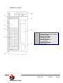
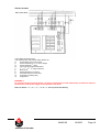
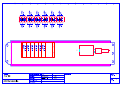
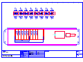
GENERAL LAYOUT
1. Boiler body
2. rigid polyurethane foam insulation
3. Enameled casing
4. Heating water supply
5. Heating water return
6. Heating elements
7. Cascade programmer
8. Electrical panel
9. Connection terminals
10. Control panel

66403100 06/2005 Page 4
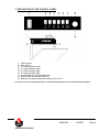
3. DESCRIPTION OF THE CONTROL PANEL
1) Thermometer
2) Main switch
3) 1
st
stage operation light
4) 2
nd
stage operation light
5) 3
th
stage operation light
6) 4
th
stage operation light
7) Overheating lock-out indicating light
8) Boiler control thermostat (30-90°C)
9) Manually resettable safety thermostat, set at 103 °C
To access to the connection terminals, unscrew the two screws "A" and remove the front panel.

66403100 06/2005 Page 5
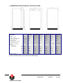
4. DIMENSIONS AND TECHNICAL SPECIFICATIONS
TYPE
TER 57 TER 86 TER 115 TER 144 TER 201 TER 259
Partnumber
00080401 000080801 00081201 00081601 00079101 00079901
Power kW 57,6 86,4 115,2 144 201,6 259,2
Power voltage V 3x400 + N 3x400 + N 3x400 + N 3x400 + N 3x400 + N 3x400 + N
Control circuit voltage V 230 230 230 230 230 230
Heating elements nombre 12 x 2 18 x 2 24 x 2 30 x 2 42 x 2 54 x 2
Total capacity L 155 155 155 155 250 250
Working pressure (max) bar 4 4 4 4 4 4
Temperature (max) °C 90 90 90 90 90 90
Heating connection
(female)
ø 2” 2” 2” 2” DN 100* DN 100*
Dimensions A mm 80 80 80 80 80 80
B mm 124 124 124 124 190 190
C mm 1134 1134 1134 1134 1060 1060
D mm 130 130 130 130 197 197
E mm 610 610 610 610 752 752
F mm 1380 1380 1380 1380 1380 1380
G mm 610 610 610 610 752 752
Weigth (empty) Kg 102 102 102 102 195 195
(*) Above 144 kW, heating circuit connection with DN 100 flange.

66403100 06/2005 Page 6
5. SIZING OF SUPPLY WIRES
The supply wires are sized depending of the type and current of the MCB. This last is sized
depending of the nominal current of the boiler. The admissible current of the supply wires depends
of the ambient temperature, the section, the length and the insulation of the wires, the wires ducts,
the mounting and the environment.
The following values are given for information for an ambient temperature of 25°C and a maximal
length of 5 meters. In all the circumstances, the installation must be in accordance with the current
IEE wiring regulations.
For higher temperatures, the current rating should be reduced according to the next table:
6. POWER CHARACTERISTICS: V 400/3/50 + N
Power, per stage kW
Amperes, per stage, at V 400/3/50
Type
Total power 1° 2° 3° 4° 1° 2° 3° 4°
Amperes
total
kW Stage Stage Stage Stage Stage Stage Stage Stage
TER 57
57,6 14,4
14,4
14,4 14,4 20,9 20,9 20,9 20,9 84
TER 86
86,4 21,6 21,6 21,6 21,6 31,3 31,3 31,3 31,3 125
TER 115
115,2 28,8 28,8 28,8 28,8 41,7
41,7
41,7
41,7
167
TER 144
144,0 36,0 36,0 36,0 36,0 52,2 52,2 52,2 52,2 209
TER 201
201,6 50,4 50,4 50,4 50,4 73 73 73 73 292
TER 259
259,2 64,8 64,8 64,8 64,8 94 94 94 94 376
Diametre
mm
2
0,8 1 1,5 2,5 4,6 10 16 25 35 50 70 95 120 150 185 240
current Amp 13 16 20 27 36 47 65 87 115 143 178 220 265 310 355 480
T
ambient
°C 25 30 35 40 45 50 55
Current derating % 100 92 85 75 65 53 38

66403100 06/2005 Page 7
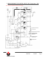
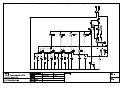
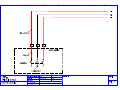
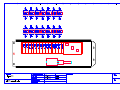
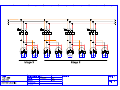
D
Safety power relay (not
supplied by ACV)
Terminal for external
safety power relay (not
supplied by ACV)
Terminals for remote
indicators of the power
stages (230 V)
Fast cutoff relay
Programmer resetting relay
D
Microswitches of the programm
e
Safety
thermostat
Control thermostat
30 – 90 °C
Programmer motor
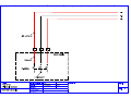
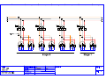
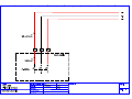
7. WIRING DIAGRAM OF THE CONTROL CIRCUIT 230V / Single phase / 50Hz
TER > V05: see schematics at the end of this manual

66403100 06/2005 Page 8
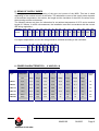
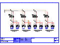
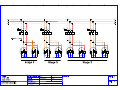
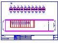
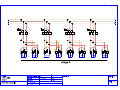
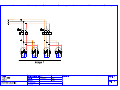
8. WIRING DIAGRAM OF THE CASCADE PROGRAMMER
FEEDRATE OF THE PROGRAMMER : 5 SECONDS PER GRADE

66403100 06/2005 Page 9
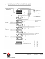
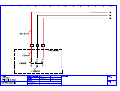
9. HYDRAULIC AND ELECTRICAL CONNECTIONS
230 V
Warning !!! In order to ensure the proper
functioning of the safety thermostat, it is
mandatory to connect the phase / neutral
the
right way
1) Controller
2) Climatic sensor
3) Overheating safety thermostat, interrupting the power
relays and powering the reset relay
4) Supply thermo-sensor
NB: the listed devices are not supplied by ACV.
01 CONTROLLED BY CLIMATIC SENSOR
02 STABILIZED TEMPERATURE CONTROL
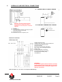
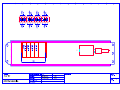
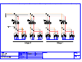
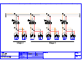
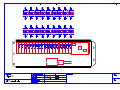
Electrical connection
TER 57 up to 144
b) Boiler protection fuses
d) Safety relay with positive safety release coil
e) Control circuit protection fuses
g) Power terminals
h) Control circuit terminals 230V 50Hz
i) 1st – 2nd – 3rd – 4th stage contactors
j) Main circuit
k) Heating elements 2 x 2400 W
l) Control circuit main cut-out relay
m) Programmer resetting relay
n) Programmer
CAUTION!! For electrical safety reasons, it is
recommended to always install differential
cut-out devices on the power supply circuits.
WARNING !!!
For protection against electrical hazard, it is always
recommended to install a differential cut-out device
(Ground Fault Isolator) on the power supply circuit,
upstream of the boiler.
N.B. The devices "b", "d" and "e" are not part of ACV delivery
.

66403100 06/2005 Page 10
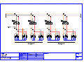
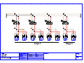
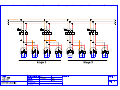
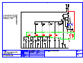
TER 201 and 259
a) et b) Boiler protection fuses
c) et d) Safety relay with positive safety release coil
e) On/off switch of the control circuit
f) Power terminals for 2
d
, 3
th
and 4
th
stages
g) Power terminals 1
st
stage
h) Control circuit terminals 230V 50Hz
i) 1
st
– 2
nd
– 3
th
– 4
th
stage contactors
j) Main circuit
k) Heating elements 2 x 2400 W
l) Control circuit main cut-out relay
m) Programmer resetting relay
n) Programmer
WARNING !!!
For protection against electrical hazard, it is always recommended to install a differential cut-out device (Ground
Fault Isolator) on the power supply circuit, upstream of the boiler
N.B. The devices “ a ” ,“ b ” ,“ c ” ,“ d ” et “ e ” are not part of ACV delivery

66403100 06/2005 Page 11
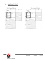
10. MAINTENANCE SPACE
TER 57 up to TER 144 TER 201 and TER 259
610
124
500
610 700

66403100 06/2005 Page 12
11. INSTALLATION
WARNING !!! Size the flowrate in the hydraulic circuit to ensure a 10°C maximum ∆t.
GENERAL SAFETY RULES :
The boiler must be installed by an registered company.
After the installation work, the installer must issue a statement of compliance, declaring that the
installation has been carried out in a workmanlike manner, as defined for by the applicable
regulations.
Make sure that the wiring system and the power input lines are designed and installed by
skilled engineers in compliance with the applicable regulations.
IMPORTANT
As far as the power input to the boiler is concerned, the installation must comply with IEC 364
standards and other provisions concerning installation conditions.
For protection against electrical hazard, it is always recommended to install a differential
cut-out device (Ground Fault Isolator) on the power supply circuit, upstream of the boiler.
For protection against overheating, it is advisable to place a positive safety electric power
cut-out, controlled by the boiler safety thermostat.
BOILER ROOM
Electric boilers must be installed in boiler rooms complying with the technical standards
and applicable regulations.
The appliance should never be installed outdoors, because it has not been designed for
and is not equipped with automatic defrosting systems.
If possible, install the boiler above the ground level, to reduce the risk of flooding the
electrical components.
INSTALLATION ON AN EXISTING HEATING CIRCUIT
If you connect the boiler on an existing heating circuit, please carefully check that:
The pump is powerful enough and in good shape.
The boiler room is clean and ventilated.
The expansion vessel is sized to absorb the heat expansion of the complete heating circuit.
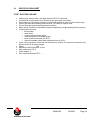
12. COMMISSIONING
PREPARATION BEFORE COMMISSIONING
Before powering up the boiler and performing the functional tests, make sure that:
the hydraulic circuit valves are opened;
the electric power is available;
the pressure of the (cold) hydraulic circuit is higher than 1 bar and lower than the maximum
working pressure of the appliance;
the hydraulic circuits have been througoutly purged: pump the heating fluid through the
hydraulic circuit and purge the air from the installation
the electric connection to the power mains and the external control connection have
been carefully carried out;
the grounding connections have been installed as specified by local regulations
13. MAINTENANCE
Check on a regular base that the heating circuit pressure is higher than 1 bar.
If the pressure drops below 1 bar, please contact your installer
DON'T SWAP THE PHASE / NEUTRAL CONNECTIONS.
GROUNDING CONNECTION IS MANDATORY

66403100 06/2005 Page 13
14. SPECIFICATION SHEET
"TER" ELECTRIC BOILER
• Heating-only electric boiler, with high-thickness ST37/2 steel body
• Connections to the heating circuit located at the upper part of the boiler
• Removable 2.4 kW heating elements mounted with gaskets to the front of the boiler body
• Incolloy stainless steel heating elements with 12.9 W/sq.cm specific load
• 50 mm thick rigid projected polyurethane insulation
• Metal casing, stoved and submitted to special degreasing and phosphating before painting
• Control panel including:
o thermometer
o main switch
o 4 power stage indicator lights
o overheating lock-out indicating light
o boiler control thermostat (30-90°C)
o manual resetable safety thermostat factory set at 103°C.
• Cyclic cam-programmer motor with two directions of rotation, for automatic connection and
disconnection of the power stages.
• Power: ……………….. KW
• Maximum working pressure: 4 bars
• Max temperature: 90°C
• Power stages: 4
• ACV trade-mark Model TER ………

66403100 06/2005 Page 14
15. LISTE DES PIECES DE RECHANGE TER 57-259 SPARE PARTS LIST
Description en français Code English denomination
Résistance 2 x 2,4 kW 54428182 Immersion heater 2 x 2,4 kW
Relais de puissance 20 Amp 54452082 Power relay 20 Amp
Programmateur Crouzet 10 contacts 54452095 Timer Crouzet 10 contacts
Condensateur moteur de programmateur 54429014 Condensator for timer-motor
Relais 3 inverseurs 230 V 10 A 54428220 Reverse relay 230 V 10 A
Thermostat de commande à bulbe 30 à 90 °C 54442045 Control thermostat with bulb 30-90°C
Interrupteur bipolaire lumineux 54428116 Switch, double pole, with indicator light
Thermostat à réarmement 54764009 Safety thermostat with manual reset
Thermomètre vertical à capillaire 1,5 m 54441012 Thermometer vertical with capilair 1.5 m
Lampe témoin rouge 54428203 Indicator light red
Lampe témoin verte 54766000 Indicator light green
Borne 70 mm² 54428242 Terminal block 70mm²
Borne 150 mm² 54428244 Terminal block 150mm²
Borne 240 mm² 54428245 Terminal block 240mm²
Jacquette TER 57 -144 (ensemble) 21470058 Housing TER 57 -144 (complete set)
Latérale droite 21471058 Right panel
Latérale gauche 21472058 Left panel
Porte avant 21473058 Front door
Tôle arrière 21474058 Back panel
Couvercle 21475058 Top panel
Tableau de commande (tôle non câblée) 21477058 Control Panel (panel only)
Tableau de commande (câblé) 257F1051 Control Panel (complete)
Jacquette TER 201 -259 (ensemble) 21470059 Housing TER 201-259 (complete set)
Latérale droite 21471059 Right panel
Latérale gauche 21472059 Left panel
Porte avant 21473059 Front door
Tôle arrière 21474059 Back panel
Couvercle 21475059 Top panel
Tableau de commande (tôle non câblée) 21477059 Control Panel (panel only)
Tableau de commande (câblé) 257F1052 Control Panel (complete)
Borniers – Terminal blocks
TER 57 à 115 (4x150 mm²) 54428244
TER 144 (3x150 mm²) 54428244
(1x240 mm² pour le neutre) 54428245
TER 201 (4x240 mm²) 54428245
4x70 mm2 pour le premier étage 54428242
TER 259 (4x240 mm²) 54428245
4x150 mm² pour le premier étage 54428244


La page est en cours de chargement...
La page est en cours de chargement...
La page est en cours de chargement...
La page est en cours de chargement...
La page est en cours de chargement...
La page est en cours de chargement...
La page est en cours de chargement...
La page est en cours de chargement...
La page est en cours de chargement...
La page est en cours de chargement...
La page est en cours de chargement...
La page est en cours de chargement...
La page est en cours de chargement...
La page est en cours de chargement...
La page est en cours de chargement...
La page est en cours de chargement...
La page est en cours de chargement...
La page est en cours de chargement...
La page est en cours de chargement...
La page est en cours de chargement...
La page est en cours de chargement...
La page est en cours de chargement...
La page est en cours de chargement...
La page est en cours de chargement...
-
 1
1
-
 2
2
-
 3
3
-
 4
4
-
 5
5
-
 6
6
-
 7
7
-
 8
8
-
 9
9
-
 10
10
-
 11
11
-
 12
12
-
 13
13
-
 14
14
-
 15
15
-
 16
16
-
 17
17
-
 18
18
-
 19
19
-
 20
20
-
 21
21
-
 22
22
-
 23
23
-
 24
24
-
 25
25
-
 26
26
-
 27
27
-
 28
28
-
 29
29
-
 30
30
-
 31
31
-
 32
32
-
 33
33
-
 34
34
-
 35
35
-
 36
36
-
 37
37
-
 38
38
-
 39
39
-
 40
40
-
 41
41
-
 42
42
-
 43
43
-
 44
44


