Baxi Luna 3 Comfort 310 Fi Installation And Servicing Instructions
- Catégorie
- Chauffe-eau
- Taper
- Installation And Servicing Instructions
Ce manuel convient également à

BAXI S.p.A. , l’une des entreprises leader en Europe dans la production d’appareils de chauffage et sanitaires à usage domestique,
(chaudières murales à gaz, chaudières au sol, chauffe-eau électriques, plaques de chauffe en acier), a obtenu la certication CSQ de
conformité aux normes UNI EN ISO 9001. Ce certicat assure que le Système de Qualité en usage aux usines BAXI S.p.A. de Bassano
del Grappa, où l’on a produit cette chaudière, satisfait la plus sévère des normes - c’est-à-dire la UNI EN ISO 9001 - qui concerne tous
les stades d’organisation et le personnel intéressé du procès de production et distribution.
BAXI S.p.A., one of the leading European enterprises to produce central heating and hot water devices for domestic use (wall-moun-
ted gaz-operated boilers, oor-standing boilers, electrical water-heaters and steel heating plates) has obtained the QSC certicate of
conformity to the UNI EN ISO 9001 norms. This certicate guarantees that the Quality System applied at the BAXI S.p.A. factory in
Bassano del Grappa, where your boiler was produced, meets the standards of the UNI EN ISO 9001 norm, which is the strictest and
concerns all organization stages and operating personnel involved in the production and distribution processes.
UNI EN ISO 9001
CERTIFICAZIONE DEI SISTEMI
QUALITA' DELLE AZIENDE
High efficiency gas fired wall mounted combination boiler
Chaudière murale à gaz à rendement élevé
Installation and servicing instructions
Notice d’installation et d’entretien
WARNING: If the information in these instructions
is not followed exactly, a re or explosion may result
causing property damage, personal injury or death.
— Do not store or use gasoline or other ammable
vapors and liquids in the vicinity of this or any
other appliance.
— WHAT TO DO IF YOU SMELL GAS
• Do not try to light any appliance.
• Do not touch any electrical switch; do not use
any phone in your building.
• Immediately call your gas supplier from a
neighbor’s phone. Follow the gas supplier’s
instructions.
• If you cannot reach your gas supplier, call the
re department.
— Installation and service must be performed by a
qualied installer, service agency or the gas sup-
plier.
AVERTISSEMENT: Assurez-vous de bien suivre les instruc-
tions dennées dans cette notice pour réduire au minimum le
risque d’incendie ou d’explosion ou pour éviter tout dom-
mage matériel, toute blessure ou la mort.
— Ne pas entreposer ni utiliser d’essence ou ni d’autres
vapeurs ou liquides inammables à proximité de cet
appareil ou de tout autre appareil.
— QUE FAIRE SI VOUS SENTEZ UNE ODEUR DE GAZ
• Ne pas tenter d’allumer d’appareil.
• Ne touchez à aucun interrupteur; ne pas vous
servir des téléfhones se trouvant dans le bâtiment.
• Appelez immédiatement votre fournisseur de gaz
depuis un voisin.
Suivez les instructions du fournisseur.
• Si vous ne pouvez rejoindre le fournisseur, appelez
le service des incendies.
— L’installation et l’entretien doivent être assurés par un
installateur ou un service d’entretien qualié ou par le
forunisseur de gaz.

2
925.188.3 - GB
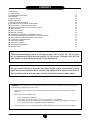
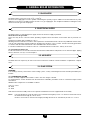
INSTRUCTIONS PERTAINING TO THE INSTALLER
1. Introduction 3
2. Technical data 4
3. General boiler information 10
4. Installation 19
5. Commissioning 21
6. Boiler operation 25
7. Remote control installation 26
8. Connection of the external sensor probe 27
9. Connecting an external hot water tank 28
10. Electrical connections to a multi-zone system 29
11. Solar function 30
12. Pre-heat function 30
13. Routine servicing 30
14. Component replacement or periodic cleaning 31
15. How to purge the DHW system from limestone deposits 34
16. How to dusassemble the DHW heat exchanger 34
17. Cleaning the cold water lter 34
18. Parameters display 35
19. Parameters setting 37
20. Illustrated wiring diagram 38
21. Service history 40
CONTENTS
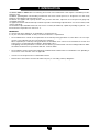
“Should overheating occur or the gas supply fail to shut off, do not turn
off or disconnect the electrical supply to the pump. Instead, shut off the
gas supply at a location external to the appliance”
Do not use this boiler if any part has been under water. Immediately call a
qualied service technician to inspect the boiler and to replace any part of
the control system and any gas control which has been under water.
WARNING: If the information in this manual is not followed exactly, a re or explosion may result causing pro-
perty damage, personal injury or loss of life.
— Do not store or use gasoline or other ammable vapors and liquids in the vicinity of this or any other
appliance.
— WHAT TO DO IF YOU SMELL GAS
• Do not try to light any appliance.
• Do not touch any electrical switch; do not use any phone in your building.
• Immediately call your gas supplier from a neighbor’s phone. Follow the gas supplier’s instructions.
• If you cannot reach your gas supplier, call the re department.
— Installation and service must be performed by a qualied installer, service agency or the gas supplier.

3
925.188.3 - GB
INSTRUCTIONS PERTAINING TO THE INSTALLER
The Luna 3 310 Fi - 1.310 Fi boilers are wall hung, fan assisted room-sealed boilers. Heat output is controlled by a modu-
lating gas valve.
The boilers, providing both central heating and domestic hot water at mains pressure, is designed for use with a fully
pumped, sealed and pressurised heating system.
The boilers are supplied with a pump, diverter valve, pressure relief valve, expansion vessel and pressure gauge fully
assembled and tested.
As supplied, the boilers will automatically modulate to provide central heating outputs between 10.4 and 31.0 kW (35 486
and 105 776 Btu/h).
The maximum output available for domestic hot water is 31.0 kW (105 776 Btu/h), capable of providing 2.8 gal/min. - 12.7
litres/min with a temperature rise of 63°F/35 °C.
IMPORTANT
It is the law that all gas appliances are installed by a competent person.
It is in your own interest and that of safety to ensure that the law is complied with.
• The installation must conform to the requirements of the authority having jurisdiction or, in the absence of such requi-
rements, to the National Fuel Gas Code, ANSI Z223.1/NFPA 54
Where required by the authority having jurisdiction, the installation must conform to the Standard for Controls and
Safety Devices for Automatically Fired Boilers, ANSI/ASME CSD-1.*
Safe lighting and other performance criteria were met with the gas manifold and control assembly provided on boiler
when boiler underwent tests specied in ANSI Z21.13-latest edition.
• The installation should conform with CGA B149.1 INSTALLATION CODE and/or local installation Code, plumbing or
waste water codes and other codes as applicable.
• Clearances from and protection of combustible material.
• Manufacturer’s instructions must NOT be taken in anyway as over-riding statutory obligations.
1. INTRODUCTION

4
925.188.3 - GB
INSTRUCTIONS PERTAINING TO THE INSTALLER
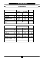
2. TECHNICAL DATA
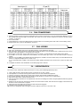
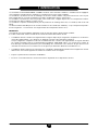
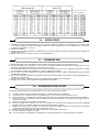
2.1 PERFORMANCE
Central Heating MAX MIN
0÷2000 Ft 2000÷4500 Ft
0÷610 m 610÷1370 m
Heat Input Btu/h 126 249 120 107 45 040
(Gross) kW 37 35.2 13.2
Heat Output (modulating) Btu/h 105 776 100 658 35 486
kW 31 29.5 10.4
Burner Pressure Setting p.s.i. 0.203 0.186 0.0261
natural gas (A) mbar 14.0 12.8 1.8
Gas Rate ft
3
/h 124.2 118.2 44.5
natural gas (A) m
3
/h 3.52 3.35 1.26
Burner Pressure Setting p.s.i. 0.3541 0.3338 0.0479
LP gas (E) mbar 24.4 23.0 3.3
Gas Rate ft
3
/h 49.0 46.6 17.29
LP gas (E) m
3
/h 1.39 1.32 0.49
CH Water Temp. °F 185
(Approx.) °C 85
Domestic Hot Water MAX MIN
0÷2000 Ft 2000÷4500 Ft
0÷610 m 610÷1370 m
Heat Input Btu/h 126 249 120 107 45 040
(Gross) kW 37 35.2 13.2
Heat Output (modulating) Btu/h 105 776 100 658 35 486
kW 31 29.5 10.4
Burner Pressure Setting p.s.i. 0.203 0.186 0.0261
natural gas (A) mbar 14.0 12.8 1.8
Gas Rate ft
3
/h 124.2 118.2 44.5
natural gas (A) m
3
/h 3.52 3.35 1.26
Burner Pressure Setting p.s.i. 0.3541 0.3338 0.0479
LP gas (E) mbar 24.4 23.0 3.3
Gas Rate ft
3
/h 49.0 46.6 17.29
LP gas (E) m
3
/h 1.39 1.32 0.49
Flow Rate
(Can) G.P.M.
2.4
at 72°F/40°C Rise
(USA) G.P.M.
2.9
l/m 11.1
Outlet Water Temp. °F 149
(Approx.) °C 65

5
925.188.3 - GB
INSTRUCTIONS PERTAINING TO THE INSTALLER
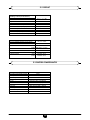
2.2 SYSTEM
Central Heating (Sealed System)
Max System Pressure 30 p.s.i. / 2.11 bar
Min System Pressure 7.25 p.s.i. / 0.5 bar
Max System temperature 185°F / 85°C
Pressure Relief Valve Setting 30 p.s.i. / 2.11 bar
Expansion Vessel Size 2.2 Gal / 10 l
(pre-charge press.) at 11.6 p.s.i. / 0.8 bar
Flow Connection 3/4” / 22.2 mm
Return Connection 3/4” / 22.2 mm
Relief Valve Connection 3/4” / 22.2 mm
Recommended System Pressure (cold) 21.7 p.s.i. / 1.5 bar
Domestic Hot Water
Max Mains Inlet Pressure 116 p.s.i. / 8 bar
Min Mains Water Pressure 2.9 p.s.i. / 0.2 bar
Min DHW Flow Rate (Can) 0.55 GPM / 2.5 l/min
(USA) 0.66 GPM / 2.5 l/min
Mains Inlet Connection 1/2” / 15.9 mm
DHW Outlet Connection 1/2” / 15.9 mm
Max DHW Temperature 149°F / 65°C
DHW Water Content (Can) 0.05 Gal / 0.23 l
(USA) 0.06 Gal / 0.23 l
2.3 COMPONENTS
Burner (15 blade) Stainless Steel
Main Heat exchanger Copper
DHW Heat exchanger Stainless Steel
Injectors natural gas (A) 1.28 mm
Injectors LPG gas (E) 0.90 mm
Pump Grundfos UPS 15-62/BX AO
Flue - Outer Duct Epoxy coated
Flue - Inner Duct Aluminium
Fan MVL RLG 97/3400 - 3030LH
Gas Valve SIT 845 SIGMA
Air Pressure Switch HUBA
Diverter Valve Baxi

6
925.188.3 - GB
INSTRUCTIONS PERTAINING TO THE INSTALLER
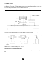
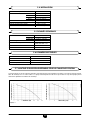
2.4 INSTALLATION
Minimum Clearances for Servicing
Top 8.66 in / 220 mm
Bottom 9.84 in / 250 mm
Sides 1.77 in / 45 mm
Front 17.71 in / 450 mm
Flue Terminal Size Concentric System 3.93 in / 100 mm
Flue Terminal Size 2-Pipe Flue System 3.14 in / 80 mm
Flue Terminal Protruding 4.52 in / 115 mm
Lift Weight 88 lb / 40 kg
Dimensions Height 30.04 in / 763 mm
Width 17.71 in / 450 mm
Depth 13.78 in / 350 mm
Gas Connection 3/4”
Primary Water Content (Can) 0.33 Gal / 1.5 l
(USA) 0.40 Gal / 1.5 l
Air Duct Diameter 3.93 in / 100 mm
Flue Duct Diameter 2.36 in / 60 mm
Supply 120 V 60 Hz
Power Consumption 563 Btu /h - 165 W
Internal Fuse 3.15 A
Electrode Spark Gap 2.5 to 3.5 mm
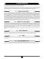
2.5 GENERAL
2.6 ELECTRICAL
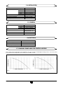
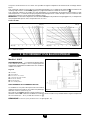
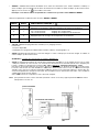
2.7 AVAILABLE PUMP HEAD FOR CENTRAL HEATING
This is a high static head pump t for installation on any type of single or double-pipe heating systems. The air vent valve
incorporated in the pump allows quick venting of the heating system.
Graph 1
WATER FLOW RATE
(l/h)
PUMP HEAD
(mH
2
O)
0711_2301
WATER FLOW RATE (gal/h)
PUMP HEAD
(ft w.c.)

7
925.188.3 - GB
INSTRUCTIONS PERTAINING TO THE INSTALLER
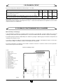
2.8 SYSTEM VOLUME
Based on 30 p.s.i. / 2.11 bar safety valve setting
Vessel charge and initial system pressure bar 0.5 1.0 1.5
psi 7.25 14.5 21.7
Total water content of system using 2.2 gal / 10 l Litres 120 91 64
capacity expansion vessel (Can)
gal 26.4 20 14
supplied with appliance (USA)
gal 31.7 24 16.9
For systems having a larger capacity MULTIPLY the TOTAL system capacity in litres (gallons) by 0.0833 0.109 0.156
the factor to obtain the TOTAL MINIMUM expansion vessel capacity required in litres (gallons)
Note: When the boiler is operating at maximum operating temperature, providing heating with all radiators operating, the
pressure gauge should not indicate more than 25.5 p.s.i. / 1.8 bar. If the reading exceeds this gure an additional expan-
sion vessel is required.
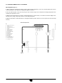
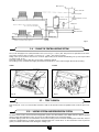
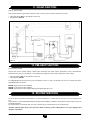
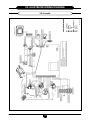
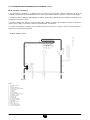
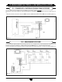
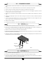
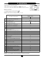
2.9 BOILER SCHEMATIC
Central Heating Mode (Fig. 1)
1. With a demand for heating, the pump circulates water through the primary circuit. At a pre-determined ow rate the
central heating ow switch operates, initiating the ignition sequence.
2. The main burner ignites at low rate, then the gas valve controls the gas rate to maintain the heating temperature mea-
sured by the temperature sensor.
3. When the ow temperature exceeds the setting temperature, a 3 minute delay occurs before the burner relights auto-
matically (anti-cycling). The pump continues to run during this period.
4. When the demand is satised the burner is extinguished and the pump continues to run for a period of 3 minutes (Pump
Overrun).
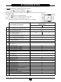
Central Heating Circuit
Key
1 Primary Heat Exchanger
2 Burner
3 Ignition Electrode
4 Flame Sensing Electrode
5 Gas Valve
6 Pump
7 Automatic Air Vent
8 Expansion Vessel
9 Plate Heat Exchanger
10 Flow Sensor with Filter
11 Boiler Drain Point
12 Pressure Relief Valve
13 Heating Return
14 Cold Water Inlet On/Off Valve and Filter
15 Gas Inlet
16 Domestic Hot Water Outlet
17 Heating Flow
18 Automatic By-Pass
19 Water Pressure Switch
20 Manometer
21 Domestic Hot Water Temperature Sensor
22 Three Way Valve
23 Three Way Valve Motor
24 Safety Thermostat
25 Central Heating Temperature Sensor
Fig. 1
0610_1201 / CG_1857

8
925.188.3 - GB
INSTRUCTIONS PERTAINING TO THE INSTALLER
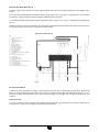
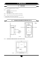
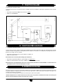
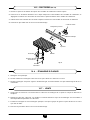
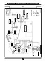
2.9.1 BOILER SCHEMATIC FOR 1.310 Fi MODEL
Operating Mode (Fig. 1.1)
1. With a demand for heating, the pump circulates water through the primary circuit. At a pre-determined ow rate the
central heating ow switch operates, initiating the ignition sequence.
2.
The main burner ignites at low rate, then the gas valve controls the gas rate to maintain the heating temperature mea-
sured by the temperature sensor.
3. When the ow temperature exceeds the setting temperature, a 3 minute delay occurs before the burner relights auto-
matically (anti-cycling). The pump continues to run during this period.
4. When the demand is satised the burner is extinguished and the pump continues to run for a period of 3 minutes (Pump
Overrun).
Boiler Primary Circuit
Fig. 1.1
0610_1702 / CG_1859
Key
1 Primary Heat Exchanger
2 Burner
3 Ignition Electrode
4 Flame Sensing Electrode
5 Gas Valve
6 Pump
7 Automatic Air Vent
8 Expansion Vessel
9 Boiler Drain Point
10 Pressure Relief Valve
11 Boiler Return
12 Gas Inlet
14 Automatic By-Pass
15 Three Way Valve
16 Manometer
17 Boiler Flow
18 Three Way Valve
19 Three Way Valve Motor
20 Safety Thermostat
21 Temperature Sensor

9
925.188.3 - GB
INSTRUCTIONS PERTAINING TO THE INSTALLER
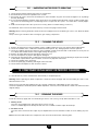
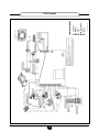
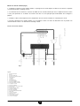
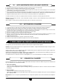
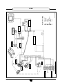
Domestic Hot Water Mode (Fig. 2)
1. Priority is given to the domestic hot water supply. A demand at a tap or shower will override any central heating requi-
rement.
2. The ow of water will operate the DHW ow switch which requests the 3 way valve to change position. This will allow
the pump to circulate the primary water through the DHW plate heat exchanger.
3. The burner will light automatically and the temperature of the domestic hot water is controlled by the temperature
sensor.
4. When the domestic hot water demand ceases the burner will extinguish and the diverter valve will remain in the dome-
stic hot water mode, unless there is a demand for central heating.
Domestic Hot Water Circuit
Fig. 2
0610_1203 / CG_1858
Key
1 Primary Heat Exchanger
2 Burner
3 Ignition Electrode
4 Flame Sensing Electrode
5 Gas Valve
6 Pump
7 Automatic Air Vent
8 Expansion Vessel
9 Plate Heat Exchanger
10 Flow Sensor with Filter
11 Boiler Drain Point
12 Pressure Relief Valve
13 Heating Return
14 Cold Water Inlet On/Off Valve and Filter
15 Gas Inlet
16 Domestic Hot Water Outlet
17 Heating Flow
18 Automatic By-Pass
19 Water Pressure Switch
20 Manometer
21 Domestic Hot Water Temperature Sensor
22 Three Way Valve
23 Three Way Valve Motor
24 Safety Thermostat
25 Central Heating Temperature Sensor
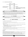
Frost Protection Mode
1. Boilers electronic management includes a “frost protection” function in the central heating system which operates the
burner to reach a heating ow temperature of 30°C when the system heating ow temperature drops below 5 °C. This
function is enabled when the boiler is connected to electrical supply, the gas supply is on and the system pressure is as
required.
Pump Protection
1. In the event that no heat is required, the pump will automatically start up and operate for one minute during the fol-
lowing 24 hours. This function is operative when the boiler is powered.

10
925.188.3 - GB
INSTRUCTIONS PERTAINING TO THE INSTALLER
3. GENERAL BOILER INFORMATION
The boiler requires a gas rate of 128.1 ft
3
/h - 3.63m
3
/h.
The meter and supply pipes must be capable of delivering this quantity of gas in addition to the demand from any other
appliances in the house. The boiler requires at least a 3/4” gas supply pipe. The complete installation, including the meter,
must be tested for gas leak and purged.
3.1 GAS SUPPLY
WARNING :
If the heating is directly connected to a oor heating system, a safety overheating thermostat should be provided by the
installer.
3.4.1 CONCENTRIC SYSTEM
The ue assembly supplied for the boiler is 2.64 ft / 0.75 m in length + terminal.
For horizontal ues a minor deviation from the horizontal is allowable, provided it results in a downward slope towards
the terminal.
Additional ue components are available as follows:
3.28 ft / 1 m ue
90° bend
45° bend
Vertical ue terminal assembly. Refer to the separate installation instructions supplied with the assembly.
Notes: If an extra 90° bend is used, this reduces the maximum ue length by 3.28 ft / 1 m. Each 45° bend used reduces
the maximum ue length by 1.64 ft / 0.5 m.
Under no circumstances must the ue length (including allowances for extra bends) exceed 4 m / 13.12 ft.
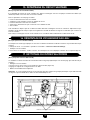
The boiler requires a 120V 60Hz power supply. Ensure the electrical supply is polarised.
The boiler must be grounded.
There must only be one common isolator, providing complete electrical isolation, for the boiler and any external con-
trols.
Using PVC insulated cable 18 AWG x3C 105 °C.
All wiring must be installed in accordance with requirements of National Electrical Code and any additional national, state,
or local code requirements having jurisdiction. All wiring must be N.E.C. Class 1. Boiler must be electrically grounded in
accordance with the National Electrical Code, ANSI/NFPA No. 70-latest edition.
In Canada, installation must conform to CSA C22.1 Canadian Electrical Code Part 1 and any local codes.
3.2.1 Install Room Thermostat
Install room thermostat on an inside wall. Never install where it will be inuenced by drafts, hot or cold water pipes, lighting
xtures, television, sun rays or near a replace.
3.2 ELECTRICAL SUPPLY
The boiler does not require any air vents in the room in which it is installed, or when installed in a cupboard or compart-
ment.
3.3 AIR SUPPLY
3.4 FLUE SYSTEM

11
925.188.3 - GB
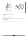
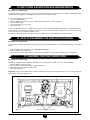
INSTRUCTIONS PERTAINING TO THE INSTALLER
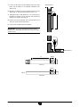
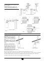
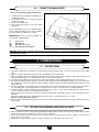
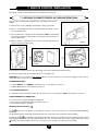
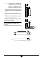
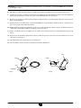
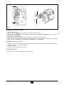
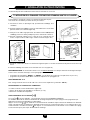
1. Locate the ue elbow on the adaptor at the top of the
boiler. Set the elbow to the required orientation (rear,
right or left).
2. Measure the distance from the outside wall face to the
elbow (Fig. 3). This dimension will be known as ‘X’.
3. Taking the air duct, mark dimension ‘X’ as shown (Fig. 4).
Measure the length of waste material, and transfer the
dimension to the ue duct (Fig. 4).
4. Remove the waste from both ducts. Ensure that the cut
ends are square and free from burrs.
5. Remove the ue elbow from the adaptor.
IMPORTANT: Check all measurements before cutting.
Clearance to combustible materials when using concentric
system is zero.
Wall Thickness
(X)
Wall Thickness
(X)
Fig. 3
Waste
(X)
Waste
Fig. 4
Air Duct
Flue Duct

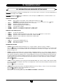
12
925.188.3 - GB
INSTRUCTIONS PERTAINING TO THE INSTALLER
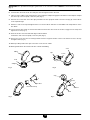
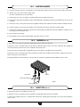
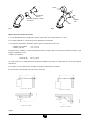
IMPORTANT: If the equivalent flue length is greater than 1.5 m / 4.92 ft the restrictor MUST be removed from the adaptor
(Fig. 5).
6. Insert the flue duct into the air duct and pass them through the hole in the wall.
7. Take one of the rubber seals and position it on the boiler flue adaptor. Engage the flue elbow on the adaptor and pull
the sleeve up so that it equally covers the joint (Fig. 5).
8. Remove the screws from one of the clips provided. Prise the clip apart and fit it over the seal (Fig. 6). Set the elbow
to the required angle.
9. Refit the screws to the clip and tighten them to secure the elbow. Take the second rubber seal and position it on the
flue elbow.
10. Locate the flue duct clamp on the flue outlet elbow. Draw the flue duct out of the air duct, engage it in the clamp and
tighten the screws (Fig. 7).
11. Draw the air duct out of the wall and align it with the elbow.
Position the seal so that it equally covers the joint (Fig. 8).
12. Remove the screws from the second clip provided. Prise the clip apart and fit it over the seal. Refit the screws to the clip
and tighten them (Fig. 8).
13. Where possible position the clips so that the screws are not visible.
14. Make good between the wall and air duct outside the building.
Fig. 5
Seal
Adaptor
Restrictor
Elbow
Fig. 6
Seal
Clip
Screw
Fig. 7
Flue Duct Clamp
Flue Duct
Air Duct
Seal
Clip
Screw
Fig. 8

13
925.188.3 - GB
INSTRUCTIONS PERTAINING TO THE INSTALLER
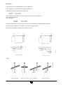
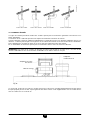
Flue Options
1. The Baxi boiler can be tted with ue systems as illustrated.
2. The standard ue is suitable only for horizontal applications.
3. Maximum permissible equivalent ue lengths are:
Concentric 4 m / 13.12 ft
Vertical 4 m / 13.12 ft
4. Any additional “in line” bends in the ue system must be taken into consideration.
Their equivalent lengths are:-
Concentric Pipes:
45° bend 0.5 m / 1.64 ft
90° bend 1.0 m / 0.82 ft
The elbow supplied with the standard horizontal ue is not included in any equivalent length calculations
5. The illustrations opposite show examples of maximum equivalent lengths.
6. Instructions for guidance and tting are included in each kit.
Fig. 9a
L max = 4 m / 13.12 ft
L max = 4 m / 13.12 ft
L max = 3 m / 9.84 ft
L max = 3 m / 9.84 ft
0512_2001
0503_0908/CG1641
L max = 4 m / 13.12 ft L max = 4 m / 13.12 ft L max = 2 m / 6.56 ft L max = 3 m / 9.84 ft

14
925.188.3 - GB
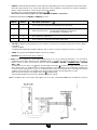
INSTRUCTIONS PERTAINING TO THE INSTALLER
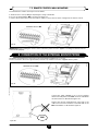
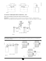
3.4.2 TWO PIPE SYSTEM
This type of ducting allows to disengage exhaust ue gases both outside the building and into single ue ducts.
Comburant air may be drawn in at a different site from where the ue terminal is located.
The splitting kit consists of a ue duct adaptor (100/80) and of an air duct adaptor; the latter may be placed either on the
left or on the right of the ue terminal according to installation requirements.
For the air duct adaptor t the screws and seals previously removed from the cap.
The restrictor must be removed in case you install separated ue and air duct terminals.
IMPORTANT: All parts of the exhaust ue duct must be at least 1 in / 25.4 mm from any combustible materials or zero
mm to combustibles if mylar sleeve is used.
The 90° bend allows to connect the boiler to ue-air ducting regardless of direction as it can be rotated by 360°. It can
moreover be used as a supplementary bend to be coupled with the duct or with a 45° bend.
Intake air duct adaptor
ue duct adaptor
clamp
Fig. 10
A 90° bend reduces the total duct length by 0.5 m / 1.64 ft.
A 45° bend reduces the total duct length by 0.25 m / 0.82 ft.
Separated horizontal flue terminals installation options
IMPORTANT: Ensure a minimum downward slope of 1 cm / 0.39 in toward the outside per each metre of duct length
In the event of installation of the condensate collection kit, the angle of the drain duct must be directed towards the
boiler.
Fig. 11
0504_1806/CG_1794

15
925.188.3 - GB
INSTRUCTIONS PERTAINING TO THE INSTALLER
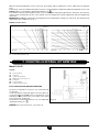
(L1 + L2) max = 25 m / 0.82 ft
L max = 8 m / 26.24 ft
The maximum length of the suction duct must
be 10 m / 32.80 ft.
If the ue duct exceeds 6 m / 19.68 ft, the
condensate collection kit (supplied as an
accessory) must be tted close to the boiler.
Fig. 12
Fig. 13
Fig. a Fig. b
Fig. c
3.93 in
100 mm
2.36 in
60 mm
2.36 in
60 mm
7.87 in
200 mm
min. 4.72 in / 120 mm
970109_1301
970109_1201
970109_1101
0610_1204
L max = 11 m / 36.08 ftL max = 12 m / 39.36 ft
Fig. 14
Separated vertical flue terminals installation options
Important: if tting a single exhaust
ue duct, ensure it is adequately insu-
lated (e.g.: with glass wool) wherever
the duct passes through building
walls.
For detailed instructions concerning
the installation of ttings refer to the
technical data accompanying the
ttings.
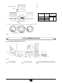
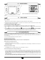
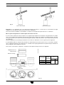
Split flue air control adjustment
The adjustment of this control is
required to optimise performance and
combustion parameters. The air suction
coupling which may be mounted on
the left or right of the ue duct can be
rotated to adjust excess air according
to the total length of the ue and intake
ducts for the combustion air.
Turn this control clockwise to decrease excess combustion air and anticlockwise to increase it.
To improve optimisation a combustion product analyser can be used to measure the CO
2
contents of the ue at maximum
heat output, gradually adjusting air to obtain the CO
2
reading in the table below, if the analysis shows a lower value.
To properly install this device, also refer to the technical data accompanying the tting.

16
925.188.3 - GB
INSTRUCTIONS PERTAINING TO THE INSTALLER
Fig. 15
0604/2301/CG1776
Flue duct adaptor
Seal
Air suction coupling
adjust
Index
Opening
CONTROL
POSITION
CO
2
%
(L1+L2) MAX
G20 G31
7,4 8,5
0 ÷ 2
2 ÷ 10
10 ÷ 25
1
2
3
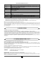
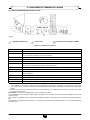
Fig. 16 IN COMPLIANCE WITH CGA B149
= AREA WHERE TERMINAL IS NOT PERMITTED
= AIR SUPPLY INLET= VENT TERMINAL
Fig. 16
3.5 FLUE TERMINAL LOCATION

17
925.188.3 - GB
INSTRUCTIONS PERTAINING TO THE INSTALLER
* a vent shall not terminate directly above a side-walk or paved driveway which is located between two single family
dwellings and serves both dwellings unless terminated 7ft above sidewalk.
** only permitted if veranda, porch, deck or balcony is fully open on a minimum of 2 sides beneath the oor.
Note: local Codes or Regulations may require different clearances.
The ue terminal must be exposed to the external air and the position must allow the free passage of air across it at all
times. In certain weather conditions the terminal may emit a plume of steam. Avoid positioning the terminal where this
may cause a nuisance.
If the terminal is tted less than 6.56 ft / 2 m above a surface to which people have access, the terminal must be protected
by a terminal guard.
Vent Termination Minimum Clearances
A = 12” clearances above grade, veranda, porch, deck or balcony
B = 12” clearances to window or door that may be opened
D = 18” vertical clearance to ventilated soft located above the terminal within a horizontal distance of 2
feet (60 cm) from the centre line of the terminal
E = 18” clearance to unventilated soft
F = 9” clearance to outside corner
G = 6” clearance to inside corner
H = 4 ft. (U.S.A.) not to be installed above a gas meter/regulator assembly within H horizontally from the centre
line of the regulator
I = 3 ft. (U.S.A.) clearance to service regulator vent outlet
6 ft. (Canada)
J = 9” (U.S.A.) clearance to non-mechanical air supply inlet to building or the combustion air inlet to any other
appliance
K = 3 ft. (U.S.A.) clearance to a mechanical air supply inlet
6 ft. (Canada)
* L = 7 ft. clearance above paved side-walk or a paved driveway located on public property
**
M = 18” clearance under veranda, porch, deck or balcony
The boiler is not suitable for external installation.
The boiler must be installed on a at vertical wall which is capable of supporting the weight of the boiler.
The boiler may be installed in any room or internal space, although particular attention is drawn to the requirements of the
current electrical provisions with respect to the installation of the boiler in a room or internal space containing a bath or
shower. Where a room-sealed boiler is installed in a room containing a bath or shower, it must not be possible for a person
using the bath or shower to touch any electrical switch or boiler control utilising mains electricity.
The boiler may be installed in a cupboard or compartment, provided it is correctly designed and sufciently ventilated for
that purpose.
3.6 BOILER LOCATION
The boiler is designed for use in a sealed central heating system.
Refer to Technical Data, section 2.8, for details of the heating system volume.
The system should be designed to operate with ow temperatures of up to 185 °F / 85°C. When designing the system,
the pump head, expansion vessel size, mean radiator temperature, etc. must all be taken into account. Refer to the pump
performance table for guidelines.
The boiler is supplied with the following components built in:
Pressure relief valve - set to operate at 43 p.s.i. / 3 bar. The discharge pipe must be routed clear of the boiler to a drain,
in such a manner that it can be seen, but cannot cause injury to persons or property.
Manual operation of relief valve at least once a year.
WARNING: 1. Avoid contact with not water coming/out
2. Prevent water demage
Pressure gauge - to indicate the system pressure to be maintained.
Expansion vessel - with a capacity of 2.2 gal / 10 l and pre-charged to a pressure of 7.25 p.s.i. / 0.5 bar.
By-pass - The boiler incorporates an automatic by-pass. However, where all radiators are tted with thermostatic radiator
valves, an external by-pass must be tted.
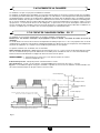
3.7 CENTRAL HEATING SYSTEM - FIG. 17

18
925.188.3 - GB
INSTRUCTIONS PERTAINING TO THE INSTALLER
Fig. 17
Make up vessel
3.28 ft / 1 metre min
Static head of system
Additional expansion vessel (if
required)
Filling point
DHW outlet
Mains water inlet
System
drain tap
By-pass could be a 0.86 in / 22 mm pipe controlled by a
valve or an uncontrolled radiator
Note
: A drain tap should be installed at the lowest point of the
heating circuit and beneath the appliance.
Heating
by-pass
(if required)
Heating retum
Heating flow
Boiler
Radiator
valve
Vanne
radiateur
Lockshield
valve
Automatic air vent
The system design pressure (cold) should be set to (7.25-14.5) p.s.i. / (0.5-1) bar. This pressure is equivalent to the maxi-
mum static head (see Fig. 17) in bar + 0.3 (14.5 p.s.i. = 1 bar = 10.2 metres of water).
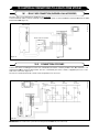
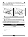
Filling of the system must be carried out in a manner approved by the local Water Undertaking. The system may be lled
as shown in Fig. 18-19.
Drain taps must be used to allow the system to be completely drained.
The heating system should be thoroughly ushed before the boiler is connected and again after the rst heating.
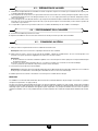
Fig. 18
Toxic chemicals, such as used for boiler treatment, shall not be introduced into the potable water used for space hea-
ting.
3.8 - FILLING THE CENTRAL HEATING SYSTEM
3.9 - TOXIC CHEMICAL
0603_1302/CG_1791
boiler lling tap
boiler drain point
Manometer
0603_1303/CG_1791
310 Fi 1.310 Fi
boiler lling tap
Fig. 19
The boiler, when used in connection with a refrigeration system, must be installed so the chilled medium is piped in parallel
with the boiler with appropriate valves to prevent the chilled medium from entering the boiler.
The boiler piping system of a hot water boiler connected to heating coils located in air handling units where they may be
exposed to refrigerated air circulation must be equipped with ow control valves or other automatic means to prevent
gravity circulation of the boiler water during the cooling cycle.
3.10 - HEATING SYSTEM AND REFRIGERATION SYSTEM

19
925.188.3 - GB
INSTRUCTIONS PERTAINING TO THE INSTALLER
1. The boiler is supplied in four boxes, as follows:
Box 1 Cased boiler
Water and gas valves plus washers
Water ttings.
Screws and wall plugs
Wall template
Box 2 90° ue bend with clamp (not required for vertical ue)
Box 3 2.64 ft / 0.75 m ue (for side and rear ue) with terminal
2. Unpack boiler and remove loose items packs.
3. Remove the two screws at the top of the front casing. Slide it up
4. INSTALLATION
4.1 - UNPACKING
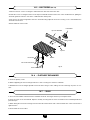
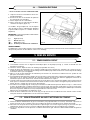
4.2 - CLEARANCES REQUIRED FOR SERVICING (FIG. 20)
1.77 in / 45 mm
1.77 in / 45 mm
8.66 in / 220 mm
9.84 in / 250 mm
17.71 in /
450 mm
30.04 in / 763 mm
Minimum
clearance of
17.71 in / 450
mm
from front of
boiler
Minimum
clearances
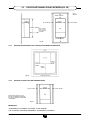
4.2.1. CLEARANCES REQUIRED FOR CLOSET INSTALLATION
1.77 in /
45 mm
1.77 in /
45 mm
1.57 in /
40 mm
Fig. 21
Fig. 20
13.58 in /
345 mm

20
925.188.3 - GB
INSTRUCTIONS PERTAINING TO THE INSTALLER
4.2.2. CLEARANCES FOR COMBUSTIBLES
1.77 in / 45 mm
1.77 in / 45 mm
17.71 in /
450 mm
Top and botton 0 in / 0 mm with a fire-
resistant material betwenn the boiler
and the combustibles material.
IMPORTANT:
• The boiler must not be installed on carpeting.
• Keepeng boiler area clear and free from flam-
mable vapors and liquid.
Fig. 22
1 Thoroughly ush out all the water pipework.
Note: Ensure that all the plastic caps are removed from the boiler connections.
2 Secure all the valves/ttings to the boiler- use the washers supplied, ensuring they are facing the rear wall. Fit the union
bends to the valves.
Note:
a. If soldering to the boiler union bends, ensure that the bends are not connected to the valves, otherwise the internal
seals may be damaged.
b. Ensure the 3/4” / 22.2 mm isolating valve with the lter is tted to the heating return connection.
c. Fit the pressure relief valve connection before the isolating valves.
3 Connect the system pipework to the boiler.
Note: Do not forget that the pressure relief valve discharge pipe must be routed clear of the boiler to a drain in such a
manner that it may be seen, but cannot cause injury to persons or property.
4 Ensure that all the valves are closed (spindle ats at right angles to valve) and do not turn on the water or gas supplies
at this stage.
IMPORTANT
The boiler and its individual shutoff valve must be disconnected from the gas supply piping system during any pressure testing
of that system at test pressures in excess of 1/2 psig (3.5 kPa).
The boiler must be isolated from the gas supply piping system by closing its individual manual shutoff valve during any
pressure testing of the gas supply piping system at test pressures equal to or less than 1/2 psig (3.5 kPa).
The boiler shall be installed such that the gas ignition system components are protected from water (dripping, spraying, rain,
etc.) during appliance operation and service (circulator replacement, condensate trap, control replacement, etc.)
1 Decide upon the position of the boiler taking into account the clearances required for servicing and the ue terminal
position.
2 Tape the template to the wall (ensure it is level and the right way up) and mark the position of the holes for the boiler
mounting bracket and bottom xings. If rear exit ue is used, mark the position of the hole for the ue.
3 If side exit ue is to be used, continue the horizontal centre line of the ue across the wall to the side wall, then along
the side wall (ensure the lines are horizontal). This will give the position of the centre of the hole for the ue.
4 Cut the 4.33 in / 110 mm diameter hole in the wall for the concentric ue.
4.3 - PREPARE THE WALL
1 Lift the boiler and locate it on the wall.
2 Adjust the position of the boiler, as necessary. Fit the screws to secure the boiler in position.
4.4 - FIT THE BOILER
4.5 - CONNECT THE PIPEWORK
La page est en cours de chargement...
La page est en cours de chargement...
La page est en cours de chargement...
La page est en cours de chargement...
La page est en cours de chargement...
La page est en cours de chargement...
La page est en cours de chargement...
La page est en cours de chargement...
La page est en cours de chargement...
La page est en cours de chargement...
La page est en cours de chargement...
La page est en cours de chargement...
La page est en cours de chargement...
La page est en cours de chargement...
La page est en cours de chargement...
La page est en cours de chargement...
La page est en cours de chargement...
La page est en cours de chargement...
La page est en cours de chargement...
La page est en cours de chargement...
La page est en cours de chargement...
La page est en cours de chargement...
La page est en cours de chargement...
La page est en cours de chargement...
La page est en cours de chargement...
La page est en cours de chargement...
La page est en cours de chargement...
La page est en cours de chargement...
La page est en cours de chargement...
La page est en cours de chargement...
La page est en cours de chargement...
La page est en cours de chargement...
La page est en cours de chargement...
La page est en cours de chargement...
La page est en cours de chargement...
La page est en cours de chargement...
La page est en cours de chargement...
La page est en cours de chargement...
La page est en cours de chargement...
La page est en cours de chargement...
La page est en cours de chargement...
La page est en cours de chargement...
La page est en cours de chargement...
La page est en cours de chargement...
La page est en cours de chargement...
La page est en cours de chargement...
La page est en cours de chargement...
La page est en cours de chargement...
La page est en cours de chargement...
La page est en cours de chargement...
La page est en cours de chargement...
La page est en cours de chargement...
La page est en cours de chargement...
La page est en cours de chargement...
La page est en cours de chargement...
La page est en cours de chargement...
La page est en cours de chargement...
La page est en cours de chargement...
La page est en cours de chargement...
La page est en cours de chargement...
-
 1
1
-
 2
2
-
 3
3
-
 4
4
-
 5
5
-
 6
6
-
 7
7
-
 8
8
-
 9
9
-
 10
10
-
 11
11
-
 12
12
-
 13
13
-
 14
14
-
 15
15
-
 16
16
-
 17
17
-
 18
18
-
 19
19
-
 20
20
-
 21
21
-
 22
22
-
 23
23
-
 24
24
-
 25
25
-
 26
26
-
 27
27
-
 28
28
-
 29
29
-
 30
30
-
 31
31
-
 32
32
-
 33
33
-
 34
34
-
 35
35
-
 36
36
-
 37
37
-
 38
38
-
 39
39
-
 40
40
-
 41
41
-
 42
42
-
 43
43
-
 44
44
-
 45
45
-
 46
46
-
 47
47
-
 48
48
-
 49
49
-
 50
50
-
 51
51
-
 52
52
-
 53
53
-
 54
54
-
 55
55
-
 56
56
-
 57
57
-
 58
58
-
 59
59
-
 60
60
-
 61
61
-
 62
62
-
 63
63
-
 64
64
-
 65
65
-
 66
66
-
 67
67
-
 68
68
-
 69
69
-
 70
70
-
 71
71
-
 72
72
-
 73
73
-
 74
74
-
 75
75
-
 76
76
-
 77
77
-
 78
78
-
 79
79
-
 80
80


Baxi Luna 3 Comfort 310 Fi Installation And Servicing Instructions
- Catégorie
- Chauffe-eau
- Taper
- Installation And Servicing Instructions
- Ce manuel convient également à
dans d''autres langues
- English: Baxi Luna 3 Comfort 310 Fi
Documents connexes
Autres documents
-
Riello Caldariello Condens 25 KIS Manuel utilisateur
-
 DEVILLE DMV 27-60 V Le manuel du propriétaire
-
Dunkirk DCC/DCB High Efficiency Wall Mounted Modulating Condensing Boiler Installation & Operation Manual
-
ACV HeatMaster C, TC Technical Manual
-
-
Rinnai E110SRN Guide d'installation
-
-
White Rodgers 1311 Manuel utilisateur
-
Ferroli D F24 Manuel utilisateur
-
Mark GSX 55 Technical Manual
