Hatco HBG, HBGB Series Le manuel du propriétaire
- Taper
- Le manuel du propriétaire

P/N 07.04.431.00 © 2020 Hatco Corporation
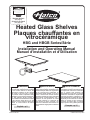
Heated Glass Shelves
Plaques chauffantes en
vitrocéramique
HBG and HBGB Series/Série
Installation and Operating Manual
Manuel d’installation et d’utilisation
hatcocorp.com
Register Online!
(see page 2)
S’inscrire en ligne!
(voir page 15)
Do not operate this equipment unless you
have read and understood the contents
of this manual! Failure to follow the
instructions contained in this manual
may result in serious injury or death.
This manual contains important safety
information concerning the maintenance,
use, and operation of this product. If
you’re unable to understand the contents
of this manual, please bring it to the
attention of your supervisor. Keep this
manual in a safe location for future
reference.
English = p 2
WARNING
No opere este equipo al menos que haya
leído y comprendido el contenido de este
manual! Cualquier falla en el seguimiento
de las instrucciones contenidas en
este manual puede resultar en un serio
lesión o muerte. Este manual contiene
importante información sobre seguridad
concerniente al mantenimiento, uso y
operación de este producto. Si usted
no puede entender el contenido de
este manual por favor pregunte a su
supervisor. Almacenar este manual en
una localización segura para la referencia
futura.
ADVERTENCIA
Ne pas utiliser cet équipement sans avoir
lu et compris le contenu de ce manuel ! Le
non-respect des instructions contenues
dans ce manuel peut entraîner de
graves blessures ou la mort. Ce manuel
contient des informations importantes
concernant l’entretien, l’utilisation et le
fonctionnement de ce produit. Si vous ne
comprenez pas le contenu de ce manuel,
veuillez le signaler à votre supérieur.
Conservez ce manuel dans un endroit
sûr pour pouvoir vous y référer plus tard.
Français = p 15
AVERTISSEMENT

2
Form No. HBGM-0120
English
CONTENTS
INTRODUCTION
Hatco Heated Glass Shelves are designed to hold food hot
safely while blending into the surrounding décor. They will keep
food at proper serving temperatures without affecting quality.
These units feature a thermostatically-controlled heated glass
base that extends the food holding times.
Heated Glass Shelves are a product of extensive research and
field testing. The materials used were selected for maximum
durability, attractive appearance, and optimum performance.
Every unit is inspected and tested thoroughly prior to shipment.
This manual provides the installation, safety, and operating
instructions for Heated Glass Shelves. Hatco recommends all
installation, operating, and safety instructions appearing in this
manual be read prior to installation or operation of a unit.
Safety information that appears in this manual is identified by
the following signal word panels:
WARNING
WARNING indicates a hazardous situation which, if not
avoided, could result in death or serious injury.
CAUTION
CAUTION indicates a hazardous situation which, if not
avoided, could result in minor or moderate injury.
NOTICE
NOTICE is used to address practices not related to
personal injury.
Important Owner Information ..............................................2
Introduction ...........................................................................2
Important Safety Information ..............................................3
Model Description ................................................................4
Model Designation ...............................................................4
Specifications .......................................................................5
Plug Configurations .............................................................5
Electrical Rating Chart .........................................................5
Dimensions .......................................................................... 6
Installation .............................................................................7
General ................................................................................ 7
HBG Models ........................................................................7
HBGB Models ......................................................................7
HBGB Countertop Cutout Chart .......................................... 8
Operation ...............................................................................9
General ................................................................................ 9
Maintenance ........................................................................10
General .............................................................................. 10
Daily Cleaning ...................................................................10
Cleaning Sugary/Sticky Spills ............................................10
Cleaning Burned-On Residue ...........................................10
Cleaning Metal Marks and Scratches ...............................10
Troubleshooting Guide ...................................................... 11
Options and Accessories .................................................. 11
International Limited Warranty .........................................14
Service Information ............................................................ 14
IMPORTANT OWNER INFORMATION
Record the model number, serial number (specification label
located on the bottom of the unit), voltage, and purchase date
of the unit in the spaces below. Please have this information
available when calling Hatco for service assistance.
Model No. ________________________________________
Serial No. _________________________________________
Voltage ___________________________________________
Date of Purchase ___________________________________
Register your unit!
Completing online warranty registration will prevent delay in
obtaining warranty coverage. Access the Hatco website at
www.hatcocorp.com, select the Support pull-down menu,
and click on “Warranty”.
Business
Hours: 7:00 to 5:00 Monday–Friday,
Central Time (CT)
(Summer Hours: June to September—
7:00 to 5:00 Monday–Thursday
7:00 to 4:00 Friday)
Telephone: 800-558-0607; 414-671-6350
E-mail: [email protected]
24 Hour 7 Day Parts and Service
Assistance available in the United States
and Canada by calling 800-558-0607.
Additional information can be found by visiting our web site at
www.hatcocorp.com.

Form No. HBGM-0120
3
English
IMPORTANT SAFETY INFORMATION
WARNING
ELECTRIC SHOCK HAZARD:
• Plug unit into a properly grounded electrical receptacle
of the correct voltage, size, and plug configuration. If
plug and receptacle do not match, contact a qualified
electrician to determine and install proper voltage and
size electrical receptacle.
• Turn OFF power switch, unplug power cord, and
allow unit to cool before performing any cleaning,
adjustments, or maintenance.
• DO NOT submerge or saturate with water. Unit is not
waterproof. Do not operate if unit has been submerged
or saturated with water.
• This unit is not “jet-proof” construction. Do not use jet-
clean spray to clean this unit.
• Unit is not weatherproof. Locate unit indoors where the
ambient air temperature is a minimum of 70°F (21°C).
• Do not pull unit by power cord.
• Discontinue use if power cord is frayed or worn.
• Do not attempt to repair or replace a damaged
power cord. The cord must be replaced by Hatco, an
Authorized Hatco Service Agent, or a person with
similar qualifications.
• Use only Genuine Hatco Replacement Parts when
service is required. Failure to use Genuine Hatco
Replacement Parts will void all warranties and may
subject operators of the equipment to hazardous
electrical voltage, resulting in electrical shock or burn.
Genuine Hatco Replacement Parts are specified to
operate safely in the environments in which they are
used. Some aftermarket or generic replacement parts
do not have the characteristics that will allow them to
operate safely in Hatco equipment.
FIRE HAZARD: Locate unit a minimum of 1″ (25 mm) from
combustible walls and materials. If safe distances are not
maintained, combustion or discoloration could occur.
Make sure food product has been heated to the proper
food-safe temperature before placing on the unit. Failure
to heat food product properly may result in serious health
risks. This unit is for holding preheated food product only.
This unit has no “user-serviceable” parts. If service is
required on this unit, contact an Authorized Hatco Service
Agent or contact the Hatco Service Department.
Make sure all operators have been instructed on the safe
and proper use of the unit.
This unit is not intended for use by children or persons
with reduced physical, sensory, or mental capabilities.
Ensure proper supervision of children and keep them away
from the unit.
CAUTION
BURN HAZARD: Some exterior surfaces on unit will get
hot. Use caution when touching these areas.
Locate unit at the proper counter height in an area that is
convenient for use. The location should be level to prevent
the unit or its contents from falling accidentally and strong
enough to support the weight of the unit and contents.
Do not operate built-in models without the control
box mounted properly as described in the installation
instructions.
The National Sanitation Foundation (NSF) requires that
units over 36″ (914 mm) in width or weighing more than
80 lbs. (36 kg) either be sealed to or raised above the
installation surface. If unit cannot be sealed at the point
of use, 4″ (102 mm) legs are included to allow for proper
cleaning access below unit.
Pitting or indentation in the glass surface may occur from
sugary spills. If pitting or indentation occurs, the glass
surface must be replaced. To prevent further damage
and possible injury from broken glass, stop using unit
immediately and contact an Authorized Hatco Service
Agent.
NOTICE
Damage to any countertop material caused by heat
generated from Hatco equipment is not covered under
the Hatco warranty. Contact the manufacturer of the
countertop material for application information.
Do not modify wiring or cut thermostat capillary on
control box to increase remote mounting distance. Cutting
thermostat capillary will cause unit to overheat and may
damage unit as well as surrounding countertop.
Do not turn on unit until it has been cleaned thoroughly.
Ceramic glass surface must be clear of debris to prevent
burn-on.
Do not slide pans across glass surface, use rough-
bottomed pans, or drop anything on glass surface.
Scratching or breakage may occur. Damage to glass
surface or breakage of glass caused by misuse is not
covered under warranty.
Use only wipes, pads, and cleaners designed specifically
for cleaning ceramic glass surfaces. Using other wipes,
pads, or cleaners may damage ceramic glass surface.
Do not install remote mounted control box in an area
subject to temperatures above 85°F (29°C). Excessive
temperatures will cause control(s) to overheat,
malfunction, and fail.
Read the following important safety information before using this equipment to avoid serious
injury or death and to avoid damage to equipment or property.

4
Form No. HBGM-0120
English
MODEL DESCRIPTION
MODEL DESIGNATION
All Models
All Hatco Heated Glass Shelves are ideal for pass through
areas, buffet lines, and as hors d’oeuvre displays. National
Sanitation Foundation (NSF) approval allows the placement
of food product directly on the glass surface, if desired.
Standard equipment includes an illuminated Power I/O (on/
off) switch, a thermostatically-controlled heated ceramic glass
top, and a painted steel base. The Heated Glass Shelves
have a temperature range of 100° to 200°F (38° to 93°C).
Heated Glass Shelves come standard with black glass and are
available with white glass as a factory installed option.
NOTE: The specification label is located on the bottom of the
unit. See label for serial number and verification of unit
electrical information.
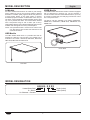
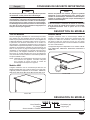
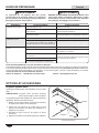
HBG Models
The HBG Heated Glass shelf is a portable shelf with an
available in six models: HBG-2418, HBG-3018, HBG-3618,
HBG-4818, HBG-6018 and HBG-7218.
Model HBG
HBGB Models
The HBGB Heated Glass shelf is a built-in unit that is equipped
with an attached trim mounting ring. The unit includes a
box to the power source.
The built-in units are available in six models: HBGB-2418,
HBGB-3018, HBGB-3618, HBGB-4818, HBGB-6018 and
HBGB-7218.
Model HBGB
H B G B - X X X X
Heated Glass Shelf
B = Built-In
No Character = Portable
Width (inches)
Depth (inches)

Form No. HBGM-0120
5
English
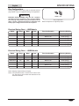
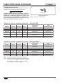
Model Voltage Watts Amps Plug Configuration Shipping Weight
HBG-2418 120 425 3.5
NEMA 5-15P 29 lbs. (13 kg)
HBG-3018 120 525 4.4
NEMA 5-15P 33 lbs. (15 kg)
HBG-3618 120 630 5.3
NEMA 5-15P 36 lbs. (16 kg)
HBG-4818 120 850 7.1
NEMA 5-15P 42 lbs. (19 kg)
HBG-6018 120 1050 8.8
NEMA 5-15P 60 lbs. (27 kg)
HBG-7218 120 1260 10.5
NEMA 5-15P 68 lbs. (31 kg)
SPECIFICATIONS
Plug Configurations
Units are supplied from the factory with an electrical cord and
plug installed. Plugs are supplied according to the application.
WARNING
ELECTRIC SHOCK HAZARD: Plug unit into a properly
grounded electrical receptacle of the correct voltage,
size, and plug configuration. If plug and receptacle do not
match, contact a qualified electrician to determine and
install proper voltage and size electrical receptacle.
NEMA 5-15P
Plug Configurations
NOTE: Receptacle not supplied by Hatco.
NOTE: Shipping weight includes packaging.
NOTE: The specification label is located on the bottom of the
unit. See label for serial number and verification of unit
electrical information.
Electrical Rating Chart — HBG Models
Electrical Rating Chart — HBGB Models
Model Voltage Watts Amps Plug Configuration Shipping Weight
HBGB-2418 120 425 3.5
NEMA 5-15P 32 lbs. (15 kg)
HBGB-3018 120 525 4.4
NEMA 5-15P 37 lbs. (17 kg)
HBGB-3618 120 630 5.3
NEMA 5-15P 40 lbs. (18 kg)
HBGB-4818 120 850 7.1
NEMA 5-15P 50 lbs. (23 kg)
HBGB-6018 120 1050 8.8
NEMA 5-15P 63 lbs. (29 kg)
HBGB-7218 120 1260 10.5
NEMA 5-15P 74 lbs. (34 kg)

6
Form No. HBGM-0120
English
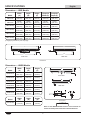
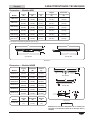
Model
Width
(A)
Depth
(B)
Height
(C)
Footprint
Width (D)
Footprint
Depth (E)
HBG-2418
24-3/8
(618 mm)
18-3/8
(466 mm)
2-1/2
(63 mm)
19-3/4
(503 mm)
13-3/4
(351 mm)
HBG-3018
30-3/8
(771 mm)
18-3/8
(466 mm)
2-1/2
(63 mm)
25-3/4
(656 mm)
13-3/4
(351 mm)
HBG-3618 †
36-3/8
(923 mm)
18-3/8
(466 mm)
6-1/8
(155 mm)
30-3/4
(780 mm)
12-3/4
(325 mm)
HBG-4818 †
48-3/8
(1228 mm)
18-3/8
(466 mm)
6-1/8
(155 mm)
42-3/4
(1086 mm)
12-3/4
(325 mm)
HBG-6018 †
60-3/8
(1533 mm)
18-3/8
(466 mm)
6-1/8
(155 mm)
54-3/4
(1391 mm)
12-3/4
(325 mm)
HBG-7218 †
72-3/8
(1838 mm)
18-3/8
(466 mm)
6-1/8
(155 mm)
66-3/4
(1696 mm)
12-3/4
(325 mm)
A
D E
B
C
Front View Side View
Dimensions
Dimensions — HBG Models
SPECIFICATIONS
Model
Width
(D)
Depth
(E)
Height
(F)
Remote Box
7
(178 mm)
2-1/2
(64 mm)
3
(76 mm)
Model
Width
(A)
Depth
(B)
Height
(C)
HBGB-2418
25-5/8
(651 mm)
19-5/8
(498 mm)
2-3/16
(55 mm)
HBGB-3018
31-5/8
(803 mm)
19-5/8
(498 mm)
2-3/16
(55 mm)
HBGB-3618
37-5/8
(955 mm)
19-5/8
(498 mm)
2-3/16
(55 mm)
HBGB-4818
49-5/8
(1260 mm)
19-5/8
(498 mm)
2-3/16
(55 mm)
HBGB-6018
61-5/8
(1565 mm)
19-5/8
(498 mm)
2-3/16
(55 mm)
HBGB-7218
73-5/8
(1870 mm)
19-5/8
(498 mm)
2-3/16
(55 mm)
A
B
D
E
C
F
Front View
Side View
Dimensions
Dimensions — HBGB Models
NOTICE
Refer to the INSTALLATION section of this manual for
actual countertop and remote box cutout dimensions.
†

Form No. HBGM-0120
7
English
General
Use the following procedures to install the HBG and HBGB
units.
WARNING
ELECTRIC SHOCK HAZARD: Unit is not weatherproof.
Locate unit indoors where the ambient air temperature is
a minimum of 70°F (21°C).
FIRE HAZARD: Locate unit a minimum of 1″ (25 mm) from
combustible walls and materials. If safe distances are not
maintained, combustion or discoloration could occur.
CAUTION
Locate unit at the proper counter height in an area that is
convenient for use. The location should be level to prevent
the unit or its contents from falling accidentally and strong
enough to support the weight of the unit and contents.
The National Sanitation Foundation (NSF) requires that
units over 36″ (914 mm) in width or weighing more than
80 lbs. (36 kg) either be sealed to or raised above the
installation surface. If this unit cannot be sealed at the
point of use, 102 mm (4″) legs are included to allow for
proper cleaning access below the unit.
NOTICE
Do not turn on unit until it has been cleaned thoroughly.
Ceramic glass surface must be clear of debris to prevent
burn-on.
Do not lay unit on the side with the control panel or damage
to the unit could occur.
HBG Models
1. Remove unit from box.
NOTE: To prevent delay in obtaining warranty coverage,
complete online warranty registration. See the
IMPORTANT OWNER INFORMATION section for
details.
2. Remove tape and protective packaging from all surfaces
of unit.
NOTE:If4″(102mm)legsarerequired,refertotheOPTIONS
AND ACCESSORIES section in this manual for
installationinstructions.4″(102mm)legsareincluded
withmodelsgreaterthan36″(1041mm)inwidth.
3. Place the unit in the desired location.
• Locate the unit in an area where the ambient air
temperature is constant and a minimum of 70°F
(21°C). Avoid areas that may be subject to active air
movements or currents (i.e., near exhaust fans/hoods,
air conditioning ducts, and exterior doors).
• Make sure the unit is at the proper counter height in an
area convenient for use.
• Make sure the countertop is level and strong enough to
support the weight of the unit and food product.
• Make sure all the feet on the bottom of the unit are
positioned securely on the countertop.
4. Install any accessories that came with the unit. Refer to the
OPTIONS AND ACCESSORIES section for details.
HBGB Models
CAUTION
Do not operate built-in models without the control box
mounted properly as described in the installation instructions.
NOTICE
Unit is designed and recommended for use in or on metallic
countertops. Damage to any countertop material caused
by heat generated from Hatco equipment is not covered
under the Hatco warranty. Verify with the manufacturer that
the material is suitable for prolonged temperatures up to
200°F (93°C).
Do not turn on unit until it has been cleaned thoroughly.
Ceramic glass surface must be clear of debris to prevent
burn-on.
1. Remove unit from box.
NOTE: To prevent delay in obtaining warranty coverage, complete
online warranty registration. See the IMPORTANT
OWNER INFORMATION section for details.
2. Remove tape and protective packaging from all surfaces
of unit.
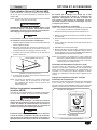
3. Prepare the countertop opening. Refer to the “HBGB
Countertop Cutout Chart” in this section for recommended
countertop cutout dimensions.
4. Apply a bead of NSF-approved sealant on the top edge
of the countertop cutout and the underside of the trim
mounting ring. The sealant must be rated for use at a
minimum temperature of 250°F (121°C).
5. Place the unit into the countertop opening.
6. Remove any excess sealant.
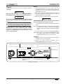
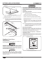
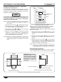
7. Locate the remote-mounted control box assembly in an area
that is convenient for operation. If desired or necessary, the
control box can be mounted in a semi-remote location.
• The control box can be panel, surface, or under counter
mounted. If recess mounting, the control box will require
• The distance the control box can be mounted from the
also available). Do not pull the conduit tight to increase
the mounting distance. The conduit should have some
slack after the control box is mounted.
Panel
Under Counter
Surface
7-1/4″
(184 mm)
7″
(178 mm)
3″
(76 mm)
3-1/4″
(83 mm)
Control Box Mounting Options
continued...
INSTALLATION

8
Form No. HBGM-0120
English
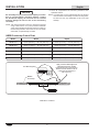
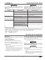
Model Width Depth
HBGB-2418 24-5/8625 mm) — 24-7/8632 mm) 18-5/8473 mm) — 18-7/8480 mm)
HBGB-3018 30-5/8778 mm) — 30-7/8784 mm) 18-5/8473 mm) — 18-7/8480 mm)
HBGB-3618 36-5/8930 mm) — 36-7/8936 mm) 18-5/8473 mm) — 18-7/8480 mm)
HBGB-4818 48-5/81235 mm) — 48-7/81241 mm) 18-5/8473 mm) — 18-7/8480 mm)
HBGB-6018 60-5/81540 mm) — 60-7/81546 mm) 18-5/8473 mm) — 18-7/8480 mm)
HBGB-7218 72-5/81845 mm) — 72-7/81851 mm) 18-5/8473 mm) — 18-7/8480 mm)
Trim Mounting Ring
Metallic
Countertop
Apply a bead of NSF-approved
sealant between the metallic
countertop and trim mounting ring.
Sealant must be rated for use at
a minimum temperature of
250°F (121°C).
HBGB Built-In Installation
INSTALLATION
HBGB Countertop Cutout Chart
NOTICE
Do not modify wiring or cut thermostat capillary on control
box to increase-remote mounting distance. Cutting
the thermostat capillary will cause the unit to overheat
and may damage the unit as well as the surrounding
countertop.
NOTE: The remote-mounted control box should be mounted
usingscrewswith a1/4″(6 mm)minimumdiameter
screw head inserted through the keyholes located on
the mounting brackets. The control box is to be readily
removable, not permanently mounted.
8. Once all components are secured, proceed to the
Operation section.
NOTE:A6′(1829mm)cordissuppliedwiththisunit.Excess
cord should be routed neatly so it does not hang down.
Do NOT cut cord, any modification to the cord voids
warranty.

Form No. HBGM-0120
9
English
General
Use the following procedure to turn on and operate a Heated
Glass Shelf.
WARNING
Read all safety messages in the IMPORTANT SAFETY
INFORMATION section before operating this equipment.
NOTICE
Do not turn on unit until it has been cleaned thoroughly.
Ceramic glass surface must be clear of debris to prevent
burn-on.
Use only wipes, pads, and cleaners designed specifically
for cleaning ceramic glass surfaces. Using other wipes,
pads, or cleaners may damage ceramic glass surface.
Do not slide pans across glass surface, use rough-
bottomed pans, or drop anything on glass surface.
Scratching or breakage may occur. Damage to glass
surface or breakage of glass caused by misuse is not
covered under warranty.
Startup
1. Using an appropriate cleaning wipe or a damp cloth, clean
the glass surface of the unit. Consistent daily cleaning will
keep cleanup easy as well as protect and preserve the
glass surface of the unit.
2. Plug unit into a properly grounded electrical receptacle of
the correct voltage, size, and plug configuration. See the
SPECIFICATIONS section for details.
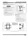
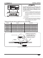
3. Move the Power I/O (on/off) switch to the I (on) position.
CAUTION
BURN HAZARD: Some exterior surfaces on the unit will get
hot. Use caution when touching these areas.
4. Turn the temperature control to the desired temperature
setting.
NOTE: Turning the temperature control clockwise will increase
the temperature setting. Turning the temperature
control counterclockwise will decrease the temperature
setting.
5. Allow the unit 30 minutes to reach operating temperature.
NOTE: Refer to the OPTIONS AND ACCESSORIES section
for installation and operation information for HBGB
unitsequippedwiththeflushmountcontrolbox.
Shutdown
1. Move the Power I/O (on/off) switch to the O (off) position
and allow the unit to cool completely.
2. Perform the “Daily Cleaning” procedure in the
MAINTENANCE section of this manual.
OPERATION
Power I/O (on/off)
Switch
Temperature Control
Standard Control Panel

10
Form No. HBGM-0120
English
General
Hatco Heated Glass Shelves are designed for maximum
durability and performance, with minimum maintenance.
WARNING
ELECTRIC SHOCK HAZARD:
• Turn OFF power switch, unplug power cord, and
allow unit to cool before performing any cleaning,
adjustments, or maintenance.
• DO NOT submerge or saturate with water. Unit is not
waterproof. Do not operate if unit has been submerged
or saturated with water.
• This unit is not “jet-proof” construction. Do not use
jet-clean spray to clean this unit.
This unit has no “user-serviceable” parts. If service
is required on this unit, contact an Authorized Hatco
Service Agent or contact the Hatco Service Department at
800-558-0607 or 414-671-6350.
NOTICE
Do not turn on unit until it has been cleaned thoroughly.
Ceramic glass surface must be clear of debris to prevent
burn-on.
Use only wipes, pads, and cleaners designed specifically
for cleaning ceramic glass surfaces. Using other wipes,
pads, or cleaners may damage ceramic glass surface.
Daily Cleaning
Consistent daily cleaning will keep cleanup easy as well as
protect and preserve the glass surface. Make sure to use only
wipes, pads, and cleaners designed specifically for cleaning
ceramic glass surfaces.
1. Before turning on the unit each day, clean the glass surface
using an appropriate cleaning wipe or a damp cloth.
2. At the end of each day:
a. Turn off the unit and allow to cool.
b. Clean the glass surface using an appropriate cleaning
wipe or damp cloth. If additional cleaning is necessary,
follow the “Cleaning Burned-On Residue” procedure in
this section.
Cleaning Sugary/Sticky Spills
To clean sugary/sticky spills, the unit should be warm while
cleaning for easier removal.
1. Turn off the unit and unplug power cord. CAUTION! Burn
Hazard—Heated glass will be hot. Use caution when
touching this area.
2. While unit is still warm, wear an oven mitt and remove the
bulk of the spill using paper towel.
3. Allow the unit to cool.
4. Follow the “Cleaning Burned-On Residue” procedure in
this section to remove the remainder of the spill.
5. Do not use the unit again until the spill has been cleaned
completely.
CAUTION
Pitting or indentation in the glass surface may occur from
sugary spills. If pitting or indentation occurs, the glass
surface must be replaced. To prevent further damage
and possible injury from broken glass, stop using unit
immediately and contact an Authorized Hatco Service
Agent.
Cleaning Burned-On Residue
To clean burned-on residue, the use of ceramic glass cleaner
may be necessary.
1. Turn off the unit, unplug power cord, and allow unit to cool.
2. Spread a few drops of ceramic glass cleaner onto the
residue area.
3. Using an appropriate cleaning wipe, rub the residue area
while applying pressure as needed.
4. If residue remains, repeat the steps above as needed.
5. After all residue has been removed, polish the entire glass
surface using the ceramic glass cleaner and paper towel.
Cleaning Metal Marks and Scratches
Metal marks and scratches from pans usually can be removed.
Be careful when placing pans onto the glass surface. To avoid
metal marks and scratches, do not slide pans across the glass
surface.
1. Turn off the unit, unplug power cord, and allow unit to cool.
2. Spread a few drops of ceramic glass cleaner onto the
marked area.
3. Using an appropriate cleaning wipe, rub the marked area
while applying pressure as needed.
4. If metal marks and scratches remain, repeat the steps
above as needed.
NOTE: Check the bottom of all pans for roughness that could
scratch the glass surface.
NOTE:Damagecausedbysugary/stickyspillsorroughpan
bottoms is not covered under warranty.
MAINTENANCE

Form No. HBGM-0120
11
English
Symptom Probable Cause Corrective Action
Unit too hot. Setpoint temperature set too high. Adjust setpoint temperature to a lower setting.
Temperature control stuck in the HIGH position. Contact Authorized Service Agent or Hatco for assistance.
Unit plugged into an incorrect power supply. Verify with qualified personnel that power supply
matches unit specification.
Unit not hot enough. Temperature control set too low. Adjust temperature control to a higher setting.
Location of unit is susceptible to air currents (air
conditioning ducts, exhaust fans or exterior doors).
Block air currents or relocate unit.
Unit not working at all. Unit not plugged in. Plug unit into proper power supply.
Unit not turned on. Move Power I/O (on/off) switch to the I (on) position.
Power I/O (on/off) switch is not functioning.
Contact Authorized Service Agent or Hatco for assistance.Heating element is burned out.
Temperature control is defective.
WARNING
This unit must be serviced by qualified personnel only.
Service by unqualified personnel may lead to electric
shock or burn.
WARNING
ELECTRIC SHOCK HAZARD: Turn OFF power switch,
unplug power cord, and allow unit to cool before
performing any cleaning, adjustments, or maintenance.
TROUBLESHOOTING GUIDE
Troubleshooting Questions?
If you continue to have problems resolving an issue, please contact the nearest Authorized Hatco Service Agency or Hatco for
assistance. To locate the nearest Service Agency, log onto the Hatco website at www.hatcocorp.com, select the Support pull-
down menu, and click on “Find A Service Agent”; or contact the Hatco Parts and Service Team at:
Telephone: 800-558-0607 or 414-671-6350
e-mail: [email protected]
White Glass
White glass is available as a factory installed option instead of
the standard black glass.
Handles (HBG Models)
Field retrofittable handles are available for the HBG unit.
HANDLE-18-BLK...Designer black powdercoated rounded
stainless steel handles
Handles are installed onto each end of the unit using the
following procedure:
1. Remove the three nuts located on the underside of the
glass surface support ring.
2. Align the three holes on the handle with the three studs on
the support ring, and position the handle on the studs.
3. Replace the three nuts onto the studs, and tighten securely.
4. Repeat procedure on the opposite end of unit.
4″ (102 mm) Adjustable Legs (HBG Models)
legs in place of the rubber feet on an HBG unit.
NOTE:4″(102mm)legsareincludedwithmodelsgreaterthan
36″(1041mm)inwidth.
WARNING
ELECTRIC SHOCK HAZARD: Turn power switch OFF,
unplug power cord, and allow unit to cool before
performing any maintenance or cleaning.
NOTICE
Do not lay unit on the side with the control panel or damage
to unit could occur.
1. Turn off the unit, unplug the power cord, and allow the unit
to cool.
2. Carefully turn the unit upside down and lay the unit on a flat
surface. Make sure to cover the surface with something to
prevent scratching the glass.
continued...
OPTIONS AND ACCESSORIES

12
Form No. HBGM-0120
English
OPTIONS AND ACCESSORIES
3. At each corner of the base, remove the foot screw and
rubber foot.
4″ Leg
the bottom of the base.
NOTE:Thefeetonthe4″ (102mm)legsare adjustable for
levelingtheunit.Usea5/8″(16mm)open-endwrench
tomakelevelingadjustmentsoncetheunitisplacedin
its final position.
Handle
Support
Ring
Nut
Stud
Handle Installation
Flush Mount Control Boxes
(HBGB Models)
A flush-style remote-mounted control box is available as a
factory-installed option for the HBGB unit.
WARNING
ELECDTRIC SHOCK HAZARD: The remote mounted
control box must be mounted on a vertical wall and
installed in the vertical position. Mounting the control box
in the horizontal position may result in the collection of
liquids and lead to an electric shock.
NOTICE
The remote-mounted control box should be installed
outside of the heat zone. Locating the control box inside
the heat zone will cause the control(s) to overheat,
malfunction, and fail.
NOTICE
Do not modify wiring or cut thermostat capillary wire on
control box to increase remote mounting distance. Cutting
the thermostat capillary wire will cause the unit to overheat
and may damage the unit as well as the surrounding
countertop.
Installing the Control Box
NOTE:Aqualifiedelectricianisrecommendedforinstallingthe
flush mount control box.
1. Prepare cutout and pre-drill screw holes.
2. Remove trim cover from control box assembly.
3. Position control box into opening through the backside.
4. Secure control box to surface using screws (not supplied).
5. Reinstall the trim cover.
6. Plug the control box into a properly grounded electrical
receptacle of the correct voltage, size, and plug
configuration. Refer to the SPECIFICATIONS section for
details.
NOTE:Unitsareequippedwitha3′(914mm)flexibleconduit
connecting the control enclosure to the unit. The digital
temperaturecontrolleralsooffers6′(1829mm)and10′
(3048mm)conduitlengths.
Power I/O (on/off) Switch
Both flush-style remote mounted control enclosures are
equipped with a Power I/O (on/off) switch. Move the Power
I/O (on/off) switch to the I (on) position to turn on the unit. The
indicator light in the switch glows when the unit is on.
Changing the Setpoint Temperature — Mechanical
Temperature Control
Turn the temperature control clockwise to increase the setpoint
temperature. Turn the temperature control counterclockwise to
decrease the setpoint temperature.
Temperature Control
Power I/O (on/off) Switch
Mechanical Temperature Control

Form No. HBGM-0120
13
English
Changing the Setpoint Temperature — Digital
Temperature Controller
Units equipped with a digital temperature controller will heat up to
the setpoint temperature automatically when they are turned on.
Use the following procedure to change the setpoint temperature.
NOTICE
Built-in units must not have a setpoint temperature higher
than 200°F (93°C). Temperatures exceeding 200°F (93°C)
will damage unit and void warranty.
NOTE: The temperature shown on the display may be inaccurate
whenunittemperatureisbelow130°F(54°C).
1. Press the key three times. The current setpoint
temperature will be shown on the TEMPERATURE display
(“SP” will be shown after the second press).
2. Press the key or key within 10 seconds to change
the setpoint temperature.
3. Press the key to lock in the new setpoint temperature.
The TEMPERATURE display will go blank for two seconds
to show that the new setting has been accepted.
NOTE:After10secondsofinactivityduringtheprogramming
process, the controller will exit programming mode
automatically without saving any changes.
SET Key
Up Arrow
Key
Down
Arrow
Key
Display
Digital Temperature Controller
Changing Fahrenheit and Celsius Setting — Digital
Temperature Controller
Use the following procedure to change between Fahrenheit and
Celsius on the display.
1. Press the key once. Either an “F” for Fahrenheit or “C”
for Celsius will be shown.
2. Press the key or key within 10 seconds to change
between “F” (Fahrenheit) and “C” (Celsius).
3. Press the key three times to lock in the new setting.
The TEMPERATURE display will go blank for two seconds
to show that the new setting has been accepted.
NOTE:After10secondsofinactivityduringtheprogramming
process, the controller will exit programming mode
automatically without saving any changes.
OPTIONS AND ACCESSORIES
4-3/4″
(121 mm)
Mounting Surface
Trim Cover
Control Enclosure
5-7/8″
(149 mm)
3-7/8″ (98 mm)
6-3/8″
(162 mm)
6-7/8″
(173 mm)
Side View of Installed Control Box
Front View of Cutout
Flush Mount Control Box Installation Dimensions
IMPORTANT NOTE:
Make sure the installation
location provides enough
room for electrical connections
to the control box.

14
Form No. HBGM-0120
English
1. PRODUCT WARRANTY
Hatco warrants the products that it manufactures (the “Products”)
to be free from defects in materials and workmanship, under
normal use and service, for a period of one (1) year from the
date of purchase when installed and maintained in accordance
with Hatco’s written instructions or 18 months from the date
of shipment from Hatco. Buyer must establish the Product’s
purchase date by registering the Product with Hatco or by other
means satisfactory to Hatco in its sole discretion.
Hatco warrants the following Product components to be free
from defects in materials and workmanship from the date of
purchase (subject to the foregoing conditions) for the period(s)
of time and on the conditions listed below:
a) One (1) Year Parts and Labor PLUS One (1) Additional
Year Parts-Only Warranty:
Conveyor Toaster Elements (metal sheathed)
Drawer Warmer Elements (metal sheathed)
Drawer Warmer Drawer Rollers and Slides
Strip Heater Elements (metal sheathed)
Display Warmer Elements (metal sheathed air heating)
Holding Cabinet Elements (metal sheathed air heating)
Heated Well Elements — HW and HWB Series
(metal sheathed)
b) Two (2) Year Parts and Labor Warranty:
Induction Ranges
Induction Warmers
c) One (1) Year Parts and Labor PLUS Four (4) Years
Parts-Only Warranty:
3CS and FR Tanks
d) One (1) Year Parts and Labor PLUS Nine (9) Years
Parts-Only Warranty on:
Electric Booster Heater Tanks
Gas Booster Heater Tanks
e) Ninety (90) Day Parts-Only Warranty:
Replacement Parts
THE FOREGOING WARRANTIES ARE EXCLUSIVE AND
IN LIEU OF ANY OTHER WARRANTY, EXPRESSED OR
IMPLIED, INCLUDING BUT NOT LIMITED TO ANY IMPLIED
WARRANTY OF MERCHANTABILITY OR FITNESS FOR
A PARTICULAR PURPOSE OR PATENT OR OTHER
INTELLECTUAL PROPERTY RIGHT INFRINGEMENT. Without
limiting the generality of the foregoing, SUCH WARRANTIES
DO NOT COVER: Coated incandescent light bulbs, fluorescent
lights, heat lamp bulbs, coated halogen light bulbs, halogen
heat lamp bulbs, xenon light bulbs, LED light tubes, glass
components, and fuses; Product failure in booster tank, fin
tube heat exchanger, or other water heating equipment caused
by liming, sediment buildup, chemical attack, or freezing;
or Product misuse, tampering or misapplication, improper
installation, or application of improper voltage.
2. LIMITATION OF REMEDIES AND DAMAGES
Hatco’s liability and Buyer’s exclusive remedy hereunder will
be limited solely, at Hatco’s option, to repair or replacement
using new or refurbished parts or Product by Hatco or a Hatco-
authorized service agency (other than where Buyer is located
outside of the United States, Canada, United Kingdom, or
Australia, in which case Hatco’s liability and Buyer’s exclusive
remedy hereunder will be limited solely to replacement of part
under warranty) with respect to any claim made within the
applicable warranty period referred to above. Hatco reserves
the right to accept or reject any such claim in whole or in part. In
the context of this Limited Warranty, “refurbished” means a part
or Product that has been returned to its original specifications
by Hatco or a Hatco-authorized service agency. Hatco will not
accept the return of any Product without prior written approval
from Hatco, and all such approved returns shall be made
at Buyer’s sole expense. HATCO WILL NOT BE LIABLE,
UNDER ANY CIRCUMSTANCES, FOR CONSEQUENTIAL
OR INCIDENTAL DAMAGES, INCLUDING BUT NOT LIMITED
TO LABOR COSTS OR LOST PROFITS RESULTING FROM
THE USE OF OR INABILITY TO USE THE PRODUCTS OR
FROM THE PRODUCTS BEING INCORPORATED IN OR
BECOMING A COMPONENT OF ANY OTHER PRODUCT OR
GOODS.
LIMITED WARRANTY

Formulaire n° HBGM-0120 15
Français
SOMMAIRE
INTRODUCTION
Les étagères chauffantes en vitrocéramique de Hatco ont été
conçues pour maintenir les aliments au chaud en toute sécurité,
tout en s’intégrant parfaitement à la décoration. Elles gardent
les aliments à des températures de service appropriées sans
affecter leur qualité. Ces appareils sont équipés d’une base
chauffante en vitrocéramique contrôlée par un thermostat qui
prolonge les temps de maintien au chaud des aliments.
Les étagères chauffantes en vitrocéramique sont le produit de
recherches et de tests intensifs sur le terrain. Les matériaux
utilisés ont été sélectionnés pour une durabilité maximale, une
apparence attractive et des performances optimales. Chaque
unité est soigneusement inspectée et testée avant expédition.
Ce manuel fournit les instructions d’installation, de sécurité
et d’utilisation des étagères chauffantes en vitrocéramique.
Hatco vous recommande de lire l’ensemble des instructions
d’installation, de sécurité et de fonctionnement contenues dans
ce manuel avant d’installer et d’utiliser l’appareil.
Les consignes de sécurité qui apparaissent dans ce manuel
sont identifiées par les mots indicateurs suivants :
AVERTISSEMENT
AVERTISSEMENT indique une situation dangereuse qui,
si elle n’est pas évitée, peut provoquer la mort ou des
blessures graves.
ATTENTION
ATTENTION indique une situation dangereuse qui, si elle
n’est pas évitée, peut provoquer des blessures légères ou
moyennes.
AVIS
AVIS est utilisé pour des questions sans rapport avec des
blessures corporelles.
Informations Importantes pour le Propriétaire ................15
Introduction .........................................................................15
Consignes de Sécurité Importantes ................................. 16
Description du Modèle .......................................................17
Désignation du Modèle ...................................................... 17
Caractéristiques Techniques ............................................18
Configuration des fiches .................................................... 18
Tableau des valeurs nominales électriques ......................18
Dimensions ........................................................................ 19
Installation ...........................................................................20
Généralités ........................................................................20
Modèles HBG ....................................................................20
Modèles HBGB ..................................................................20
Tableau des découpes dans le comptoir pour
les modèles HBGB .......................................................... 21
Mode d’emploi ....................................................................22
Généralités ........................................................................22
Maintenance ........................................................................23
Généralités ........................................................................23
Nettoyage quotidien ...........................................................23
Nettoyage des déversements sucrés/collants ...................23
Nettoyage des résidus carbonisés ....................................23
Nettoyage des traces et des rayures métalliques .............23
Guide de Dépannage ..........................................................24
Options et accessoires ...................................................... 24
Garantie Limitée .................................................................27
Autorisés Distributeurs de Pièces ........Couverture Arrière
INFORMATIONS IMPORTANTES POUR LE PROPRIÉTAIRE
Notez le numéro de modèle, le numéro de série, la tension
et la date d’achat de l’appareil dans les espaces ci-dessous
(étiquette des caractéristiques techniques située sur le dessous
de l’appareil). Veuillez avoir cette information à portée de la
main si vous appelez Hatco pour assistance.
Modèle No. ______________________________________
Numéro de série __________________________________
Voltage _________________________________________
Date d’achat _____________________________________
Enregistrez votre appareil!
Remplissez la garantie en ligne pour éviter les retards
pour faire jouer la garantie. Accédez au site Web Hatco
www.hatcocorp.com, sélectionnez le menu déroulant
Support (Assistance), puis cliquez sur « Warranty » (Garantie).
Horaires
ouvrables : 7h00 à 17h00 du lundi au vendredi
Heure du Centre (CT)
(Horaires d’été—juin à septembre:
7h00 à 17h00 du lundi au jeudi
7h00 à 16h00 le vendredi)
Téléphone: 800-558-0607; 414-671-6350
Courriel: [email protected]
Service d'assistance et de pièces de
rechange disponible 7j/7, 24h/24 aux
États-Unis et au Canada en composant
le 800-558-0607.
Des renseignements supplémentaires sont disponibles sur
notre site Web à www.hatcocorp.com.

Formulaire n° HBGM-012016
Français
CONSIGNES DE SÉCURITÉ IMPORTANTES
AVERTISSEMENT
DANGER DE DÉCHARGE ÉLECTRIQUE :
• Brancher l’appareil sur une prise de courant avec terre
de tension, de format et de configuration des broches
corrects. Si la fiche et la prise ne se correspondent pas,
s’adresser à un électricien qualifié pour déterminer et
installer une prise de courant de format et de tension
corrects.
• Mettez l’unité hors tension depuis l’interrupteur,
débranchez le cordon d’alimentation et laissez l’unité
refroidir avant d’effectuer tout nettoyage, tout réglage
ou tout entretien.
• NE PAS immerger l’appareil ni le saturer d’eau.
L’appareil n’est pas étanche à l’eau. Ne pas le faire
fonctionner s’il a été immergé ou saturé d’eau.
• L’appareil n’est pas à l’épreuve des intempéries. Placer
l’appareil à l’intérieur à une température ambiante de
21°C (70°F) minimum.
• Ne tirez pas l’unité par le cordon d’alimentation.
• Interrompez l’utilisation de l’unité si le cordon
d’alimentation est effiloché ou usé.
• N’essayez jamais de réparer ou de remplacer un cordon
d’alimentation. Celui-ci devra être remplacé par Hatco,
un agent de service agréé par Hatco ou une personne
possédant des qualifications similaires.
• Cet appareil n’est pas étanche aux jets. Ne pas utiliser
de jet sous pression pour nettoyer l’appareil.
• Ne pas nettoyer l’appareil lorsqu’il est sous tension.
• Ne pas tenter de réparer ni de changer un cordon
électrique endommagé. Ce cordon doit être changé
par Hatco, par un réparateur Hatco agréé ou par une
personnes de qualifications comparables.
• Pour les réparations, utiliser exclusivement des pièces
de rechange Hatco d’origine. Utilisez des pièces
détachées Hatco authentiques sous peine d’annuler
toutes les garanties et d’exposer l’utilisateur à des
tensions électriques dangereuses pouvant entraîner
une électrocution ou des brûlures. Les pièces
de rechange Hatco d’origine sont conçues pour
fonctionner sans danger dans les environnements
dans lesquels elles sont utilisées. Certaines pièces
de rechange génériques ou de second marché ne
présentent pas les caractéristiques leur permettant de
fonctionner sans danger dans la matériel Hatco.
DANGER D’INCENDIE : Placez l’unité à au moins 25 mm (1″)
des murs combustibles et des produits. Si les distances
de sécurité ne sont pas respectées, une décoloration ou
combustion peut avoir lieu.
Cet appareil ne doit pas être utilisé par des enfants ou des
personnes avec des capacités physiques, sensorielles ou
mentales diminuées. Assurez-vous que les enfants sont
bien surveillés et tenez-les à l’écart de l’appareil.
Assurez-vous que tous les opérateurs ont été formés à
l’utilisation sûre et correcte de l’appareil.
AVERTISSEMENT
S’assurer que le produit alimentaire a été chauffé à une
température adaptée au maintien de sa salubrité avant
de le mettre dans l’appareil sous peine de risques graves
pour la santé. Cet appareil est destiné au maintien au
chaud de produits alimentaires préchauffés uniquement.
Cet appareil ne contient aucune pièce réparable par
l’utilisateur. Si cet appareil doit être réparé, contacter un
réparateur Hatco agréé ou le Service après-vente Hatco au
800-558-0607 ou 414-671-6350.
ATTENTION
DANGER DE BRÛLURE : Certaines surfaces extérieures
de l’appareil deviennent chaudes. Toucher ces zones de
l’appareil avec précaution.
Placez l’unité à une hauteur adaptée au comptoir, à un
emplacement pratique à utiliser. L’emplacement doit être
plan pour éviter que l’unité ou son contenu ne tombe
accidentellement, et suffisamment solide pour supporter
le poids de l’unité et de son contenu.
N’utilisez pas les modèles intégrés si le boîtier de
commande n’est pas correctement installé comme décrit
dans les instructions d’installation.
La National Sanitation Foundation (NSF) exige que les
appareils mesurant plus de 914 mm (36″) de largeur et
pesant plus de 36 kg (80 lbs.) soient hermétiquement fixés
ou rehaussés sur la surface d’installation. Si l’unité ne
peut pas être fixée à l’endroit d’utilisation, des pieds de
102 mm (4″) sont fournis pour permettre le nettoyage du
dessous de l’unité.
L’apparition de traces de corrosion ou de marques
sur la surface en vitrocéramique peut être due à des
déversements sucrés. Si cela se produit, la surface en
vitrocéramique doit être remplacée. Pour prévenir tout
autre dommage ou risque de blessure avec le verre cassé,
cessez immédiatement d’utiliser l’appareil et contactez un
agent de maintenance agréé de Hatco.
AVIS
Les dommages à toute partie du comptoir pouvant être
causés par la chaleur générée par l’équipement de Hatco
ne sont pas couverts par la garantie de Hatco. Contactez
le fabricant du comptoir pour obtenir des renseignements.
Ne modifiez pas le câblage et ne coupez pas le tube
capillaire du thermostat du boîtier de commande pour
augmenter l’éloignement du montage à distance. Si
vous coupez le tube capillaire du thermostat, cela fera
surchauffer l’appareil et pourrait l’endommager ainsi que
le comptoir qui l’entoure.
N’allumez pas l’appareil tant qu’il n’a pas été entièrement
nettoyé. La surface en vitrocéramique doit être exempte de
tout débris afin d’éviter qu’ils ne brûlent.
Lisez l’information de securite importante suivante avant d’utiliser cet équipement pour éviter
des dommages ou la mort sérieux et pour éviter d’endommager l’équipement ou la propriété.

Formulaire n° HBGM-0120 17
Français
CONSIGNES DE SÉCURITÉ IMPORTANTES
DÉSIGNATION DU MODÈLE
Tous les Modèles
Toutes les étagères chauffantes en vitrocéramique de Hatco
sont idéales pour des passages dans des zones, pour les
buffets et pour présenter les hors d’œuvre. L’homologation de
la National Sanitation Foundation (NSF) permet, au besoin,
le placement des aliments directement sur la surface en
vitrocéramique. L’équipement standard inclut un interrupteur
d’alimentation I/O (marche/arrêt) éclairé, une surface supérieure
chauffée en vitrocéramique contrôlée par un thermostat et une
base en acier peinte. La plage de température des étagères
chauffantes en vitrocéramique est comprise entre 38 et 93°C
(100 et 200°F). Les étagères chauffantes en vitrocéramique
sont livrées en modèle standard avec de la vitrocéramique
noire, mais elles sont aussi offertes en vitrocéramique blanche
en option installée à l’usine.
NOTA: L’étiquettedescaractéristiquestechniquesestsituée
sur le dessous de l’appareil. Consultez l’étiquette
pour connaître le numéro de série et vérifier les
caractéristiquesélectriquesdel’appareil.
Modèles HBG
L’étagère chauffante noire en vitrocéramique HBG est une
L’appareil portable est disponible en six modèles : HBG-2418,
HBG-3018, HBG-3618, HBG-4818, HBG-6018 et HBG-7218.
Modèle HBG
Modèles HBGB
L’étagère chauffante noire en vitrocéramique HBGB est
intégrée et équipée d’une bordure de montage fixée. Elle
comprend un boîtier de commande à distance auquel elle
à la source d’alimentation.
Les appareils intégrés sont disponibles en six modèles : HBGB-
2418, HBGB-3018, HBGB-3618, HBGB-4818, HBGB-6018 et
HBGB-7218.
Modèle HBGB
H B G B - x x x x
Verre Chauffant
B = Intégré
A
ucun caractère = Portable
Largeur (po)
Profondeur (po)
DESCRIPTION DU MODÈLE
AVIS
Ne couchez pas l’unité sur le côté comportant le panneau
de commande. L’unité pourrait être endommagée.
Ne faites pas glisser de récipients sur la surface en
vitrocéramique, n’utilisez pas de récipients à fond rugueux
et ne laissez rien tomber sur la surface en vitrocéramique.
Cela pourrait rayer ou casser la surface en vitrocéramique.
Les dommages occasionnés à la surface en vitrocéramique
ou le bris de la vitre dus à une utilisation inappropriée ne
sont pas couverts par la garantie.
AVIS
Utilisez uniquement des chiffons, lingettes et produits
nettoyants conçus spécifiquement pour nettoyer des
surfaces en vitrocéramique. L’utilisation d’autres chiffons,
lingettes ou produits nettoyants risque d’endommager la
surface en vitrocéramique.
Installez le boîtier de commande à distance en dehors de
la zone de chauffe. L’installation du boîtier de commande
près de la zone de chauffe peut entraîner la surchauffe,
le dysfonctionnement voire la panne de la ou des
commandes.

Formulaire n° HBGM-012018
Français
CARACTÉRISTIQUES TECHNIQUES
NOTA: Lepoidsd’embarquementcomprendl’emballage.
NOTA: L’étiquettedescaractéristiquestechniquesestsituée
sur le dessous de l’appareil. Consultez l’étiquette
pour connaître le numéro de série et vérifier les
caractéristiquesélectriquesdel’appareil.
Tableau des valeurs nominales électriques — Modèles HBG
Tableau des valeurs nominales électriques — Modèles HBGB
Configuration des fiches
Les appareils sont livrés avec un cordon électrique avec fiche.
Différentes fiches sont fournies selon les applications.
AVERTISSEMENT
DANGER DE DÉCHARGE ÉLECTRIQUE : Brancher
l’appareil sur une prise de courant avec terre de tension,
de format et de configuration des broches corrects. Si la
fiche et la prise ne se correspondent pas, s’adresser à un
électricien qualifié pour déterminer et installer une prise
de courant de format et de tension corrects.
NEMA 5-15P
Configuration des fiches
NOTA: Prise non fournie par Hatco.
Modèle Tension Intensitè Amps
Configuration
de Fiches
Poids
d’embarquement
HBG-2418 120 425 3.5
NEMA 5-15P 13 kg (29 lbs.)
HBG-3018 120 525 4.4
NEMA 5-15P 15 kg (33 lbs.)
HBG-3618 120 630 5.3
NEMA 5-15P 16 kg (36 lbs.)
HBG-4818 120 850 7.1
NEMA 5-15P 19 kg (42 lbs.)
HBG-6018 120 1050 8.8
NEMA 5-15P 27 kg (60 lbs.)
HBG-7218 120 1260 10.5
NEMA 5-15P 31 kg (68 lbs.)
Modèle Tension Intensitè Amps
Configuration
de Fiches
Poids
d’embarquement
HBGB-2418 120 425 3.5
NEMA 5-15P 15 kg (32 lbs.)
HBGB-3018 120 525 4.4
NEMA 5-15P 17 kg (37 lbs.)
HBGB-3618 120 630 5.3
NEMA 5-15P 18 kg (40 lbs.)
HBGB-4818 120 850 7.1
NEMA 5-15P 23 kg (50 lbs.)
HBGB-6018 120 1050 8.8
NEMA 5-15P 29 kg (63 lbs.)
HBGB-7218 120 1260 10.5
NEMA 5-15P 34 kg (74 lbs.)

Formulaire n° HBGM-0120 19
Français
Modèle
Largeur
(A)
Profonduer
(B)
Hauteur
(C)
Largeur
d’encombrement
(F)
Profonduer
d’encombrement
(G)
HBG-2418
618 mm
(24-3/8)
466 mm
(18-3/8)
63 mm
(2-1/2)
503 mm
(19-3/4)
351 mm
(13-3/4)
HBG-3018
771 mm
(30-3/8)
466 mm
(18-3/8)
63 mm
(2-1/2)
656 mm
(25-3/4)
351 mm
(13-3/4)
HBG-3618
†
923 mm
(36-3/8)
466 mm
(18-3/8)
155 mm
(6-1/8)
780 mm
(30-3/4)
325 mm
(12-3/4)
HBG-4818
†
1228 mm
(48-3/8)
466 mm
(18-3/8)
155 mm
(6-1/8)
1086 mm
(42-3/4)
325 mm
(12-3/4)
HBG-6018
†
1533 mm
(60-3/8)
466 mm
(18-3/8)
155 mm
(6-1/8)
1391 mm
(54-3/4)
325 mm
(12-3/4)
HBG-7218
†
1838 mm
(72-3/8)
466 mm
(18-3/8)
155 mm
(6-1/8)
1696 mm
(66-3/4)
325 mm
(12-3/4)
A
D E
B
C
Vue de face Vue de côté
Dimensions
Dimensions — Modèles HBG
CARACTÉRISTIQUES TECHNIQUES
Modèle
Largeur
(D)
Profonduer
(E)
Hauteur
(F)
Remote Box
178 mm
(7)
64 mm
(2-1/2)
76 mm
(3)
Modèle
Largeur
(A)
Profonduer
(B)
Hauteur
(C)
HBGB-2418
651 mm
(25-5/8)
498 mm
(19-5/8)
55 mm
(2-3/16)
HBGB-3018
803 mm
(31-5/8)
498 mm
(19-5/8)
55 mm
(2-3/16)
HBGB-3618
955 mm
(37-5/8)
498 mm
(19-5/8)
55 mm
(2-3/16)
HBGB-4818
1260 mm
(49-5/8)
498 mm
(19-5/8)
55 mm
(2-3/16)
HBGB-6018
1565 mm
(61-5/8)
498 mm
(19-5/8)
55 mm
(2-3/16)
HBGB-7218
1870 mm
(73-5/8)
498 mm
(19-5/8)
55 mm
(2-3/16)
A
B
D
E
C
F
Vue de face
Vue de côté
Dimensions
Dimensions — Modèles HBGB
AVIS
Reportez-vous à la partie Installation de ce manuel pour
connaître les dimensions réelles de la découpe dans le
comptoir.
†

Formulaire n° HBGM-012020
Français
Généralités
Suivez les procédures suivantes pour monter les modèles
HBG et HBGB.
AVERTISSEMENT
DANGER DE DÉCHARGE ÉLECTRIQUE: L’appareil
n’est pas à l’épreuve des intempéries. Placer l’appareil
à l’intérieur à une température ambiante de 21°C (70°F)
minimum.
DANGER D’INCENDIE: Placez l’unité à au moins 25 mm (1″)
des murs combustibles et des produits. Si les distances
de sécurité ne sont pas respectées, une décoloration ou
combustion peut avoir lieu.
ATTENTION
Placez l’unité à une hauteur adaptée au comptoir, à un
emplacement pratique à utiliser. L’emplacement doit être
plan pour éviter que l’unité ou son contenu ne tombe
accidentellement, et suffisamment solide pour supporter
le poids de l’unité et de son contenu.
La National Sanitation Foundation (NSF) exige que les
appareils mesurant plus de 914 mm (36″) de largeur et
pesant plus de 36 kg (80 lbs.) soient hermétiquement fixés
ou rehaussés sur la surface d’installation. Si l’unité ne
peut pas être fixée à l’endroit d’utilisation, des pieds de
102 mm (4″) sont fournis pour permettre le nettoyage du
dessous de l’unité.
AVIS
N’allumez pas l’appareil tant qu’il n’a pas été entièrement
nettoyé. La surface en vitrocéramique doit être exempte de
tout débris afin d’éviter qu’ils ne brûlent.
Ne couchez pas l’unité sur le côté comportant le panneau
de commande. L’unité pourrait être endommagée.
Modèles HBG
1. Sortir l’appareil de sa boite.
NOTA : Pour éviter des retards dans l’obtention de la couverture
de la garantie, complétez l’enregistrement en ligne
de votre garantie. Lisez la section INFORMATIONS
IMPORTANTES POUR LE PROPRIETAIRE pour plus
de détails.
2. Retirez le ruban et l’emballage de protection de toutes les
surfaces de l’appareil.
NOTA: Si des pieds de 102 mm (4″) sont nécessaires,
reportez-vous à la section Options et accessoires de ce
manuel pour obtenir des instructions d’installation. Les
piedsde102mm(4)sontstandardsurlesmodèlesà
rayonnagesimplede1041mm(36)etpluslargessur
touslesmodèlesàrayonnagesdoublesettriples.
3. Placez l’unité à l’emplacement souhaité.
• Placez l’unité dans une zone dont la température
ambiante est constante 21°C minimum (70°F). Évitez
les endroits susceptibles d’activer les mouvements ou
les courants d’air (proximité des ventilateurs ou hottes
d’évacuation, conduites de climatisation ou les portes
extérieures).
• Assurez-vous que l’unité est placée à une hauteur
appropriée dans une zone facilitant son utilisation.
• Veillez à ce que le comptoir soit plan et assez résistant
pour supporter le poids de l’unité et des produits
alimentaires.
• Veillez à ce que tous les pieds situés sous l’unité soient
bien positionnés sur le comptoir.
4. Installez les accessoires qui accompagnent l’appareil.
Pour plus de détails, reportez-vous à la partie OPTIONS
ET ACCESSOIRES.
Modèles HBGB
ATTENTION
N’utilisez pas les modèles intégrés si le boîtier de commande
n’est pas correctement installé comme décrit dans les
instructions d’installation.
AVIS
Les dommages à toute partie du comptoir pouvant être causés
par la chaleur générée par l’équipement de Hatco ne sont pas
couverts par la garantie de Hatco. Contactez le fabricant du
comptoir pour obtenir des renseignements.
N’allumez pas l’appareil tant qu’il n’a pas été entièrement
nettoyé. La surface en vitrocéramique doit être exempte de
tout débris afin d’éviter qu’ils ne brûlent.
1. Sortir l’appareil de sa boite.
NOTA : Pour éviter des retards dans l’obtention de la couverture
de la garantie, complétez l’enregistrement en ligne
de votre garantie. Lisez la section INFORMATIONS
IMPORTANTES POUR LE PROPRIETAIRE pour plus
de détails.
2. Retirez le ruban et l’emballage de protection de toutes les
surfaces de l’appareil.
3. Préparez l’ouverture du comptoir. Reportez-vous au «
Tableau des découpes dans le comptoir pour les modèles
HBGB » de cette partie afin d’obtenir les dimensions de
découpe dans le comptoir recommandées.
4. Appliquez un cordon d’un produit d’étanchéité approuvé
par la NSF sur le bord supérieur de la découpe dans le
comptoir et sur le dessous de la bordure de montage. Le
produit d’étanchéité doit être prévu pour une utilisation à
une température minimale de 121°C (250°F).
5. Placez l’appareil dans l’ouverture du comptoir.
6. Retirez l’excès de produit d’étanchéité.
7. Placez l’ensemble du boîtier de commande à distance
dans une zone d’utilisation pratique. Si nécessaire ou si
souhaité, le boîtier de commande peut être installé dans
un endroit semi-éloigné.
• Le boîtier de commande peut être monté sur un panneau,
une surface ou sous le comptoir. S’il est encastré, une
devra être réalisée sur le boîtier de commande.
• La distance entre le boîtier de commande et l’appareil est
disponible en option). Ne tendez pas le cordon pour
augmenter la distance de montage. Laissez un peu de
jeu sur le cordon une fois le boîtier de commande installé.
INSTALLATION
La page est en cours de chargement...
La page est en cours de chargement...
La page est en cours de chargement...
La page est en cours de chargement...
La page est en cours de chargement...
La page est en cours de chargement...
La page est en cours de chargement...
La page est en cours de chargement...
-
 1
1
-
 2
2
-
 3
3
-
 4
4
-
 5
5
-
 6
6
-
 7
7
-
 8
8
-
 9
9
-
 10
10
-
 11
11
-
 12
12
-
 13
13
-
 14
14
-
 15
15
-
 16
16
-
 17
17
-
 18
18
-
 19
19
-
 20
20
-
 21
21
-
 22
22
-
 23
23
-
 24
24
-
 25
25
-
 26
26
-
 27
27
-
 28
28


Hatco HBG, HBGB Series Le manuel du propriétaire
- Taper
- Le manuel du propriétaire
dans d''autres langues
Documents connexes
-
Hatco HGSM Series Le manuel du propriétaire
-
-
-
-
-
-
-
-
-