Garland 36ER33-88 Guide d'installation
- Catégorie
- Plaques électriques
- Taper
- Guide d'installation

Part # 4519762 (12/07) Page 1
Users are cautioned that maintenance and repairs must be performed by a Garland authorized service agent
using genuine Garland replacement parts. Garland will have no obligation with respect to any product that has been
improperly installed, adjusted, operated or not maintained in accordance with national and local codes or installation
instructions provided with the product, or any product that has its serial number defaced, obliterated or removed,
or which has been modified or repaired using unauthorized parts or by unauthorized service agents.
For a list of authorized service agents, please refer to the Garland web site at http://www.garland-group.com.
The information contained herein, (including design and parts specifications), may be superseded and is subject
to change without notice.
GARLAND COMMERCIAL INDUSTRIES
185 East South Street
Freeland, Pennsylvania 18224
Phone: (570) 636-1000
Fax: (570) 636-3903
GARLAND COMMERCIAL RANGES, LTD.
1177 Kamato Road, Mississauga, Ontario L4W 1X4
CANADA
Phone: 905-624-0260
Fax: 905-624-5669
Enodis UK LTD.
Swallow eld Way, Hayes, Middlesex UB3 1DQ ENGLAND
Telephone: 081-561-0433
Fax: 081-848-0041
Part # 4519762 (03/06) © 2005 Garland Commercial Industries, Inc.
FOR YOUR SAFETY:
DO NOT STORE OR USE GASOLINE
OR OTHER FLAMMABLE VAPORS OR
LIQUIDS IN THE VICINITY OF
THIS OR ANY OTHER
APPLIANCE
WARNING:
IMPROPER INSTALLATION, ADJUSTMENT,
ALTERATION, SERVICE OR MAINTENANCE
CAN CAUSE PROPERTY DAMAGE, INJURY,
OR DEATH. READ THE INSTALLATION,
OPERATING AND MAINTENANCE
INSTRUCTIONS THOROUGHLY
BEFORE INSTALLING OR
SERVICING THIS EQUIPMENT
PLEASE READ ALL SECTIONS OF THIS MANUAL
AND RETAIN FOR FUTURE REFERENCE.
THIS PRODUCT HAS BEEN CERTIFIED AS
COMMERCIAL COOKING EQUIPMENT AND
MUST BE INSTALLED BY PROFESSIONAL
PERSONNEL AS SPECIFIED.
IN THE COMMONWEALTH OF MASSACHUSETTS
THIS PRODUCT MUST BE INSTALLED BY A
LICENSED PLUMBER OR GAS FITTER. APPROVAL
NUMBER: G-1-07-05-28
For Your Safety:
Post in a prominent location, instructions to be
followed in the event the user smells gas. This
information shall be obtained by consulting
your local gas supplier.
INSTALLATION AND
OPERATION MANUAL
GARLAND GD SERIES
GAS COUNTER UNITS

Part # 4519762 (12/07)Page 2
IMPORTANT INFORMATION
WARNING:
This product contains chemicals known to the state of california to cause cancer and/or birth defects
or other reproductive harm. Installation and servicing of this product could expose you to airborne
particles of glass wool/ceramic fibers. Inhalation of airborne particles of glass wool/ceramic fibers
is known to the state of california to cause cancer. Operation of this product could expose you to
carbon monoxide if not adjusted properly. Inhalation of carbon monoxide is known to the state of
california to cause birth defects or other reproductive harm.
Keep appliance area free and clear of combustibles.

Part # 4519762 (12/07) Page 3
TABLE OF CONTENTS
IMPORTANT INFORMATION ............................................................2
SPECIFICATIONS.......................................................................4
PRE INSTALLATION.....................................................................4
Damage Check...................................................................................4
Rating Plate......................................................................................4
INSTALLATION.........................................................................5
General .........................................................................................5
Clearances.......................................................................................5
Gas Connections.................................................................................6
Leg Installation ..................................................................................6
Installation of Banking Plates.....................................................................6
Installation of Non-Combustible Counter Stands (Optional) .......................................7
Ventilation.......................................................................................7
ADJUSTMENTS ........................................................................8
Burner Adjustments – All Units...................................................................8
Hot Plates........................................................................................8
Pilot Burner Adjustment ..................................................................... 8
Burner Operation............................................................................ 8
Fryers............................................................................................8
Before Operating the Fryer................................................................... 8
Pilot Burner Adjustment ..................................................................... 8
To Operate Main Burner...................................................................... 8
Shutdown Instructions....................................................................... 9
Calibration Instructions...................................................................... 9
Griddles.........................................................................................9
Lighting Instructions And Pilot Burner Adjustment ........................................... 9
Burner Operation............................................................................ 9
Hi-Lo Valve Adjustment...................................................................... 9
Calibration Instructions...................................................................... 9
Broilers.........................................................................................10
Pilot Burner Adjustment ....................................................................10
Burner Operation...........................................................................10
HI-LO Valve Adjustment.....................................................................10
Flame Size......................................................................................10
Flame Size Chart............................................................................10
OPERATION FOR “FF” MODELS ........................................................11
Open Type Hot Plate............................................................................11
Broilers.........................................................................................11
Griddles........................................................................................11
OPERATION ALL MODLES .............................................................12
Lighting Standing Pilots - All Models.............................................................12
MAINTENANCE INSTRUCTIONS........................................................12
Cleaning Instructions ...........................................................................12
PARTS AND SERVICE ..................................................................13

Part # 4519762 (12/07)Page 4
PRE INSTALLATION
Damage Check
Damage check: Check carton or crate for possible damage
incurred in shipping. After carefully uncrating, check for
“concealed” damage. Report any damage immediately to
your carrier.
Rating Plate
All burner input ratings are shown on the serial, rating plate
of each unit and are readily visible by opening the enameled
door located below the control panel.
The correct type of gas for which the unit was manufactured
is noted on the rating plate, and this type of gas must be
used.
When corresponding with the factory or your local
authorized factory service center regarding service problems
or replacement parts, be sure to refer to the particular unit
by the correct model number (including the prex and sux
letters and numbers) and the warranty serial number. The
rating plate axed to the unit contains this information.
We suggest installation, maintenance and repairs should be
performed by your local authorized service agency listed in
your information manual pamphlet.
In the event you have any questions concerning the
installation, use, care or service of the product, write or call
our Product Service Department.
This product must be installed by professional personnel as
specied. Garland/U.S. Range products are not approved or
authorized for home or residential use, but are intended for
commercial applications only. Garland / U.S. Range will not
provide service, warranty, maintenance or support of any
kind other than in commercial applications.
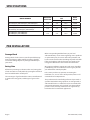
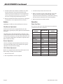
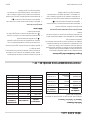
SPECIFICATIONS
MODEL NUMBER
MANIFOLD
INLET SIZE
OPERATING PRESSURE
“WC
INPUT
BTU/H
NATURAL PROPANE
GD-152H(J)(FF), GD-302H(J)(FF), GD-304H(J)(FF)
3/4” 4.0 10.0 14,800
GD-15F(J) 1/2” 4.2 9.0 45,000
GD-15G(J)(FF), GD-15GTH(J), GD-24G(J)(FF),
GD-24GTH(J), GD-36G(J)(FF), GD-36GTH(J)
3/4” 4.0 10.0 20,000
GD-18RB(J)(FF), GD-24RB(J)(FF),
GD-30RB(J)(FF), GD-36RB(J)(FF)
3/4” 4.0 10.0 15,000

Part # 4519762 (12/07) Page 5
INSTALLATION
General
1. Carefully remove unit from carton or crate. Burner tie
wires and other packing material should be removed
from units. On stainless steel units, the protective
material covering the stainless steel should be removed
immediately after the unit is installed.
2. Remove top grates and place in a safe area to prevent
damage.
3. Should it be necessary to remove the steel griddle plate
on units equipped with griddle thermostats, the griddle
thermostat bulb and capillary must rst be withdrawn
from the bulb shield assembly, located on the underside
of the griddle plate. This can be accomplished with the
griddle front raised and supported by the griddle prop
located on the underside of the griddle plate. Loosen the
four pal nuts securing the bulb shield assembly to the
griddle plate and withdraw the griddle thermostat bulb.
4. When a griddle plate is being installed on units equipped
with griddle thermostats, the thermostat bulb must
be inserted in the groove between the plate and the
bulb shield assembly. This can be accomplished with
the griddle front raised and supported by the griddle
prop, located on the underside of the griddle plate. It is
important for accurate temperature control that the bulb
be located inside the groove. Tighten the four pal nuts
securing the bulb shield assembly to the griddle plate.
5. These units must be installed under an adequate
ventilation system. Refer to section titled Ventilation for
further instructions.
6. All burner adjustments and setting shall be made by a
qualied gas technician.
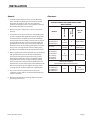
Clearances
MINIMUM INSTALLATION CLEARANCES TO
ADJACENT COMBUSTIBLE/NON-COMBUSTABLE
WALLS OR BASE
Model #
Sides & Back
Floor Or
Base
Combustible
Non
Combustible
GD-152H(J)(FF),
GD-302H(J)(FF),
GD-304H(J)(FF)
6”
(152mm)
0” Combustible
GD-15F(J)
6”
(152mm)
0”
Non
Combustible
GD-15G(J)(FF),
GD-25G(J)(FF),
GD-36G(J)(FF),
GD-15GTH(J),
GD-24GTH(J),
GD-36GTH(J)
6”
(152mm)
0” Combustible
FOR INSTALLATION IN
NON COMBUSTIBLE LOCATIONS ONLY
GD-18RB(J)(FF),
GD-24RB(J)(FF),
GD-30RB(J)(FF),
GD-36RB(J)(FF)
N/A 0”
Non
Combustible

Part # 4519762 (12/07)Page 6
INSTALLATION Continued
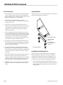
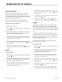
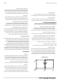
Leg Installation
The leg channel is located on the package base. This channel
must be installed when using the legs.
BOTTOM OF UNIT
LEG CHANNEL
(QTY 2)
4" [102mm]
ADJUSTABLE LEG
(QTY 4)
LEG INSTALLATION
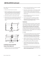
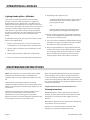
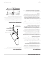
Installation of Banking Plates
All units may be installed independently or banked with
other GD or ED Series equipment. To ensure a matching
and permanent t between units, two banking plates are
available for each unit to be installed. One at the front and
one at the rear of each two units being banked together.
1. Level each unit by adjustment of leveling bolts or legs.
Use a spirit level and level unit four ways; across front and
back and down left and right edges. Level all other units
to the rst unit.
Gas Connections
1. The installation and connection must comply with local
codes, or in the absence of local codes, with CAN/CGA-
B149 Installation Code or with the national Fuel Gas Code,
ANSI Z223.1/NFPA No. 54 – Latest Edition.
2. The correct type of gas for which the unit was
manufactured is noted on the rating plate, and this type
of gas must be used.
3. The gas pressure must be checked when the unit is
installed, to ensure that the unit gas pressure is the same
as specied on the rating plate. If necessary, pressure
adjustments can be made at the pressure regulator,
supplied on each unit.
4. Have a qualied gas technician check the gas pressure
to make certain that existing gas facilities (meter, piping,
etc.) will deliver the BTU’s of gas required at the unit with
no more than ½” water column pressure drop. When
checking pressure, be certain that all the equipment on
same gas line is turned to the “ON” position.
5. The appliance and its individual shut o valve must be
disconnected from the gas supply piping system during
any pressure testing of that system at test pressures in
excess of 1/2 PSIG. (3.45 KPA).
6. The appliance must be isolated from the gas supply
piping system by closing its individual manual shut o
valve during any pressure testing of the gas supply piping
system at test pressures equal to or less than 1/2 PSIG.
(3.45 KPA).
7. Make certain that the new piping, joints and connections
have been made in a clean manner and have been
purged, so that the piping compound, chips, etc., will not
clog pilots, valves and/or controls. Use pipe joint sealant
that is certied for use with liqueed petroleum gas.
8. WARNING: Check gas connections for leaks, using soap
solution or similar means. Do Not Check with an Open
Flame.

Part # 4519762 (12/07) Page 7
Note: Griddles may not rest evenly on the unit body if units
are not leveled.
2. Remove sheet metal screws at rear of unit.
3. Attach one banking plate in position at rear by placing
the 1/4” (6 mm) diameter holes in the banking plate
over the screw holes in the rear of units and fasten by
replacing the sheet metal screws removed in Step 2.
4. Push units into position on counter top or back bar.
5. Remove the two acorn nuts from the sides being banked
(one for each control panel). Place banking plate over
the two protruding screw heads, replace acorn nuts and
tighten.
REAR VIEW
FRONT VIEW
Installation of Non-Combustible
Counter Stands (Optional)
1. Assemble and level counter stand as illustrated in the
instructions found in the counter stand carton.
2. Remove and discard leveling bolts on unit to be installed
on a non-combustible counter stand.
3. Place units in desired position on counter stand, securing
the rst unit with 8-32 machine screws and at washers.
Insert 8-32 machine screws through the 7/32” (5 mm)
diameter holes in stand into the nutserts in the bottom of
GD Series units.
4. Connect banking plates as described in section titled.
Installation of Banking Plates.
5. Secure last unit to counter stand with 8-32 machine
screws and at washers. Insert 8-32 machine screws
through the 7/32” (5 mm) diameter holes in stand into
nutserts in the bottom of GD Series units
Ventilation
Counter equipment must be installed in a location in which
the facilities for ventilation permit satisfactory combustion
of gas and proper venting. Proper ventilation is imperative
for good operation of the appliance. The ideal method
of ventilating counter equipment is the use of a properly
designed ventilating canopy, which should extend at least
6”/152mm beyond all sides of the appliance (except against
the wall if the canopy is a wall installation). This is usually part
of a mechanical exhaust system.
Air Supply
1. It is necessary that sucient room air ingress be allowed
to compensate for the amount of air removed by any
ventilating system. Otherwise, a subnormal atmospheric
pressure will occur, aecting the appliance operation
adversely and causing undesirable working conditions.
2. Appliances shall be located so as not to interfere with
proper circulation of air within the conned space. All gas
burners and pilots require sucient air to operate.
3. Large objects should not be placed in front of the
appliance which might obstruct the air ow through
the front. Do not obstruct the ow of combustion and
ventilation air.
4. Do not permit fans to blow directly at the appliance, and
wherever possible, avoid open windows adjacent to the
appliance sides and back; also wall type fans which create
air cross-currents within the room.
INSTALLATION Continued

Part # 4519762 (12/07)Page 8
ADJUSTMENTS
Burner Adjustments – All Units
1. Before making any adjustment, turn all gas valves
to “OFF”. Remove the burner tie wires, if not already
removed. Be sure all piping is gas tight and that air is
purged from lines.
2. All units are shipped from factory at burner ratings set
for the gas specied on the rating plate at normal gas
pressure. The only adjustment necessary is for that
governing air.
Air Adjustment: If necessary, the air is adjusted by rotating
the air shutter on burner. The burner must have enough air
that the tips of the ames are not yellow, but not so much air
that the ames will lift o the burner ports. Securely tighten
air shutter screw so air shutter cannot be moved.
Hot Plates
IMPORTANT: The ue must be installed prior to start-up.
Pilot Burner Adjustment
Each burner in the hot plate is equipped with a pilot. The
burner pilot is ignited by the piezo ignitor located behind the
front door.
The pilot has been adjusted at the factory; however, it may
require adjustments once installed. The pilot adjusting valve
is located under each burner valve.
Open the bottom door and use a long thin straight blade
screwdriver to adjust the valve. Refer to Flame Size Chart.
Burner Operation
The burner will light automatically from the pilot. Turn the
valve to the full “ON” position. Once the ame has ignited,
adjust the valve to the desired setting.
Fryers
Before Operating the Fryer
1. Before leaving the factory, the fryer was tested and the
thermostat calibrated with oil in the fry tank; therefore, it
is necessary to clean the fry tank before lling with frying
compound. Use detergent or other cleaning agents, with
hot water. Thoroughly rinse and dry fry tank.
2. BEFORE LIGHTING THE PILOT, ll the fry tank. NEVER
OPERATE THE PILOT OR BURNER WITH AN EMPTY FRY
TANK. It only takes a few minutes to completely ruin a fry
tank and void the warranty.
3. WARNING: When fryers are in use, fryer restraint chains/
cables must be installed in order to prevent the fryer from
tipping and splashing hot liquid. Hot shortening causes
severe burns. Never attempt to move a fryer when the
frypot is full. Drain frypot completely before moving fryer.
Pilot Burner Adjustment
1. Turn thermostat knob to lowest position.
2. Depress and turn automatic gas valve knob to “OFF”
position. Caution: Wait 5 minutes before lighting or
relighting pilot.
3. Turn automatic gas valve knob to “Pilot” position.
4. Push knob in, light pilot, and continue to hold knob in for
about 60 seconds after pilot light is lit.
5. Adjust pilot ame to 3/4” (19 mm).
6. If pilot does not continue to burn after releasing button,
repeat above procedure or…
7. Have a qualied Serviceman check the system. DO NOT
ALLOW ANYONE ELSE TO ATTEMPT REPAIRS.
To Operate Main Burner
1. If liquid frying compound is used, the main burner may
be turned on.
2. To ignite burner, turn automatic gas valve
counterclockwise to the “ON” position.
3. If a Hydrogenated (SOLID) frying compound is used,
pack the tank with compound and turn the main burner
on for approximately ve seconds and turn it o for
approximately ten seconds. Repeat until compound
is melted. If any smoke is seen during the process, the
heating action is being carried out too fast and the
frying compound is being scorched as well as possibly
damaging the fry tank.

Part # 4519762 (12/07) Page 9
Shutdown Instructions
To shut down fryer for a short period, turn automatic gas
valve knob to the “PILOT” position.
For complete shutdown, turn automatic gas valve knob
clockwise to “PILOT” position, depress the knob, turn slightly
clockwise, release, and continue to turn clockwise to “OFF”.
Calibration Instructions
1. Field calibration is seldom necessary and should not
be attempted unless experience with cooking results
denitely proves that the control is not maintaining the
temperature to which the dial is set.
2. Suspend thermometer or thermocouple in the middle
of the fry tank, approximately 2” (51 mm) below the
shortening level.
3. Allow burner to cycle at least four times.
4. When the burner just cycles o after the fourth cycle,
compare reading of the thermometer or thermocouple
with thermostat setting.
5. If the two do not agree, ± 10°F (5°C), loosen the two set
screws on the thermostat knob.
6. Set the pointer at the temperature indicated by the
thermometer.
7. Tighten the set screw rmly.
8. Ensure the back surface of the knob is spaced away from
the dial plate at least the thickness of a dime.
NOTE: Do not turn adjusting shaft more than two turns in
either direction or permanent damage can result. This action
will void the Standard Fenwal thermostat warranty.
Griddles
IMPORTANT: The ue must be installed prior to start-up.
Lighting Instructions And
Pilot Burner Adjustment
Each griddle burner is equipped with a pilot.
For the HI-LO valve operated model, the pilot adjusting valve
pilot burner is located on the manifold to the left of each
griddle valve. Open the pilot valve with a screwdriver and
light the pilot with a match.
ADJUSTMENTS Continued
For the griddle equipped with thermostats the pilot and the
main burner are controlled by the ON-OFF valve. MAKE SURE
THE THERMOSTAT IN ON OFF POSITION. Turn on the main
valve and light the pilot with a match. The pilot adjusting
screw is located at the bottom of the thermostat.
Pilots ames must be 3/4 inch (19mm) long
Burner Operation
The burner will light automatically from the pilot. Turn the
valve to full “ON” position. Once the ame has ignited, adjust
the valve to the desired setting.
Hi-Lo Valve Adjustment
Griddles equipped with Hi-Lo valves require a low ame
setting. To adjust, proceed as follows:
1. Burner must be cold.
2. Be sure pilot ames are lit, and adjusted.
3. Turn dial to “LO” position, then remove dial.
4. With a screwdriver, turn the small adjusting screw inside
the valve stem and adjust to obtain the low cooking
temperature desired, maintaining a stable ame covering
the entire burner (minimum 3/16 inch (5 mm) long
ame).
5. Replace dial and turn to “OFF” position.
Calibration Instructions
1. Use a test instrument with a special disc type
thermocouple or a reliable surface type pyrometer. Note:
a drop of oil on the face of the disc will provide better
contact with the plate.
2 Set all griddle thermostats to 350°F (177°C). In order
to allow the griddle temperature to stabilize, the
thermostats must be allowed to cycle twice before taking
a test reading.
3. Check the griddle temperature when the thermostat
just cycles “OFF” by placing the thermocouple rmly on
the griddle surface directly above the sensing bulb of
the thermostat. The reading should be between 335°F
(168°C) and 365°F (185°C). If the reading is outside of
these limits, calibrate as follows:
4. Carefully remove the dial, not disturbing the shaft
position.

Part # 4519762 (12/07)Page 10
ADJUSTMENTS Continued
5. Hold the shaft steady and with a small at screw driver
turn the calibration screw located inside the shaft
clockwise to decrease temperature or anti-clockwise to
increase temperature. Note: Each 1/4 turn of the screw
will create a change of approximately 25°F (14°C).
6. Replace the thermostat dial and repeat steps 1 through 3
to verify that a correct adjustment has been made.
Broilers
IMPORTANT: The ue must be installed prior to start-up.
Pilot Burner Adjustment
Each burner in the broiler is equipped with a pilot. The
burner pilot is ignited by the piezo ignitor located behind the
front door.
The pilot has been adjusted at the factory; however, it may
require adjustment once installed. The pilot adjusting valve is
located under each burner valve. Open the bottom door and
use a long thin straight blade screwdriver to adjust the valve.
Refer to Flame Size Chart.
Burner Operation
The burner will light automatically from the pilot. Turn the
valve to the full “ON” position. Once the ame has ignited,
adjust the valve to the desired setting.
HI-LO Valve Adjustment
Broilers are equipped with HI-LO valves which require a low
ame setting. To adjust, proceed as follows:
1. Burner must be cold.
2. Be sure pilot ames are lit and adjusted.
3. Turn dial to “LO” position, then remove dial.
4. With a screwdriver, turn the small adjusting screw inside
the valve stem and adjust to obtain the low cooking
temperature desired, maintaining a stable ame covering
the entire burner (minimum 3/16” (5 mm) long ame).
5. Replace dial and turn to “OFF” position.
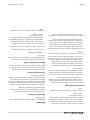
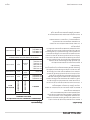
Flame Size
Flame Size Chart
The correct air and/or gas adjustment has been made when
a stable blue inner cone is obtained.
MODEL
NUMBER
DESCRIPTION
PILOT FLAME
LENGTH
GD-152H(FF) Hot Plate 1/2” [13 mm]
GD-302H(FF) Hot Plate 1/2” [13 mm]
GD-304H(FF) Hot Plate 1/2” [13 mm]
GD-15F Fryer 3/4” [19 mm]
GD-15G(FF) Griddle 3/4” [19 mm]
GD-15GTH Griddle 3/4” [19 mm]
GD-24G(FF) Griddle 3/4” [19 mm]
GD-24GTH Griddle 3/4” [19 mm]
GD-36G(FF) Griddle 3/4” [19 mm]
GD-36TGTH Griddle 3/4” [19 mm]
GD-18RB(FF) Broiler 1/2” [13 mm]
GD-24RB[FF] Broiler 1/2” [13 mm]
GD-30RB(FF) Broiler 1/2” [ 13 mm]
GD-36RB(FF) Broiler 1/2” [13 mm]

Part # 4519762 (12/07) Page 11
OPERATION FOR “FF” MODELS
Open Type Hot Plate
All burners are equally rated and may be used either for
fast boiling or simmering. The pan supports will safely
accommodate pans from 125mm (5”) diameter. It is, however,
recommended that pans larger than 30mm (12”) diameter
should be heated on the rear burners.
NOTE: For maximum eciency and stability, use at
bottomed utensils and place centrally over burner head.
Lighting the Open Type Hot Plate
To light the open top burners:
1.
Push in the tap and turn it anti-clockwise to the ignition
position “
”.
2. Holding the tap fully in, depress the ignitor button and
observe that the pilot lights. If it does not, repeatedly
depress the ignitor button until it does.
3. When the pilot is lit, continue to hold the tap in for 20
seconds, then release it. If the pilot goes out, wait for 5
minutes, then repeat from step 1.
4. When the pilot is established, push the tap in again and
turn it anti-clockwise to the full flame position “
” to light
the main burner
.
5
. To shut the burner off, turn the dial to the “
”
position and the safety device will disengage within 60
seconds.
Broilers
Lighting the Broiler
1. Push in the tap and turn it anti-clockwise to the ignition
position
“
”
2. Holding the tap fully in, depress the ignitor button and
observe that the pilot lights. If it does not, repeatedly
depress the ignitor button until it does.
3. When the pilot is lit, continue to hold the tap in for 20
seconds, then release it. If the pilot goes out, wait for 5
minutes, then repeat from step 1.
4. When the pilot is established, push the tap in again and
turn it anti-clockwise to the full ame position “
” to light
the main burner.
5. For low ame or simmer, push the tap in and turn it anti-
clockwise to the
“
”
position.
6. To shut the burner o, turn the dial to the “
” position
and the safety device will disengage within 60 seconds.
Griddles
Griddle tops are designed to have food cooked directly on
the surface. Do not put pots or pans on the griddle surface.
This will scratch or nick the surface and result in improper
cooking or sticking of product. Never salt food over a griddle
since this will build up a gummy residue making it dicult to
clean.
Avoid hitting the surface of the griddle with the edge of a
spatula since this will cause nicks. The most frequently used
temperatures are 300°F (149°C )to 350°F (177°C). After one
ring, the griddle plate will discolour. This is normal and will
not aect cooking performance.
Check the grease container and drain frequently during
heavy use to prevent overow.
Lighting the Griddle
1. Push in the tap and turn it anti-clockwise to the ignition
position “
”.
2. Holding the tap fully in, depress the ignitor button and
observe that the pilot lights. If it does not, repeatedly
depress the ignitor button until it does.
3. When the pilot is lit, continue to hold the tap in for 20
seconds, then release it. If the pilot goes out, wait for 5
minutes, then repeat from step 1.
4. When the pilot is established, push the tap in again and
turn it anti-clockwise to the full ame position “
” to light
the main burner.
5. For low ame or simmer, push the tap in and turn it anti-
clockwise to the “
” position.
6. To shut the burner o, turn the dial to the “
” position
and the safety device will disengage within 60 seconds.

Part # 4519762 (12/07)Page 12
Lighting Standing Pilots - All Models
These units are not designed to be disconnected from
their gas connections and re-installed on a regular basis.
Quick connect gas lines should not be used. Once the gas
appliance has been installed by a licensed gas trades-person
all connections, pilot lights and controls have been inspected
for proper operation. All gas appliances that use standing
pilot systems are generally assumed to be operating with
the pilot on continuously. The units should not be restarted
except in the event of a gas service interruption to the
facility.
If a pilot ame does go out, here are the basic steps to check
before you re-light the pilot:
1. Check to see that all gas lines are in place and secured
and that there is no accumulation of gas inside the unit.
2. Check to make sure that the main shut o valve is in the
o position.
3. Turn the thermostat to the o position. (If applicable)
4. Turn on or open the main shut o valve to the appliance.
OPERATION ALL MODLES
5. Depending on the appliance type:
Lower the front black enamel panel to the unit and
immediately depress the red button, which is the
piezo to ignite the pilot.
Or.
Remove the front valve panel and light the pilot
with a lighted taper, through pilot viewing hole.
6. The pilot should ignite within a few attempts. You will be
able to see the pilot ame through the observation hole
in the stainless steel front panel.
7. If you do not have a pilot ame established fairly quickly
and begin to smell gas, shut o the main valve and wait
ve minutes to let the gas build-up escape.
8. Only once the pilot ame has been established should
you turn on the burner control. When the burner control
is on it allows gas ow to the burner. If there is no pilot
ame it will allow gas to build up and cause possible
delayed ignition, which could result in an explosion.
MAINTENANCE INSTRUCTIONS
NOTE: Any maintenance or service involving disassembly
of components should be made by a qualied service
technician. Also, ensure gas supply to the appliance is shut
o.
You have purchased the nest commercial cooking
equipment available anywhere. Like any other ne precision
built piece of equipment, it should be given regular care and
maintenance.
Periodical inspections by your dealer or qualied service
agency are recommended to check temperatures,
adjustments and ensure moving parts are operative.
Whenever possible, avoid overheating idle equipment as this
is the primary cause for increased service costs.
When corresponding with the factory or your equipment
dealer regarding service problems or replacement parts,
be sure to refer to the particular unit by the correct model
number (including prex and sux letters and numbers) and
the serial or code number. The rating plate axed to the unit
contains this information.
“Regular Maintenance Ensures Peak Performance.”
Cleaning Instructions
Black Baked Enamel – Allow equipment to cool after use
and wash all grease deposits from exterior with a hot mild
detergent or soap solution. Dry thoroughly. Do not use
abrasives.
Nickel Plated – Wash when cool with a hot mild detergent or
soap solution. Do not use abrasives.
Stainless Steel – Normal soil may be removed with a
detergent or soap solution applied with a cloth.

Part # 4519762 (12/07) Page 13
To remove grease that has baked on, apply cleanser to a
damp cloth or sponge and rub cleanser on the metal. NEVER
RUB WITH A CIRCULAR MOTION. Soil and burnt deposits
which do not respond can usually be removed by rubbing
the surface with Scotch-Brite scouring pads or Stainless
scouring pads. DO NOT USE ORDINARY STEEL WOOL.
Heat tint can be removed by a vigorous scouring in the
direction of the polish lines using Scotch-Brite scouring pads
or a Stainless scouring pad in combination with a powdered
cleanser.
MAINTENANCE INSTRUCTIONS Continued
PARTS AND SERVICE
It is easy to keep your Garland equipment working in top
condition.
Technical information and/or parts literature is available
through your local Authorized Garland Service Agency or
direct from Garland.

Part # 4519762 (12/07)Page 14

Pièce nº 4519762 (12/07)Page 14
PIÈCES DE RECHANGE ET RÉPARATION
Il est facile de maintenir votre équipement Garland en bon
état de marche.
Vous pouvez obtenir des renseignements techniques et/ou
de la documentation sur les pièces auprès de votre agence
de service agréée Garland ou directement auprès de Garland.
Instructions De Nettoyage
Émail noir – Laisser l’équipement refroidir après utilisation et
laver tous les dépôts graisseux à l’extérieur avec une solution
très chaude de détergent doux ou de savon. Bien sécher. Ne
pas utiliser de produits abrasifs.
Pièces nickelées – Les laver une fois froides avec une solution
très chaude de détergent doux ou de savon. Ne pas utiliser
de produits abrasifs.
Acier inoxydable – Les salissures normales peuvent être
éliminées avec une solution de détergent ou de savon
appliquée avec un chi on.
INSTRUCTIONS D’ENTRETIEN suite
Pour éliminer la graisse cuite, appliquer du produit de
nettoyage sur un chi on humide ou une éponge et faire
couler le produit sur le métal. NE JAMAIS FROTTER AVEC
UN MOUVEMENT CIRCULAIRE. La saleté et les dépôts brûlés
qui ne se détachent pas ainsi peuvent habituellement être
éliminés en frottant la surface avec des tampons à récurer
Scotch-Brite ou des tampons à récurer pour acier inoxydable.
NE PAS UTILISER DE LAINE D’ACIER ORDINAIRE.
La coloration causée par la chaleur peut être éliminée en
frottant vigoureusement dans le sens des lignes de polissage
avec des tampons à récurer Scotch-Brite ou un tampon à
récurer pour acier inoxydable combinés à un produit de
nettoyage en poudre.

Pièce nº 4519762 (12/07) Page 13
Allumage Des Veilleuses Permanentes –
Tous Modèles
Ces appareils ne sont pas conçus pour être débranchés de la
conduite de gaz et être rebranchés de façon régulière. On ne
devra pas utiliser de conduites à raccord rapide. Une fois que
l’appareil à gaz a été installé par un professionnel licencié,
le fonctionnement correct des branchements, veilleuses
et commandes doit être véri é. On suppose généralement
que tous les appareils à gaz qui utilisent des systèmes de
veilleuses permanentes fonctionnent de façon continue avec
les veilleuses allumées. Les appareils ne devraient pas être
rallumés, sauf en cas de coupure de gaz dans les installations.
Si la veilleuse s’éteint, véri ez ce qui suit avant de rallumer la
veilleuse :
1. Véri ez que toutes les conduites de gaz sont en place
et bien xées et qu’il n’y a pas d’accumulation de gaz à
l’intérieur de l’appareil.
2. Véri ez que le robinet d’arrêt principal est en position
fermée.
3. Tournez le thermostat en position d’arrêt. (Le cas échéant)
4. Ouvrez le robinet d’arrêt de l’appareil.
UTILISATION DE TOUS LES MODÈLES
5. Selon le type d’appareil :
Abaissez le panneau avant émaillé noir de l’appareil
et appuyez immédiatement sur le bouton rouge,
correspondant à l’allumeur piézoélectrique de la
veilleuse.
Ou
Retirez le panneau avant des robinets et allumez la
veilleuse avec une mèche allumée, à travers le trou
d’observation de la veilleuse.
6. La veilleuse devrait s’allumer au bout de quelques essais.
Vous pourrez voir la amme de la veilleuse par le trou
d’observation dans le panneau avant en acier inoxydable.
7. Si la veilleuse ne s’allume pas rapidement et que vous
sentez une odeur de gaz, fermez le robinet principal
et attendez cinq minutes pour que le gaz accumulé se
dissipe.
8. Ne pas tourner la commande de brûleur avant que la
amme de veilleuse ne soit établie. Quand la commande
de brûleur est ouverte, le gaz peut parvenir au brûleur.
Si la veilleuse n’est pas allumée, le gaz s’accumule et un
allumage retardé pourrait causer une explosion.
INSTRUCTIONS D’ENTRETIEN
NOTA : Tout entretien ou réparation impliquant le
démontage de composants devra être e ectué par un
technicien d’entretien quali é. Véri er également que
l’alimentation en gaz de l’appareil est coupée.
Vous avez acheté le meilleur équipement commercial de
cuisson au monde. Comme tout autre équipement fabriqué
avec précision, il devra être nettoyé et entretenu de façon
régulière.
Des inspections périodiques par le concessionnaire ou
une agence d’entretien quali ée sont recommandées
pour véri er les températures, les réglages et s’assurer
que les pièces mobiles fonctionnement correctement. Si
possible, éviter de surchau er l’équipement inutilisé, car cela
représente la principale cause de coûts d’entretien.
Pour correspondre avec l’usine ou votre concessionnaire en
équipement concernant des problèmes de service ou des
pièces de rechange, bien faire référence à l’appareil avec
le numéro de modèle correct (comprenant les lettres et
chi res du pré xe et du su xe) et le numéro de série ou de
code. La plaque signalétique xée à l’appareil contient ces
renseignements
“Un entretien régulier assure des performances optimales.”

Pièce nº 4519762 (12/07)Page 12
3. Une fois la veilleuse allumée, continuer de maintenir le
robinet enfoncé pendant 20 secondes, puis le relâcher. Si
la veilleuse s’éteint, attendre 5 minutes et recommencer à
partir de l’étape 1.
4. Quand la veilleuse est bien allumée, appuyer de nouveau
sur le robinet et le tourner complètement dans le sens
contraire des aiguilles d’une montre jusqu’à la position
«
» pour allumer le brûleur principal.
5. Pour obtenir une amme basse ou pour mijoter, appuyer
sur le robinet et le tourner dans le sens contraire des
aiguilles d’une montre jusqu’à la position « ».
6. Pour éteindre le brûleur, tourner le cadran à la position
«
» et le dispositif de sécurité se désengagera dans un
délai de 60 secondes.
Grils
Les grils sont conçus pour cuire les aliments directement sur
leur surface. Ne pas placer de pot ni de plats à la surface du
gril. Cela risque de rayer ou d’entailler la surface et de causer
des problèmes de cuisson ou d’adhérence des aliments.
Ne jamais saler les aliments sur un gril car un résidu collant
s’accumulera, rendant di cile le nettoyage du gril.
Éviter de heurter la surface du gril avec le bord d’une spatule
car cela causera des entailles.
Les températures le plus souvent utilisées vont de 300°F
(149°C ) à 350°F (177°C). Après une cuisson, la plaque du gril
va se décolorer. Cela est normal et n’a ectera pas les résultats
de cuisson.
Véri er et vider fréquemment le contenant à graisse en cas
d’utilisation intensive pour éviter tout débordement.
Allumage Du Gril
1. Enfoncer le robinet et le tourner dans le sens inverse des
aiguilles d’une montre jusqu’à la position
«
».
2. En maintenant le robinet enfoncé, appuyer sur le bouton
de l’allumeur et véri er que la veilleuse s’allume. Si elle
ne s’allume pas, continuez d’appuyer sur le bouton de
l’allumeur jusqu’à ce qu’elle s’allume.
3. Une fois la veilleuse allumée, continuer de maintenir le
robinet enfoncé pendant 20 secondes, puis le relâcher. Si
la veilleuse s’éteint, attendre 5 minutes et recommencer à
partir de l’étape 1.
4. Quand la veilleuse est bien allumée, appuyer de nouveau
sur le robinet et le tourner complètement dans le sens
contraire des aiguilles d’une montre jusqu’à la position
«
» pour allumer le brûleur principal.
5. Pour obtenir une amme basse ou pour mijoter, appuyer
sur le robinet et le tourner dans le sens contraire des
aiguilles d’une montre jusqu’à la position « ».
6. Pour éteindre le brûleur, tourner le cadran à la position
«
» et le dispositif de sécurité se désengagera dans un
délai de 60 secondes.
FONCTIONNEMENT DES MODÈLES « FF » suite

Pièce nº 4519762 (12/07) Page 11
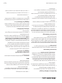
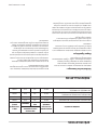
Taille Des Flammes
Tableau De Taille Des Flammest
Le réglage d’air et/ou de gaz est correct quand on obtient un
cône intérieur bleu stable.
NUMÉRO DE
MODÈLE
DESCRIPTION
LONGUEUR DE
FLAMME DE
VEILLEUSE
GD-152H(FF) Plaque
Chau ante
1/2” [13 mm]
GD-302H(FF) Plaque
Chau ante
1/2” [13 mm]
GD-304H(FF) Plaque
Chau ante
1/2” [13 mm]
GD-15F Friteuse 3/4” [19 mm]
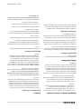
NUMÉRO DE
MODÈLE
DESCRIPTION
LONGUEUR DE
FLAMME DE
VEILLEUSE
GD-15G(FF) Gril 3/4” [19 mm]
GD-15GTH Gril 3/4” [19 mm]
GD-24G(FF) Gril 3/4” [19 mm]
GD-24GTH Gril 3/4” [19 mm]
GD-36G(FF) Gril 3/4” [19 mm]
GD-36TGTH Gril 3/4” [19 mm]
GD-18RB(FF) Rôtissoire 1/2” [13 mm]
GD-24RB[FF] Rôtissoire 1/2” [13 mm]
GD-30RB(FF) Rôtissoire 1/2” [ 13 mm]
GD-36RB(FF) Rôtissoire 1/2” [13 mm]
RÉGLAGES suite
FONCTIONNEMENT DES MODÈLES « FF »
Plaques Chau antes De Type Ouvert.
Tous les brûleurs ont un débit calori que identique et
peuvent être utilisés indi éremment pour faire bouillir
rapidement ou laisser mijoter. Les supports de plat peuvent
accueillir en toute sécurité des plats à partir de 125 mm
(5 po) de diamètre. Cependant, il est recommandé de faire
chau er sur les brûleurs arrière les plats dont le diamètre est
supérieur à 30 mm (12 po).
NOTA : Pour une e cacité et une stabilité maximales, utiliser
des ustensiles à fond plat et les placer au centre de la tête de
brûleur.
Allumage De La Plaque Chau ante De Type Ouvert
Pour allumer les brûleurs de plaque ouverte.
1. Enfoncer le robinet et le tourner dans le sens inverse des
aiguilles d’une montre jusqu’à la position «
».
2. En maintenant le robinet enfoncé, appuyer sur le bouton
de l’allumeur et véri er que la veilleuse s’allume. Si elle
ne s’allume pas, continuez d’appuyer sur le bouton de
l’allumeur jusqu’à ce qu’elle s’allume.
3. Une fois la veilleuse allumée, continuer de maintenir le
robinet enfoncé pendant 20 secondes, puis le relâcher. Si
la veilleuse s’éteint, attendre 5 minutes et recommencer à
partir de l’étape 1.
4. Quand la veilleuse est bien allumée, appuyer de nouveau
sur le robinet et le tourner complètement dans le sens
contraire des aiguilles d’une montre jusqu’à la position
« » pour allumer le brûleur principal.
5. Pour éteindre le brûleur, tourner le cadran à la position
«
» et le dispositif de sécurité se désengagera dans un
délai de 60 secondes.
Rôtissoires
Allumage de la rôtissoire
1. Enfoncer le robinet et le tourner dans le sens inverse des
aiguilles d’une montre jusqu’à la position
«
»
.
2. En maintenant le robinet enfoncé, appuyer sur le bouton
de l’allumeur et véri er que la veilleuse s’allume. Si elle
ne s’allume pas, continuez d’appuyer sur le bouton de
l’allumeur jusqu’à ce qu’elle s’allume.

Pièce nº 4519762 (12/07)Page 10
RÉGLAGES suite
4. Avec un tournevis, tourner la petite vis de réglage à
l’intérieur de la tige du robinet et régler pour obtenir la
température basse de cuisson souhaitée, maintenant une
amme stable couvrant tout le brûleur ( amme d’une
longueur minimale de
3/16 po (5 mm)).
5. Remettre en place le cadran et le tourner en position
« OFF ».
Instructions D’étalonnage
1. Utiliser un instrument d’essai avec un thermocouple
spécial de type à disque ou un pyromètre able de type
“ surface ”. Nota : une goutte d’huile sur la face du disque
assurera un meilleur contact avec la plaque.
2. Régler tous les thermostats de grils à 350°F (177°C). Pour
permettre à la température du gril de se stabiliser, il faut
laisser les thermostats cycler deux fois avant de mesurer
la température.
3. Véri er la température du gril quand le thermostat
vient juste de s’éteindre en appuyant fermement le
thermocouple sur la surface du gril, directement au-
dessus du bulbe thermostatique. Le résultat devrait être
compris entre 335°F (168°C) et 365°F (185°C). Si le résultat
est hors de ces limites, étalonner comme indiqué ci-après:
4. Retirer soigneusement le cadran, sans modi er la position
de l’axe.
5. En immobilisant l’axe, tourner avec un petit tournevis plat
la vis d’étalonnage à l’intérieur de l’axe dans le sens des
aiguilles d’une montre pour diminuer la température ou
dans le sens contraire des aiguilles d’une montre pour
augmenter la température. Nota : Chaque 1/4 de tour de
la vis modi e la température d’environ 25°F (14°C)
6. Remettre en place le cadran du thermostat et répéter les
étapes 1 à 3 pour véri er que le réglage est correct.
Rôtissoires
IMPORTANT : Le conduit de fumée doit être installé avant la
mise en marche.
Réglage Des Veilleuses
Chaque brûleur dans la rôtissoire est équipé d’une
veilleuse. La veilleuse de brûleur est allumée par l’allumeur
piézoélectrique situé derrière la porte avant.
La veilleuse a été réglée en usine; cependant, il est possible
qu’elle ait besoin de réglages une fois installée. Le robinet de
réglage de veilleuse est situé sous chaque robinet de brûleur.
Ouvrir la porte inférieure et utiliser une lame de tournevis
droit long et n pour régler le robinet. Se reporter au tableau
des tailles des ammes.
Utilisation Des Brûleurs
Le brûleur s’allume automatiquement avec la veilleuse.
Tourner le robinet à la position extrême « ON ». Une fois la
amme allumée, régler le robinet selon le réglage souhaité.
Réglage Des Robinets HI-LO
Les rôtissoires dotées de robinets Hi-Lo ont besoin d’un
réglage de amme basse. Pour e ectuer ce réglage, procéder
comme suit :
1. Le brûleur doit être froid.
2. S’assurer que les veilleuses sont allumées et réglées.
3. Tourner le cadran en position « LO » et retirer le cadran.
4. Avec un tournevis, tourner la petite vis de réglage à
l’intérieur de la tige du robinet et régler pour obtenir la
température basse de cuisson souhaitée, maintenant une
amme stable couvrant tout le brûleur ( amme d’une
longueur minimale de
3/16 po (5 mm)).
5. Remettre en place le cadran et le tourner en position
« OFF ».

Pièce nº 4519762 (12/07) Page 9
Pour Utiliser Le Brûleur Principal
1. En cas d’utilisation de produit à friture liquide, il est
possible d’allumer le brûleur principal.
2. Pour allumer le brûleur, tourner le robinet automatique
de gaz dans le sens inverse des aiguilles d’une montre à la
position « ON ».
3. En cas d’utilisation d’un produit à friture hydrogéné
(solide), remplir le bassin avec du produit et allumer le
brûleur principal pendant environ cinq secondes, puis
l’éteindre pendant environ dix secondes. Recommencer
jusqu’à ce que le produit à friture soit fondu. Si de la
fumée se dégage pendant ce processus, le réchau age
est trop rapide et le produit à friture brûle, ce qui risque
d’endommager le bassin de friture.
Instructions D’extinction
Pour éteindre la friteuse pour une courte période de temps,
tournez le bouton du robinet automatique de gaz à la
position “PILOT”.
Pour éteindre complètement l’appareil, tourner le bouton du
robinet automatique de gaz dans le sens des aiguilles d’une
montre à la position « PILOT », appuyer sur le bouton, tourner
légèrement dans le sens des aiguilles d’une montre, relâcher
et continuer de tourner dans le sens des aiguilles d’une
montre jusqu’à « OFF ».
Instructions D’étalonnage
1. L’étalonnage sur place est rarement nécessaire et on ne
devra pas essayer de le faire sauf si les résultats de cuisson
démontrent que les commandes ne maintiennent pas les
températures sur lesquelles sont réglées les commandes.
2. Suspendre un thermomètre ou un thermocouple au
milieu du bain de friture, à environ 2 po (51 mm) sous le
niveau du liquide à friture.
3. Attendre que le brûleur s’allume et s’éteigne au moins
quatre fois.
4. Quand le brûleur vient de s’éteindre après le quatrième
cycle, comparez l’indication du thermomètre ou
thermocouple au réglage du thermostat.
5. S’ils ne correspondent pas ± 10°F (5°C), desserrer les deux
vis de blocage du bouton du thermostat.
6. Régler le pointeur à la température indiquée sur le
thermomètre;
RÉGLAGES suite
7. Bien serrer la vis de blocage.
8. Véri er que la surface noire du bouton est su samment
éloignée de la plaque du cadran (au moins l’épaisseur
d’une pièce de 10 sous).
NOTA : Ne pas tourner l’axe de réglage de plus de deux
tours dans un sens ou dans l’autre sous peine de causer des
dommages permanents. Cela annulera la garantie standard
du thermostat Fenwal.
Grils
IMPORTANT : Le conduit de fumée doit être installé avant la
mise en marche.
Instructions D’allumage Et
Réglage Des Veilleuses
Chaque brûleur du gril est doté d’une veilleuse.
Pour le modèle avec robinets HI-LO, le robinet de réglage
de veilleuse est situé sur le collecteur, à gauche de chaque
robinet de gril. Ouvrir le robinet de veilleuse avec un
tournevis et allumer la veilleuse avec une allumette.
Pour le gril doté de thermostats, la veilleuse et le brûleur
principal sont commandés par le robinet ON-OFF (Marche-
arrêt). VÉRIFIER QUE LE THERMOSTAT EST EN POSITION
D’ARRÊT. Ouvrir le robinet principal et allumer la veilleuse
avec une allumette. La vis de réglage de veilleuse est placée
en bas du thermostat.
Les ammes des veilleuses doivent avoir une longueur de
3/4 po (19 mm).
Utilisation Des Brûleurs
Le brûleur s’allume automatiquement avec la veilleuse.
Tourner le robinet à la position extrême « ON ». Une fois la
amme allumée, régler le robinet selon le réglage souhaité
Réglage Des Robinets Hi-Lo
Les grils dotés de robinets Hi-Lo ont besoin d’un réglage de
amme basse. Pour e ectuer ce réglage, procéder comme
suit :
1. Le brûleur doit être froid.
2. S’assurer que les veilleuses sont allumées et réglées.
3. Tourner le cadran en position “ LO ” et retirer le cadran.
La page charge ...
La page charge ...
La page charge ...
La page charge ...
La page charge ...
La page charge ...
La page charge ...
La page charge ...
-
 1
1
-
 2
2
-
 3
3
-
 4
4
-
 5
5
-
 6
6
-
 7
7
-
 8
8
-
 9
9
-
 10
10
-
 11
11
-
 12
12
-
 13
13
-
 14
14
-
 15
15
-
 16
16
-
 17
17
-
 18
18
-
 19
19
-
 20
20
-
 21
21
-
 22
22
-
 23
23
-
 24
24
-
 25
25
-
 26
26
-
 27
27
-
 28
28


Garland 36ER33-88 Guide d'installation
- Catégorie
- Plaques électriques
- Taper
- Guide d'installation
dans d''autres langues
- English: Garland 36ER33-88 Installation guide
Documents connexes
-
Garland Regal Series Manuel utilisateur
-
Garland E20 Series Manuel utilisateur
-
-
Garland G24-18G Mode d'emploi
-
-
-
-
-
-
Garland E24-12H Guide d'installation