
Dwg Name: HVNCVT-2-1390108ART Dwg No: 1390107
ECO No: 19485 Pkg Dwg Ref: 1290179 Rev: A
Color Reference: CEN-PACK-003-A
INSTRUCTION MANUAL
Français pg. 25
Español pg. 13
ENGLISH
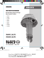
HVNCVT2
Broad-Range High-Voltage
Non-Contact Tester
• TEST
• 240V
• 4.2kV
• 15kV
• 25kV
• 35kV
• 69kV
• 115kV
• 230kV
HVNCVT2-1390108ART.indd 1 7/20/2015 3:25:27 PM

2
Dwg Name: HVNCVT-2-1390108ART Dwg No: 1390107
ECO No: 19485 Pkg Dwg Ref: 1290179 Rev: A
Color Reference: CEN-PACK-003-A
SYMBOLS
Warning or Caution
Risk of Electrical Shock
Double Insulated
GENERAL SPECIFICATIONS
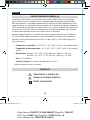
The Broad-Range High-Voltage Non-Contact Tester (HVNCVT2) is an instrument
for verifying the live or de-energized status of conductors and other exposed
electrical equipment. The tester warns against dangerous voltage in several different
ranges without contacting the energized conductor. Only use with hot sticks and
rubber gloves meeting industry standards. Verify the rotary switch setting before
measuring voltage, to ensure it is on the correct setting for your application.
Always follow approved work safety practices and clearances per OSHA Sub-parts
R & V and all company work rules. For Minimum Approach Distances (MAD), see
OSHA Tables R-6 and R-7 (pages 8 & 9) in this manual.
• Operating Temperature: 14° to 122°F (-10° to 50°C) @ 85% relative humidity
• Storage Temperature: -4° to 140°F (-20° to 60°C) @ 85% relative humidity
• Dimensions: Tester: 10" x 4.25" x 4.25" (254 x 108 x 108 mm)
Case: 13.5" x 8.75" x 4.75" (343 x 222 x 121 mm)
• Weight: 1.32 lbs. (600 g)
• Power Source: Three 1.5V "C" cell batteries
Specifications subject to change.
ENGLISH
HVNCVT2-1390108ART.indd 2 7/20/2015 3:25:27 PM

3
Dwg Name: HVNCVT-2-1390108ART Dwg No: 1390107
ECO No: 19485 Pkg Dwg Ref: 1290179 Rev: A
Color Reference: CEN-PACK-003-A
Dwg Name: HVNCVT-2-1390108ART Dwg No: 1390107
ECO No: 19485 Pkg Dwg Ref: 1290179 Rev: A
Color Reference: CEN-PACK-003-A
WARNINGS
To ensure safe operation and service of the tester, follow these instructions.
Failure to observe these warnings can result in severe injury or death.
• Use extreme caution when testing live electrical circuits due to risk of injury from
electrical shock.
• Always use hot sticks and rubber gloves meeting industry standards.
• Follow approved work safety practices and clearances per OSHA Sub-parts
R & V and your company work rules.
• Always test on a known live circuit to verify tester functionality prior to use.
• Do not exceed the limits marked on the instrument itself. Never test voltage
more than 230kV AC RMS.
• Never ground yourself when taking measurements. Do not touch exposed
circuit elements.
• Observe the proper safety precautions when working with voltage above 30V AC
RMS to avoid electrical shock hazard.
• Do not assume equipment or conductors are, or will remain, de-energized.
Always install proper grounding devices before starting procedure.
• Do not operate tester in an explosive atmosphere.
• Do not expose tester to rain or moisture. This increases the risk of fire
or electric shock.
• Do not rely on this tester for shielded wire or cable with concentric neutrals.
• Do not let the unit make contact with live line voltage. Do not touch any exposed
wiring, connections or other energized parts of an electrical circuit.
• 3-phase feeder cables with conductors close to each other may self-cancel the
electric field and not be detected by the device. Verify that the phase conductors
are separated by at least 15" (381 mm) before testing for AC voltage.
• Do not use in an area with mixed high voltages. In the presence of mixed
voltages, the tester may become unreliable.
• Always ensure tester is directly under the conductor being tested. If other live
voltage is nearby, tester may detect adjacent voltage.
HVNCVT2-1390108ART.indd 3 7/20/2015 3:25:27 PM

4
Dwg Name: HVNCVT-2-1390108ART Dwg No: 1390107
ECO No: 19485 Pkg Dwg Ref: 1290179 Rev: A
Color Reference: CEN-PACK-003-A
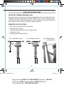
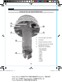
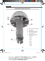
1. Voltage indicator LEDs
2. Buzzer
3. Battery compartment
4. Hot stick connection point
5. Sensitivity selector:
• OFF
• TEST
• 240V
• 4.2kV
• 15kV
• 25kV
• 35kV
• 69kV
• 115kV
• 230kV
FEATURE DETAILS
ENGLISH
3
2
4
5
1 1
1
HVNCVT2-1390108ART.indd 4 7/20/2015 3:25:28 PM

5
Dwg Name: HVNCVT-2-1390108ART Dwg No: 1390107
ECO No: 19485 Pkg Dwg Ref: 1290179 Rev: A
Color Reference: CEN-PACK-003-A
Dwg Name: HVNCVT-2-1390108ART Dwg No: 1390107
ECO No: 19485 Pkg Dwg Ref: 1290179 Rev: A
Color Reference: CEN-PACK-003-A
OPERATING INSTRUCTIONS
FOR USE BY TRAINED PERSONNEL ONLY
Anyone using this instrument should be knowledgeable and trained about the risks
involved with measuring medium and high voltage. They must also understand the
importance of taking safety precautions as well as testing the instrument before and
after using it to ensure that it is in good working condition.
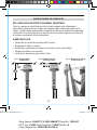
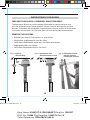
EXAMPLES OF APPLICATIONS:
• Non-contact detection of live AC voltage
• Finding faults in cables
• Checking and detecting live high voltage cables
• Tracing live wires
• Checking grounding equipment
VG
90°
HOT STICK
HOT STICK
Fig. 1: Ideal detection angle Fig. 2: Finding a cable fault Fig. 3: Voltage detection
for overhead lines
HVNCVT2-1390108ART.indd 5 7/20/2015 3:25:28 PM

6
Dwg Name: HVNCVT-2-1390108ART Dwg No: 1390107
ECO No: 19485 Pkg Dwg Ref: 1290179 Rev: A
Color Reference: CEN-PACK-003-A
ENGLISH
OPERATING INSTRUCTIONS
Prior to use, always inspect the tester for visible signs of damage. If there is
any sign of damage, or if the tester does not operate correctly, discontinue use.
Always test on a known live circuit to verify tester functionality. The tester should be used
as an indication only.
Tester should be kept clean and dry. If it is not, wipe with a clean, dry lint-free cloth.
TEST FUNCTION
Turn the sensitivity selector knob
5
to TEST in order to perform a self-test on the
unit. Look for a steady red light from all 3 LEDs
1
and listen for a steady high-pitched
sound. This self-test function confirms battery sufficiency, system integrity, and
operation/active mode. Always test on known live circuit to verify tester functionality
prior to use.
If the 3 red LEDs do not glow and the beep sound is not present, replace
batteries.
240V AC (Secondary Test)
Perform a second test function prior to use by turning the sensitivity selector knob
5
to 240V and placing the dome near a low voltage live conductor. If a low voltage live
conductor is not available, rub the dome against an item of clothing to generate static.
Look for a blinking red light from all 3 LEDs
1
and listen for a beeping sound. See
Fig. 1 on page 5 for ideal detection angle. Always test on known live circuit to verify
tester functionality prior to use.
If the 3 red LEDs do not glow and the beep sound is
not present, replace batteries.
OPERATION
Before using the unit, a hot stick must be attached. Only use with hot sticks and rubber
gloves meeting industry standards. Always follow approved work safety practices and
clearances per OSHA Sub-parts R & V and all company work rules.
Turn the sensitivity selector knob
5
to the appropriate setting. It is recommended to
start with a lower test setting than the actual working voltage, then gradually increase
the setting until the voltage is detected.
Gradually move the tester towards the live conductor until the warning signal is triggered.
See Fig. 1 on page 5 for ideal detection angle. Always maintain the minimum approach
distances listed in OSHA Tables R-6 and R-7 on pages 8 & 9 in this manual.
1. Voltage indicator LEDs
2. Speaker
3. Battery compartment
4. Hot stick connection point
5. Sensitivity selector:
• OFF
• TEST
• 240V
• 4.2kV
• 15kV
• 25kV
• 35kV
• 69kV
• 115kV
• 230kV
HVNCVT2-1390108ART.indd 6 7/20/2015 3:25:28 PM

7
Dwg Name: HVNCVT-2-1390108ART Dwg No: 1390107
ECO No: 19485 Pkg Dwg Ref: 1290179 Rev: A
Color Reference: CEN-PACK-003-A
Dwg Name: HVNCVT-2-1390108ART Dwg No: 1390107
ECO No: 19485 Pkg Dwg Ref: 1290179 Rev: A
Color Reference: CEN-PACK-003-A
OPERATING INSTRUCTIONS
FINDING FAULTS IN CABLE
The tester may be used for finding faults in some flexible cables. Turn the
sensitivity selector knob
5
to the appropriate setting for the energized cable
being detected. Move the detector along (but not touching) the cable, listening for
rapid beeping or steady sound and looking for the rapidly blinking or steady red
light from all 3 LEDs
1
. When the fault is reached, the unit will no longer beep
or blink. See Fig. 2 on page 5. Always maintain the minimum approach distances
listed in OSHA Tables R-6 and R-7 on pages 8 & 9 in this manual.
HVNCVT2-1390108ART.indd 7 7/20/2015 3:25:28 PM

8
Dwg Name: HVNCVT-2-1390108ART Dwg No: 1390107
ECO No: 19485 Pkg Dwg Ref: 1290179 Rev: A
Color Reference: CEN-PACK-003-A
ENGLISH
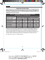
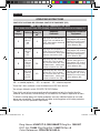
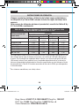
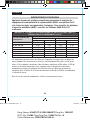
TABLE R-6 – ALTERNATIVE MINIMUM APPROACH DISTANCES
FOR VOLTAGES OF 72.5 kV AND LESS
1
Nominal voltage
(kV)
phase-to-phase
Distance
Phase-to-ground exposure Phase-to-phase exposure
ft. m ft. m
0.050 to 0.300
2
Avoid Contact Avoid Contact Avoid Contact Avoid Contact
0.301 to 0.750
2
1.09 0.33 1.09 0.33
0.751 to 5.0 2.07 0.63 2.07 0.63
5.1 to 15.0 2.14 0.65 2.24 0.68
15.1 to 36.0 2.53 0.77 2.92 0.89
36.1 to 46.0 2.76 0.84 3.22 0.98
46.1 to 72.5 3.29 1.00 3.94 1.20
Employers may use the minimum approach distances in this table provided the worksite is
at an elevation of 3,000 feet (900 meters) or less. If employees will be working at elevations
greater than 3,000 feet (900 meters) above mean sea level, the employer shall determine
minimum approach distances by multiplying the distances in this table by the correction factor
in OSHA's Table R-5 Altitude Correction Factor, corresponding to the altitude of the work.
For single-phase systems, use voltage-to-ground.
OPERATING INSTRUCTIONS
Always follow approved work safety practices and clearances per OSHA Sub-parts
R & V and all company work rules. For Minimum Approach Distances (MAD), see
OSHA Tables R-6 and R-7 below.
1
2
HVNCVT2-1390108ART.indd 8 7/20/2015 3:25:29 PM

9
Dwg Name: HVNCVT-2-1390108ART Dwg No: 1390107
ECO No: 19485 Pkg Dwg Ref: 1290179 Rev: A
Color Reference: CEN-PACK-003-A
Dwg Name: HVNCVT-2-1390108ART Dwg No: 1390107
ECO No: 19485 Pkg Dwg Ref: 1290179 Rev: A
Color Reference: CEN-PACK-003-A
OPERATING INSTRUCTIONS
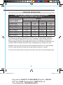
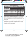
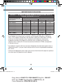
TABLE R-7-ALTERNATIVE MINIMUM APPROACH DISTANCES
FOR VOLTAGES OF MORE THAN 72.5 kV
1 2 3
Nominal voltage
(kV)
phase-to-phase
Distance
Phase-to-ground exposure Phase-to-phase exposure
ft. m ft. m
72.6 to 121.0 3.71 1.13 4.66 1.42
121.1 to 145.0 4.27 1.30 5.38 1.64
145.1 to 169.0 4.79 1.46 6.36 1.94
169.1 to 242.0 6.59 2.01 10.10 3.08
242.1 to 362.0 11.19 3.41 18.11 5.52
362.1 to 420.0 13.94 4.25 22.34 6.81
420.1 to 550.0 16.63 5.07 27.03 8.24
550.1 to 800.0 22.57 6.88 37.34 11.38
Employers may use the minimum approach distances in this table provided the worksite is
at an elevation of 3,000 feet (900 meters) or less. If employees will be working at elevations
greater than 3,000 feet (900 meters) above mean sea level, the employer shall determine
minimum approach distances by multiplying the distances in this table by the correction factor
in OSHA's Table R-5 Altitude Correction Factor, corresponding to the altitude of the work.
Employers may use the phase-to-phase minimum approach distances in this table provided
that no insulated tool spans the gap and no large conductive object is in the gap.
The clear live-line tool distance shall equal or exceed the values for the indicated voltage ranges.
1
2
3
HVNCVT2-1390108ART.indd 9 7/20/2015 3:25:29 PM

10
Dwg Name: HVNCVT-2-1390108ART Dwg No: 1390107
ECO No: 19485 Pkg Dwg Ref: 1290179 Rev: A
Color Reference: CEN-PACK-003-A
ENGLISH
OPERATING INSTRUCTIONS
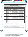
PROTECTIVE CLOTHING AND PERSONAL PROTECTIVE EQUIPMENT (PPE)
TABLE 130.7 (C) (16) FROM NFPA 70E 2015
Note below that this new PPE category table no longer references a category 0.
PPE
Category*
Clothing
Min.
APTV
Rating Cal/
cm
2
Required
Garments
Required Protective
Equipment
1
Arc-rated
clothing
1
and
PPE
4
Long-sleeve shirt and pants or
coverall. Flash suit hood or face
shield
2
. Jacket, parka, rainwear or
hard hat liner (AN).
Hard hat.
Safety glasses or
safety goggles (SR). Hearing
protection (ear canal inserts).
Heavy duty leather gloves
3
.
Leather footwear (AN).
2
Arc-rated
clothing
1
and
PPE
8
Long-sleeve shirt and pants or
coverall. Flash suit hood or face
shield
2
and balaclava. Jacket, parka,
rainwear or hard hat liner (AN).
Hard hat.
Safety glasses or
safety goggles (SR). Hearing
protection (ear canal inserts).
Heavy duty leather gloves
3
.
Leather footwear (AN).
3
Arc-rated
clothing
system
1
and PPE
25
Long sleeve shirt (AR). Pants (AR).
Coverall (AR). Flash suit jacket
(AR). Flash suit pants (AR). Flash
suit hood. Gloves
1
. Jacket, parka,
rainwear or hard hat liner (AN).
Hard hat.
Safety glasses or
safety goggles (SR). Hearing
protection (ear canal inserts).
Leather footwear (AN).
4
Arc-rated
clothing
system
3
and PPE
40
Long sleeve shirt (AR). Pants (AR)
.
Coverall (AR). Flash suit jacket
(AR). Flash suit pants (AR). Flash
suit hood. Gloves
1
. Jacket, parka,
rainwear or hard hat liner (AN).
Hard hat.
Safety glasses or
safety goggles (SR). Hearing
protection (ear canal inserts).
Leather footwear (AN).
AN = as needed (optional) AR = as required SR = selection required
One of the 3 basic methods is used to determine an HRC for a job task.
Arc rating is defined in article 100 NFPA 70E 2015 Edition.
Face shields are to have wrap-around guarding to protect not only the face but also the
forehead, ears and neck, or alternatively, an arc-rated flash suit hood is required to be worn.
If rubber insulating gloves with leather protectors are used, additional leather or arc-rated
gloves are not required. The combination of rubber insulating gloves with leather protectors
satisfies the arc flash protection requirement.
3
2
1
*
HVNCVT2-1390108ART.indd 10 7/20/2015 3:25:29 PM

11
Dwg Name: HVNCVT-2-1390108ART Dwg No: 1390107
ECO No: 19485 Pkg Dwg Ref: 1290179 Rev: A
Color Reference: CEN-PACK-003-A
Dwg Name: HVNCVT-2-1390108ART Dwg No: 1390107
ECO No: 19485 Pkg Dwg Ref: 1290179 Rev: A
Color Reference: CEN-PACK-003-A
CLEANING
Be sure tester is turned off and wipe with a clean, dry lint-free cloth.
Do not
use abrasive cleaners or solvents.
STORAGE
If the tester is not to be used for periods of longer than 60 days, remove the
batteries and store separately from the tester.
WARRANTY
www.kleintools.com/warranty
DISPOSAL / RECYCLE
Do not place equipment and its accessories in the trash. Items must be
properly disposed of in accordance with local regulations.
Please see www.epa.gov or www.erecycle.org for additional information.
CUSTOMER SERVICE
KLEIN TOOLS, INC.
450 Bond Street
Lincolnshire, IL 60069
www.kleintools.com
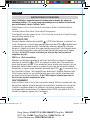
MAINTENANCE
BATTERY REPLACEMENT
1. Unscrew the tester handle (battery compartment) from the tester head.
2. Remove the 3 batteries.
3. Replace with 3 new batteries (1.5V “C” type). Batteries should be placed in the
handle with the negative (-) end down into the handle first, and the positive (+)
end upwards towards the head.
4. Screw the handle and head back together, ensuring that the black rubber O-ring
is still in place, taking care not to damage the O-ring.
HVNCVT2-1390108ART.indd 11 7/20/2015 3:25:29 PM

Dwg Name: HVNCVT-2-1390108ART Dwg No: 1390107
ECO No: 19485 Pkg Dwg Ref: 1290179 Rev: A
Color Reference: CEN-PACK-003-A
KLEIN TOOLS, INC. 450 Bond Street Lincolnshire, IL 60069 USA
[email protected] www.kleintools.com
HVNCVT2-1390108ART.indd 12 7/20/2015 3:25:29 PM

Dwg Name: HVNCVT-2-1390108ART Dwg No: 1390107
ECO No: 19485 Pkg Dwg Ref: 1290179 Rev: A
Color Reference: CEN-PACK-003-A
Dwg Name: HVNCVT-2-1390108ART Dwg No: 1390107
ECO No: 19485 Pkg Dwg Ref: 1290179 Rev: A
Color Reference: CEN-PACK-003-A
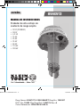
MANUAL DE INSTRUCCIONES
ESPAÑOL
HVNCVT2
Probador de alto voltaje sin
contacto de rango amplio
• TEST (PROBAR)
• 240V
• 4,2 kV
• 15 kV
• 25 kV
• 35 kV
• 69 kV
• 115 kV
• 230 kV
HVNCVT2-1390108ART.indd 13 7/20/2015 3:25:30 PM

14
Dwg Name: HVNCVT-2-1390108ART Dwg No: 1390107
ECO No: 19485 Pkg Dwg Ref: 1290179 Rev: A
Color Reference: CEN-PACK-003-A
SÍMBOLOS
Advertencia o precaución
Riesgo de choque eléctrico
Doble aislamiento
ESPECIFICACIONES GENERALES
El probador de alto voltaje sin contacto de rango amplio (HVNCVT2) es un instrumento
que sirve para verificar el estado activo o desenergizado de conductores y otros equipos
eléctricos expuestos. El probador advierte sobre la presencia de voltaje peligroso en varios
rangos diferentes, sin necesidad de hacer contacto con el conductor energizado. Solamente
utilice el probador con pértigas de trabajo en línea viva y guantes de goma que cumplan con
las normas de la industria. Revise la configuración del interruptor giratorio antes de medir
el voltaje para asegurarse de que sea la correcta para su aplicación.
Siempre respete las prácticas y distancias de trabajo seguro estipuladas en las Subpartes
R y V de la OSHA, además de todas las reglas de trabajo de la empresa. Para conocer las
distancias mínimas de proximidad, consulte las Tablas R-6 y R-7 de la OSHA (páginas 8 y
9) en este manual.
• Temperatura de operación: 14°F a 122°F (-10°C a 50°C) a 85% de humedad relativa
• Temperatura de almacenamiento: -4°F a 140 °F (-20°C a 60 °C) a 85% de humedad
relativa
• Dimensiones: Probador: 10" × 4,25" × 4,25" (254mm × 108mm × 108 mm)
Estuche: 13,5" × 8,75" × 4,75" (343mm × 222mm × 121mm)
• Peso: 1,32lb (600g)
• Fuente de energía: Tres baterías de celda tipo "C" de 1,5V
Especificaciones sujetas a cambios.
ESPAÑOL
HVNCVT2-1390108ART.indd 14 7/20/2015 3:25:30 PM

15
Dwg Name: HVNCVT-2-1390108ART Dwg No: 1390107
ECO No: 19485 Pkg Dwg Ref: 1290179 Rev: A
Color Reference: CEN-PACK-003-A
Dwg Name: HVNCVT-2-1390108ART Dwg No: 1390107
ECO No: 19485 Pkg Dwg Ref: 1290179 Rev: A
Color Reference: CEN-PACK-003-A
ADVERTENCIAS
Para garantizar un funcionamiento y servicio seguros del probador, siga estas instrucciones.
El incumplimiento de estas advertencias puede provocar lesiones graves o la muerte.
• Tenga mucho cuidado cuando trabaje con circuitos eléctricos activos porque
podría sufrir lesiones por choque eléctrico.
• Siempre utilice el probador con pértigas de trabajo en línea viva y guantes de goma que
cumplan con las normas de la industria.
• Respete las prácticas y distancias de trabajo seguro estipuladas en las Subpartes R y V
de la OSHA, además de todas las reglas de trabajo de la empresa.
• Siempre realice pruebas en un circuito activo para verificar que el probador funciona
antes de usarlo.
• No supere los límites que se indican en el instrumento. Nunca realice pruebas de voltaje
de más de 230kV CA RMS.
• Al efectuar mediciones, no permita que su cuerpo quede conectado a tierra o a masa.
Notoque elementos de circuitos expuestos.
• Cumpla con las medidas de seguridad pertinentes si trabaja con voltajes superiores a
30V CA RMS para evitar riesgos de choque eléctrico.
• No suponga que los equipos o conductores están o permanecerán desenergizados.
Siempre instale dispositivos de puesta a tierra adecuados antes de iniciar el procedimiento.
• No haga funcionar el probador en una atmósfera explosiva.
• No exponga el probador a la lluvia ni a la humedad. Esto aumenta el riesgo de incendio
o choque eléctrico.
• Este probador no es seguro para utilizar con cable blindado o cable neutro concéntrico.
• No permita que la unidad entre en contacto con el voltaje de líneas vivas. No toque
ningún cable, conexión o pieza energizada expuesta de un circuito eléctrico.
• Los cables de alimentación trifásicos que poseen conductores en mutua proximidad
pueden autoanular el campo eléctrico y no ser detectados por el dispositivo. Verifique
que los conductores de fase tengan una separación mínima de 15" (381mm) antes de
realizar la prueba de voltaje de CA.
• No utilice el probador en áreas donde haya altos voltajes mezclados. Ante la presencia
devoltajes mixtos, las mediciones del probador pueden ser poco confiables.
• Siempre asegúrese de ubicar el probador directamente debajo del conductor que
probará. En caso de existir otros voltajes activos en las proximidades, el probador
podríadetectar esos voltajes adyacentes.
HVNCVT2-1390108ART.indd 15 7/20/2015 3:25:31 PM

16
Dwg Name: HVNCVT-2-1390108ART Dwg No: 1390107
ECO No: 19485 Pkg Dwg Ref: 1290179 Rev: A
Color Reference: CEN-PACK-003-A
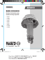
1. LED indicadores de voltaje
2. Zumbador
3. Compartimento de baterías
4. Punto de conexión de la pértiga
de trabajo en línea viva
5. Selector de sensibilidad:
• OFF (Apagado)
• TEST (Probar)
• 240V
• 4,2 kV
• 15 kV
• 25 kV
• 35 kV
• 69 kV
• 115 kV
• 230 kV
DETALLES DE LAS CARACTERÍSTICAS
ESPAÑOL
3
2
4
5
1 1
1
HVNCVT2-1390108ART.indd 16 7/20/2015 3:25:31 PM

17
Dwg Name: HVNCVT-2-1390108ART Dwg No: 1390107
ECO No: 19485 Pkg Dwg Ref: 1290179 Rev: A
Color Reference: CEN-PACK-003-A
Dwg Name: HVNCVT-2-1390108ART Dwg No: 1390107
ECO No: 19485 Pkg Dwg Ref: 1290179 Rev: A
Color Reference: CEN-PACK-003-A
INSTRUCCIONES DE OPERACIÓN
SOLO PARA USO POR PARTE DE PERSONAL CAPACITADO
Todas las personas que utilicen este instrumento deben estar informadas y
capacitadas respecto de los riesgos que supone medir voltajes de medio y alto
rango. También deben comprender la importancia de tomar medidas de seguridad
y de probar el instrumento antes y después de usarlo para asegurarse de que está
en buenas condiciones de funcionamiento.
EJEMPLOS DE USO:
• Detección sin contacto de voltaje de CA activo
• Búsqueda de fallas en cables
• Verificación y detección de cables de circuito vivo con alto voltaje
• Rastreo de cables con corriente
• Verificación de equipos de puesta a tierra
VG
90°
PÉRTIGA DE TRABAJO
EN LÍNEA VIVA
PÉRTIGA DE TRABAJO
EN LÍNEA VIVA
Fig.1: Ángulo óptimo
dedetección
Fig.2: Búsqueda de una
falla en el cable
Fig.3: Detección de voltaje
en líneas aéreas
HVNCVT2-1390108ART.indd 17 7/20/2015 3:25:32 PM

18
Dwg Name: HVNCVT-2-1390108ART Dwg No: 1390107
ECO No: 19485 Pkg Dwg Ref: 1290179 Rev: A
Color Reference: CEN-PACK-003-A
ESPA
ÑOL
INSTRUCCIONES DE OPERACIÓN
Antes de cada uso, verique que el probador no presente signos visibles de
daño. Si el probador está dañado o no funciona correctamente, discontinúe
su uso.
Siempre realice una prueba en un circuito activo para verificar que el probador
funciona. El probador debe utilizarse como indicador solamente.
El probador siempre debe estar limpio y seco. De lo contrario, límpielo con un paño
limpio, seco, que no deje pelusas.
FUNCIÓN DE PRUEBA
Gire la perilla del selector de sensibilidad
5
a la posición TEST (PROBAR) para
realizar una autoprueba en la unidad. Observe una luz roja fija en los tres LED
1
y escuche el indicador sonoro constante agudo. Esta función de autoprueba
confirma la carga suficiente de la batería, la integridad del sistema y el modo de
funcionamiento/activo. Siempre realice pruebas en circuitos activos para verificar
que el probador funciona antes de usarlo.
Si los tres LED rojos no se encienden
y el indicador sonoro no se oye, reemplace las baterías.
240V CA (prueba auxiliar)
Realice una segunda prueba antes de usar el probador girando la perilla del selector
de sensibilidad
5
a la posición de 240V y ubicando el extremo del instrumento
cerca de un conductor activo de bajo voltaje. Si no hay disponible un conductor
vivo de bajo voltaje, frote el extremo del probador contra la ropa para generar
corriente estática. Observe una luz roja parpadeante en los tres LED
1
y escuche
el indicador sonoro constante. Consulte la Figura 1 de la página 17 para conocer
el ángulo óptimo de detección. Siempre realice pruebas en circuitos activos para
verificar que el probador funciona antes de usarlo.
Si los tres LED rojos no se
encienden y el indicador sonoro no se oye, reemplace las baterías.
OPERACIÓN
Antes de usar la unidad, es necesario conectar una pértiga de trabajo en línea
viva. Solamente utilice el probador con pértigas de trabajo en línea viva y
guantes de goma que cumplan con las normas de la industria. Siempre respete
las prácticas y distancias de trabajo seguro estipuladas en las Subpartes R y V
delaOSHA, además de todas las reglas de trabajo de la empresa.
HVNCVT2-1390108ART.indd 18 7/20/2015 3:25:32 PM

19
Dwg Name: HVNCVT-2-1390108ART Dwg No: 1390107
ECO No: 19485 Pkg Dwg Ref: 1290179 Rev: A
Color Reference: CEN-PACK-003-A
Dwg Name: HVNCVT-2-1390108ART Dwg No: 1390107
ECO No: 19485 Pkg Dwg Ref: 1290179 Rev: A
Color Reference: CEN-PACK-003-A
INSTRUCCIONES DE OPERACIÓN
Gire la perilla del selector de sensibilidad
5
al ajuste adecuado. Se recomienda
comenzar con un ajuste de prueba menor que el voltaje de trabajo real, y luego ir
aumentando el valor gradualmente hasta que el instrumento detecte el voltaje.
Mueva el probador lentamente hacia el conductor activo hasta que se dispare la
señal de advertencia. Consulte la Fig. 1 de la página 17 para conocer el ángulo
óptimo de detección. Siempre mantenga la distancia mínima de proximidad
especificada en las Tablas R-6 y R-7 de la OSHA, que se encuentran en las
páginas 20 y 21 de este manual.
BÚSQUEDA DE FALLAS EN CABLES
El probador puede utilizarse para buscar fallas en algunos cables flexibles. Gire la
perilla del selector de sensibilidad
5
a la posición correspondiente al voltaje del cable
energizado que se pretende detectar. Mueva el detector a lo largo del cable (pero no lo
toque), y observe si oye un indicador sonoro rápido o constante y si ve las tres luces
LED rojas
1
parpadeando rápidamente o fijas. Al llegar al lugar de la falla, la unidad
deja de sonar y las luces dejan de parpadear. Consulte la Fig. 2 en la página 17. Siempre
mantenga la distancia mínima de proximidad especificada en las Tablas R-6 y R-7 de la
OSHA, que se encuentran en las páginas 20 y 21 de este manual.
HVNCVT2-1390108ART.indd 19 7/20/2015 3:25:32 PM

20
Dwg Name: HVNCVT-2-1390108ART Dwg No: 1390107
ECO No: 19485 Pkg Dwg Ref: 1290179 Rev: A
Color Reference: CEN-PACK-003-A
ESPAÑOL
TABLA R-6: DISTANCIAS MÍNIMAS DE PROXIMIDAD ALTERNATIVAS PARA
VOLTAJES IGUALES O MENORES QUE 72,5kV
1
Voltaje nominal
(kV)
entre fases
Distancia
Exposición entre fase y tierra
Exposición entre fases
pies m pies m
0,50 a 0,300
2
Evitar
el contacto
Evitar
el contacto
Evitar
el contacto
Evitar
el contacto
0,301 a 0,750
2
1,09 0,33 1,09 0,33
0,751 a 5,0 2,07 0,63 2,07 0,63
5,1 a 15,0 2,14 0,65 2,24 0,68
15,1 a 36,0 2,53 0,77 2,92 0,89
36,1 a 46,0 2,76 0,84 3,22 0,98
46,1 a 72,5 3,29 1,00 3,94 1,20
Los empleadores pueden utilizar las distancias mínimas de proximidad especificadas en esta
tabla siempre que el lugar de trabajo se encuentre a una altura de 3.000pies (900metros)
o menos. En caso de que los empleados deban trabajar a una altura mayor que 3.000pies
(900metros) sobre el nivel medio del mar, el empleador deberá determinar las distancias
mínimas de proximidad multiplicando las distancias especificadas en esta tabla por el factor
de corrección de la Tabla R-5: Factor de corrección de altura de la OSHA, que corresponda a
la altura de trabajo.
Para sistemas monofásicos, use voltaje a tierra.
INSTRUCCIONES DE OPERACIÓN
Siempre respete las prácticas y distancias de trabajo seguro estipuladas en
las Subpartes R y V de la OSHA, además de todas las reglas de trabajo de la
empresa.
Para conocer las distancias mínimas de proximidad, consulte las Tablas R-6 y
R-7 de la OSHA a continuación.
1
2
HVNCVT2-1390108ART.indd 20 7/20/2015 3:25:32 PM
La page est en cours de chargement...
La page est en cours de chargement...
La page est en cours de chargement...
La page est en cours de chargement...
La page est en cours de chargement...
La page est en cours de chargement...
La page est en cours de chargement...
La page est en cours de chargement...
La page est en cours de chargement...
La page est en cours de chargement...
La page est en cours de chargement...
La page est en cours de chargement...
La page est en cours de chargement...
La page est en cours de chargement...
La page est en cours de chargement...
La page est en cours de chargement...
-
 1
1
-
 2
2
-
 3
3
-
 4
4
-
 5
5
-
 6
6
-
 7
7
-
 8
8
-
 9
9
-
 10
10
-
 11
11
-
 12
12
-
 13
13
-
 14
14
-
 15
15
-
 16
16
-
 17
17
-
 18
18
-
 19
19
-
 20
20
-
 21
21
-
 22
22
-
 23
23
-
 24
24
-
 25
25
-
 26
26
-
 27
27
-
 28
28
-
 29
29
-
 30
30
-
 31
31
-
 32
32
-
 33
33
-
 34
34
-
 35
35
-
 36
36


dans d''autres langues
Documents connexes
-
Klein Tools HVNCVT-1 Mode d'emploi
-
-
-
-
-
-
Klein Tools VDV026-813 Mode d'emploi
-
Klein Tools ET120 Manuel utilisateur
-
-