Ingersoll Rand SS3 Le manuel du propriétaire
- Catégorie
- Compresseurs d'air
- Taper
- Le manuel du propriétaire
Ce manuel convient également à

22204911
Revision D
April 2018
Save These Instructions
Reciprocating Air Compressors
Engine Driven Wheelbarrow SS3
Owner’s Manual with Parts List
Owner’s Manual with Parts List
EN
Manual del propietario con la lista de piezas
Manuel du propriétaire avec liste des pièces
FR
ES
RELEASED 16/Apr/2018 18:50:16 GMT
PRINT LANGUAGE
ENGLISH
SPANISH
FRENCH

EN
EN-2 22204911 Rev. D
CONSUMER INFORMATION SHEET. . . . . . . . . . . . . . . . . . . . . 3
INSTALLATION, OPERATION, MAINTENANCE &
TROUBLESHOOTING ISSUES ............................3
MISSING PARTS .........................................3
SHIPPING DAMAGE OR DEFECTIVE PARTS ...............3
ABOUT THIS MANUAL . . . . . . . . . . . . . . . . . . . . . . . . . . . . . . . . 4
SAFETY INFORMATION . . . . . . . . . . . . . . . . . . . . . . . . . . . . . . . 4
EXPLANATION OF SAFETY SIGNAL WORDS ..............4
GENERAL SAFETY PRECAUTIONS .......................4
ADDITIONAL GENERAL SAFETY PRECAUTIONS ..........5
GENERAL INFORMATION. . . . . . . . . . . . . . . . . . . . . . . . . . . . . . 5
INSTALLATION . . . . . . . . . . . . . . . . . . . . . . . . . . . . . . . . . . . . . . . 6
SELECTING A LOCATION ................................6
GENERAL . . . . . . . . . . . . . . . . . . . . . . . . . . . . . . . . . . . . . . . . . . . .6
TEMPERATURE . . . . . . . . . . . . . . . . . . . . . . . . . . . . . . . . . . . . . . .6
HUMID AREAS . . . . . . . . . . . . . . . . . . . . . . . . . . . . . . . . . . . . . . .6
NOISE CONSIDERATIONS . . . . . . . . . . . . . . . . . . . . . . . . . . . .6
INSTALLING THE ISOLATOR PADS .......................6
INSTALLING THE INLET AIR FILTER .......................6
INSTALLING DISCHARGE PIPING ........................6
SYNTHETIC COMPRESSOR LUBRICANT MATERIAL
COMPATIBILITY LIST . . . . . . . . . . . . . . . . . . . . . . . . . . . . . . . . .7
GENERAL REQUIREMENTS . . . . . . . . . . . . . . . . . . . . . . . . . . .7
CONDENSATE DISCHARGE PIPING . . . . . . . . . . . . . . . . . . .7
COMPRESSOR LUBRICATION ............................8
SYNTHETIC COMPRESSOR LUBRICANT . . . . . . . . . . . . . . .8
ALTERNATE LUBRICANTS. . . . . . . . . . . . . . . . . . . . . . . . . . . . .8
COMPRESSOR PUMP FILLING PROCEDURES. . . . . . . . . .8
ENGINE LUBRICATION AND FUEL. . . . . . . . . . . . . . . . . . . . .8
OPERATION . . . . . . . . . . . . . . . . . . . . . . . . . . . . . . . . . . . . . . . . . . 9
GENERAL ...............................................9
NORMAL STARTUP ....................................9
STARTUP. . . . . . . . . . . . . . . . . . . . . . . . . . . . . . . . . . . . . . . . . . . .9
SHUTDOWN . . . . . . . . . . . . . . . . . . . . . . . . . . . . . . . . . . . . . . . . .9
MAINTENANCE . . . . . . . . . . . . . . . . . . . . . . . . . . . . . . . . . . . . . . 10
FILTER REPLACEMENT .................................10
COMPRESSOR PUMP OIL CHANGE .....................10
TROUBLESHOOTING. . . . . . . . . . . . . . . . . . . . . . . . . . . . . . . . . 11
SS3 BARE COMPRESSOR PUMP ASSEMBLY. . . . . . . . . . . . 12
MODEL SS3 BARE COMPRESSOR PUMP ................12
SS3 COMPRESSOR PARTS LIST . . . . . . . . . . . . . . . . . . . . . . . 14
KITS & ACCESSORIES. . . . . . . . . . . . . . . . . . . . . . . . . . . . . . . . . 16
EXTENDED WARRANTY KIT ............................16
INGERSOLLRAND SYNTHETIC COMPRESSOR ............
LUBRICANT ............................................16
AIR FILTER ELEMENT ...................................16
STEP SAVER KITS .......................................16
CRANKCASE HEATER KIT ...............................16
MULTIPURPOSE AIR HOSES ...........................16
ENGINE PARTS .........................................16
WARRANTY AND LIMITATION OF LIABILITY . . . . . . . . . . . 17
WARRANTY ............................................17
LIMITATION OF LIABILITY ..............................17
CONTENTS
RELEASED 16/Apr/2018 18:50:16 GMT

22204911 Rev. D EN-3
EN
CONSUMER INFORMATION SHEET
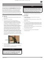
Thank you for purchasing an Ingersoll Rand product. We trust that it will oer you many years of trouble-free service. If you
encounter any problems or need assistance, please refer to the information provided in this sheet.
INSTALLATION, OPERATION, MAINTENANCE & TROUBLESHOOTING ISSUES
Read the owner’s manual rst. Often this will clarify your understanding. If you still have problems, please call the toll-free
hotline.
MISSING PARTS
If parts are missing call the toll-free hotline. Have the serial number, part number, model number and parts list (with missing
parts circled) handy when you call. Your parts will be shipped immediately.
SHIPPING DAMAGE OR DEFECTIVE PARTS
Each new product is inspected and in good condition prior to shipment from the factory. If your product was received in a
condition that was less than satifactory, or if you discover a defect that require service or adjustment by qualied personnel,
please contact your nearest authorized service representative.
DO NOT RETURN THE PRODUCT TO YOUR RETAILER!
PARTS & SERVICE HOTLINE:
1-800-AIR-SERV
(1-800-247-7378)
RELEASED 16/Apr/2018 18:50:16 GMT

EN
EN-4 22204911 Rev. D
This manual provides safe and reliable instructions for the installation, operation and maintenance of your Ingersoll Rand air
compressor. Carefully read this manual before attempting to operate or perform any maintenance. If you are uncertain about
any of the instructions or procedures provided in this manual, contact Ingersoll Rand. We recommend you retain this manual,
and all publications provided with your air compressor, in a location which is accessible to all personnel who operate and
service your compressed air equipment.
ABOUT THIS MANUAL
SAFETY INFORMATION
EXPLANATION OF SAFETY SIGNAL WORDS
Throughout this manual there are steps and procedures,
which if not followed may result in a hazard. The following
signal words are used to identify the level of potential hazard.
DANGER
Indicates an imminently
hazardous situation, which if not
avoided will result in death or
serious injury.
WARNING
Indicates a potentially hazardous
situation, which if not avoided
could result in death or serious
injury.
CAUTION
Indicates a potentially hazardous
situation, which if not avoided
may result in minor or moderate
injury or property damage.
NOTICE
Indicates information or a
company policy that relates
directly or indirectly to the safety
of personnel or protection of
property.
GENERAL SAFETY PRECAUTIONS
DANGER
INTAKE AIR
Can contain carbon monoxide or other contaminants.
Will cause serious injury or death. Ingersoll Rand air
compressors are not designed, intended or approved
for breathing air. Compressed air should not be used for
breathing air applications unless treated in accordance
with all applicable codes and regulations.
WARNING
HAZARDOUS VOLTAGE
Can cause serious injury or death. Disconnect power
and bleed pressure from the tank before servicing.
Lockout/Tagout machine. Compressor must be
connected to properly grounded circuit. See grounding
instructions in manual. Do not operate compressor in
wet conditions. Store indoors.
WARNING
MOVING PARTS
Can cause serious injury. Do not operate with guards
removed. Machine may start automatically. Disconnect
power before servicing. Lockout/Tagout machine.
WARNING
HOT SURFACES.
Can cause serious injury. Do not touch. Allow to cool
before servicing. Do not touch hot compressor or
tubing.
WARNING
HIGH PRESSURE AIR.
Bypassing, modifying or removing safety/relief valves
can cause serious injury or death. Do not bypass,
modify or remove safety/relief valves. Do not direct air
stream at body. Rusted tanks can cause explosion and
severe injury or death. Drain tank daily or after each
use. Drain valve located at bottom of tank.
CAUTION
RISK OF BURSTING
Use only suitable air handling parts acceptable for
pressure of not less than the maximum allowable
working pressure of the machine.
RELEASED 16/Apr/2018 18:50:16 GMT

22204911 Rev. D EN-5
EN
ADDITIONAL GENERAL SAFETY PRECAUTIONS
• Compressor must be operated in well-ventilated area.
• Do not directly inhale compressed air.
• Do not over pressurize the receiver tank or similar vessel
beyond design limits.
• Do not use a receiver tank or similar vessels that fail to
meet the design requirements of the compressor. For
additional information contact the Ingersoll Rand factory
or the nearest service provider.
• Do not drill into, weld or otherwise alter the receiver tank
or similar vessels.
• Do not remove, adjust, bypass, change, modify or make
substitutions for safety/relief valves or other pressure
control related devices.
• Do not use air tools or attachments without rst
determining the maximum pressure recommended for
that equipment.
• Do not point air nozzles toward anyone.
• Do not touch the compressor pump, engine or discharge
tubing during or shortly after operation. These parts
become hot.
• Wear eye protection when operating or servicing
compressor.
• Do not operate where ammable or explosive liquids
or vapors such as gasoline, natural gas and solvents are
present.
• Do not operate with guards or shields removed, damaged
or broken.
• Do not remove, paint over or deface decals. Replace any
missing decals.
The air compressor unit is suitable for operating a variety
of air tools. Depending on your application, the following
accessories may be required:
• An air line lter for removal of moisture and oil vapor in
compressed air.
• An in-line lubricator to prolong the life of air tools.
• Separate air transformers which combine the functions of
air regulation and/or moisture and dirt removal.
Contact your nearest authorized dealer for more information
on air tools and accessories for your application.
SAFETY INFORMATION
GENERAL INFORMATION
RELEASED 16/Apr/2018 18:50:16 GMT

EN
EN-6 22204911 Rev. D
SELECTING A LOCATION
GENERAL
Select a clean, dry, well-lighted area with plenty of ventilation
proper cooling air ow and accessibility. Locate the unit at
least 12 inches (30 cm) from walls. Ensure that the unit is as
level as possible to avoid fuel spillage.
TEMPERATURE
Ideal operating temperatures are between
40 °F to 100 °F (4 °C to 37.8 °C). In lower temperatures, you
must protect safety/relief valves and drain valves from
freezing.
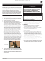
HUMID AREAS
In frequently humid areas, moisture may form in the bare
pump and produce sludge in the lubricant, causing running
parts to wear out prematurely. Excessive moisture is especially
likely to occur if the unit is located in an unheated area
that is subjected to large temperature changes. Two signs
of excessive humidity are external condensation on the
bare pump when it cools down and a “milky” appearance in
petroleum compressor lubricant. You may be able to prevent
moisture from forming in the bare pump by increasing
ventilation or operating for longer intervals.
NOISE CONSIDERATIONS
Consult local ocials for information regarding acceptable
noise levels in your area. To reduce excessive noise, use
vibration mounts or intake silencers, relocate the unit or bae
walls. Consult your dealer for assistance.
INSTALLING THE ISOLATOR PADS
1. Install isolator pads (A) on all four feet with self-tap
screws (B).
2. Hand tighten screws.
INSTALLING THE INLET AIR FILTER
CAUTION
Do not operate without air inlet lter.
Install the air inlet lter at the inlet connection at the bare
pump. If heavy duty ltration is required, contact your dealer
for information.
INSTALLING DISCHARGE PIPING
If it is necessary to install air discharge piping or condensate
discharge piping, adhere to the following general guidelines.
Contact your dealer for more information.
WARNING
Do not use plastic pipe, rubber hose or lead-tin
soldered joints anywhere in the compressed air
system.
WARNING
If an after-cooler, check valve, block valve, or any
other restriction is added to the compressor discharge,
install a properly-sized ASME approved safety/relief
valve between the compressor discharge and the
restriction.
CAUTION
If you will be using Ingersoll Rand Synthetic
Lubricant all downstream piping material and
system components must be compatible. Refer to the
following compatibility list. If there are incompatible
materials present in your system, or there are
materials not included in the list, contact your dealer.
INSTALLATION
RELEASED 16/Apr/2018 18:50:16 GMT

22204911 Rev. D EN-7
EN
SYNTHETIC COMPRESSOR LUBRICANT MATERIAL COMPATIBILITY LIST
SUITABLE NOT RECOMMENDED
•Viton® •Neoprene
•Teon® •Natural Rubber
•Epoxy (Glass Filled) •SBR Rubber
•Oil Resistant Alkyd •Acrylic Paint
•Fluorosilicone •Lacquer
•Fluorocarbon •Varnish
•Polysulde •Polystyrene
•2-Component Urethane •PVC
•Nylon •ABS
•Delrin® •Polycarbonate
•Celcon® •Cellulose Acetate
•High Nitrile Rubber (Buna N. NBR more than 36%
Acrylonitrile)
•Low Nitrile Rubber (Buna N. NBR less than 36%
Acrylonitrile)
•Polyurethane •EPDM
•Polyethylene •Ethylene Vinyl Acetate
•Epichlorohydrin •Latex
•Polyacrylate •EPR
•Melamine •Acrylics
•Polypropylene •Phenoxy
•Baked Phenolics •Polysulfones
•Epoxy •Styrene Acrylonitrile (San)
•Modied Alkyds (® indicates trademark of DuPont
Corporation).
•Butyl.
INSTALLATION
GENERAL REQUIREMENTS
The piping, ttings, air receiver tank, etc. must be certied
safe for at least the maximum working pressure of the unit.
Use hard-welded or threaded steel or copper pipes and cast
iron ttings and hoses that are certied safe for the unit’s
discharge pressure and temperature. DO NOT USE PVC
PLASTIC. Use pipe thread sealant on all threads, and make up
joints tightly to prevent air leaks.
CONDENSATE DISCHARGE PIPING
If installing a condensate discharge line, the piping must be at
least one size larger than the connection, as short and direct
as possible, secured tightly and routed to a suitable drain
point or waste container. Condensate must be disposed of in
accordance with local, state, and federal laws and regulations.
NOTICE
All compressed air systems generate condensate,
which accumulates in any drain point (e.g. tanks,
lters, drip legs, after-coolers, dryers). This condensate
contains lubricating oil and/or substances, which may
be regulated and must be disposed of in accordance
with local, state, and federal laws and regulations.
RELEASED 16/Apr/2018 18:50:16 GMT

EN
EN-8 22204911 Rev. D
COMPRESSOR LUBRICATION
CA
UTION
Do not operate without lubricant or with inadequate
lubricant. Ingersoll Rand is not responsible for
compressor failure caused by inadequate lubrication.
SYNTHETIC COMPRESSOR LUBRICANT
Ingersoll Rand recommends All Season Select synthetic
lubricant from start-up. See the WARRANTY section for
extended warranty information.
ALTERNATE LUBRICANTS
You may use XL-300 or a comparable petroleum-based
lubricant that is premium quality, does not contain
detergents, contains only anti-rust, anti-oxidation, and anti-
foam agents as additives, has a ashpoint of 440°F (227°C)
or higher, and has an auto-ignition point of 650°F (343°C) or
higher.
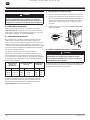
See the petroleum lubricant viscosity table below. The table
is intended as a general guide only. Heavy duty operating
conditions require heavier viscosities. Refer specic operating
conditions to Ingersoll Rand for recommendations.
Temperature
Around
Compressor
Viscosity @ 100°F
(37.8°C) Viscosity
Grade
°F °C SUS Centistokes ISO SAE
< 40 < 4.4 150 32 32 10
40-80 4.4-26.7 500 110 100 30
80-125 26.7-51.0 750 165 150 40
If you use a petroleum-based compressor lubricant at start-
up and decide to convert to All Season Select later on, the
pump must be decarbonized and ushed before conversion.
Contact Ingersoll Rand for more information.
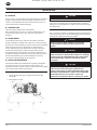
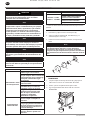
COMPRESSOR PUMP FILLING PROCEDURES
1. Unscrew and remove the oil ll plug (A).
2. Slowly ll the crankcase with lubricant until the lubricant
reaches the bottom thread of the oil ll opening and the
top of the sight glass.
Note: SS3 Crankcase capacity is one (1) pint (0.5 liters).
3. Replace the oil ll plug HAND TIGHT ONLY.
A
Add
Full
ENGINE LUBRICATION AND FUEL
CAUTION
Do not operate without lubricant or with inadequate
lubricant. Ingersoll Rand is not responsible for engine
failure caused by inadequate lubrication.
Refer to the engine operator’s manual provided with the unit
for engine lubrication and fuel requirements.
INSTALLATION
RELEASED 16/Apr/2018 18:50:16 GMT

22204911 Rev. D EN-9
EN
OPERATION
GENERAL
The air compressor is designed for 100% continuous duty
operation with the use of Ingersoll Rand all season select
synthetic lubricant and 60% continuous duty operation with
the use of petroleum lubricant. In other words, synthetic
lubricant allows the compressor to pump continuously
without cycling. Petroleum lubricant limits the compressor
to a maximum of 36 minutes of pumping time per hour. The
compressor should not cycle more than 10 times per hour.
NORMAL START-UP
START-UP
1. Turn regulator adjusting knob counter-clockwise until
fully closed.
2. Attach hose and accessory.
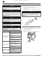
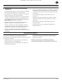
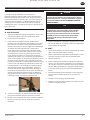
3. This compressor package is equipped with an
automatic unloader valve assembly eliminating the
need to manually toggle the valve for engine starting.
In addition, the automatic unloader has a “Cold Start”
feature shown in the illustration below. This valve
bleeds air from the compressor discharge airstream
during engine starting, reducing engine starting torque
requirements. These valves are especially helpful on
oil-lubed compressor pumps that may be subject to
low temperatures. When the discharge line is at zero
pressure, the Cold Start valve is open. As the engine
starts, air ows out of the Cold Start bleed hole into the
atmosphere; as discharge pressure increases, the bleed
hole closes and stays closed until the end of the pump-
up cycle. During normal operation a negligible air ow
may be felt at the Cold Start bleed hole. This is not cause
for concern.
COLD START
BLEED HOLE
4. Follow instructions in engine owner’s manual for starting
and running engine.
5. Using the tank pressure gauge for reference, allow tank
pressure to build to maximum pressure.
CAUTION
Unusual noise or vibration indicates a problem. Do not
continue to operate until you identify and correct the
source of the problem. IF EMERGENCY CONDITIONS
ARE ENCOUNTERED, SHUT-OFF IMMEDIATELY.
NOTICE
When the tank reaches cut-out pressure, the
compressor stops pumping but the engine continues
to run. When the receiver tank pressure drops below
the factory pre-set minimum, the compressor resumes
pumping and the tank builds to cut-out pressure.
6. Turn regulator adjusting knob clockwise to obtain
desired pressure, indicated by the gauge mounted on
the regulator.
SHUTDOWN
1. Follow instructions in engine owner’s manual for
shutting o engine.
2. Turn regulator adjusting knob counter-clockwise until
fully closed.
3. Remove accessory.
4. Turn regulator adjusting knob clockwise slowly to allow
air to escape from tank. When the tank pressure gauge
indicates 20 psig, turn regulator adjusting knob counter-
clockwise until fully closed.
5. Open manual drain valve slowly to drain moisture from
tank and bleed remaining air.
6. Close manual drain valve.
7. Turn fuel shut-o valve to “o” position before
transporting unit.
RELEASED 16/Apr/2018 18:50:16 GMT

EN
EN-10 22204911 Rev. D
WARNING
Disconnect wire from engine spark plug and release
air pressure from the tank before performing
maintenance.
NOTICE
All compressed air systems contain maintenance
parts (e.g. lubricating oil, lters, separators) which are
periodically replaced. These used parts may be, or may
contain, substances that are regulated and must be
disposed of in accordance with local, state, and federal
laws and regulations.
NOTICE
Take note of the positions and locations of parts
during disassembly to make reassembly easier. The
assembly sequences and parts illustrated may dier
for your particular unit.
NOTICE
Follow engine owner’s manual for engine maintenance
schedules and procedures.
NOTICE
Any service operations not included in this section
should be performed by an authorized service
representatives.
PERIOD MAINTENANCE
Daily or before each
operation
Check lubricant level. Fill as needed.
Drain receiver tank condensate.
Open the manual drain valve
and collect, dispose condensate
accordingly.
Check for unusual noise and
vibration.
Ensure beltguards and covers are
securely placed.
Ensure area around compressor is
free from rags, tools, debris, and
ammable or explosive materials.
Weekly/Monthly
Inspect air lter element. Clean/
Replace if necessary.
Inspect for air leaks. Squirt soapy
water around joints during
compressor operation and watch for
bubbles.
Check tightness of screws and bolts.
Tighten as needed.
Petroleum - 3/500*
Synthetic - 12/2000*
Clean exterior.
Change petroleum lubricant while
crankcase is warm.
Change synthetic lubricant while
crankcase is warm.
Replace lter element.
* - indicates months/operating hours, whichever occurs rst
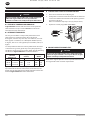
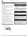
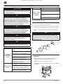
FILTER REPLACEMENT
1. Unscrew and remove the wing-nut (A).
2. Remove the lter cover (B), bae (C) and element (D)
from the base (E).
3. Install a new element and reassemble the lter assembly.
NOTICE
The air intake holes in the bae and cover must be
staggered 180°. When reinstalling the assembly at the
inlet connection, ensure the intake hole in the cover is
on the bottom to minimize the entry of foreign matter
from the air.
A
B
C
D
E
COMPRESSOR PUMP OIL CHANGE
1. Remove the oil drain plug (A) and allow the lubricant to
drain into a suitable container.
2. Replace the oil drain plug.
3. Follow the lling procedures in OPERATION section.
A
MAINTENANCE
RELEASED 16/Apr/2018 18:50:16 GMT

22204911 Rev. D EN-11
EN
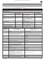
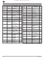
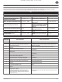
This section provides a list of the more frequently encountered malfunctions, their causes and corrective actions. Some
corrective actions can be performed by the operator or maintenance personnel, and others may require the assistance of a
qualied Ingersoll Rand technician or your dealer.
NOTICE
Please see engine owner’s manual for additional engine troubleshooting.
PROBLEM CHECK POINT PROBLEM CHECK POINT
Abnormal piston, ring or cylinder
wear 4, 7, 8, 14, 19, 26 High oil consumption 1, 4, 8, 13, 14, 15, 17, 22
Air delivery drops 1, 5, 6, 11, 13, 14, 20 Knocking or rattling 2, 11, 12, 14, 15, 16
Unit does not come up to speed 2, 6, 11, 16 Moisture in crankcase or “milky”
appearance in petroleum lubricant
or rusting in cylinders 8, 9
Unit is slow to come up to speed 6, 18, 21 Oil in discharge air (oil pumping) 4, 8, 13, 14, 22, 23
Unit runs excessively hot 3, 10, 11 Oil leakage from shaft seal 17
Excessive noise during operation 2, 6, 7, 11, 12, 16, 18 Safety/relief valve “pops” 1, 11, 20
Excessive starting and stopping 5, 18, 23
CHECK
POINTS POSSIBLE CAUSE POSSIBLE SOLUTION
1 Clogged or dirty inlet and/or discharge line lter. Clean or replace.
2Loose beltwheel or engine pulley, excessive end play
in engine shaft or loose drive belts. Check beltwheel, engine pulley, crankshaft, drive belt
tension and alignment. Repair or replace as required.
3 Inadequate ventilation around beltwheel. Relocate unit for better air ow.
4 Lubricant viscosity too low. Drain existing lubricant and rell with proper lubricant.
5 Air leaks in air discharge piping. Check tubing and connections.
6 Lubricant viscosity too high. Drain existing lubricant and rell with proper lubricant.
7 Lubricant level too low Add lubricant to crankcase to proper level.
8 Detergent type lubricant being used. Drain existing lubricant and rell with proper lubricant.
9Extremely light duty cycles.
Unit located in damp or humid location. Run unit for longer duty cycles.
Relocate unit.
10 Drive belts too tight or misaligned. Adjust belts to proper tension and alignment.
11 Compressor valves leaky, broken, carbonized or
loose. Inspect valves. Clean or replace as required.
12 Carbon build-up on top of piston(s). Clean piston(s). Repair or replace as required.
13
Piston rings damaged or worn (broken, rough or
scratched).
Excessive end gap or side clearance.
Piston rings not seated, are stuck in grooves or end
gaps not staggered.
Adjust piston rings.
14 Cylinder(s) or piston(s) scratched, worn or scored. Repair or replace as required.
15 Connecting rod, piston pin or crank pin bearings
worn or scored. Inspect all. Repair or replace as required.
16 Defective ball bearing on crankshaft or motor shaft. Inspect bearings and replace crankshaft assembly if
required.
17 Crankshaft seal worn or crankshaft scored. Replace seal or crankshaft assembly.
18 Leaking check valve or check valve seat blown down. Replace check valve.
19 Extremely dusty atmosphere. Install remote air inlet piping and route to source of cleaner
air.
Install more eective ltration.
20 Defective safety/relief valve. Replace safety/relief valve.
21 Ambient temperature too low. Relocate to warmer environment.
Convert to synthetic lubricant.
22 Worn cylinder nish. Deglaze cylinder with 180 grit ex-hone.
23 Excessive condensate in receiver tank. Drain receiver tank with manual drain valve.
TROUBLESHOOTING
RELEASED 16/Apr/2018 18:50:16 GMT

EN
EN-12 22204911 Rev. D
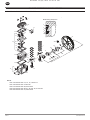
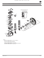
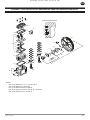
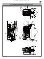
SS3 BARE COMPRESSOR PUMP ASSEMBLY
MODEL SS3 BARE COMPRESSOR PUMP
7
47
45
43 29
25
28
30
31
41
35 8
9
22
23
24
42
19
18
20
44 6
40
10
10
14
15
16
12
36
33
46
4
5
4
3
2
1
39
38
34
37
17
13
21
11
32
27
26
Piston Ring Sequence
Item 12 includes Item 13, 14, 15, 16 and 17
Item 36 includes Item 37, 38 and 39
Item 25 includes Item 26, 27, 28, 29, 30, 31 and 32
Item 21 includes Item 22, 23 and 24
Item 18 includes Item 19 and 20
NOTE
:
RELEASED 16/Apr/2018 18:50:16 GMT

22204911 Rev. D EN-13
EN
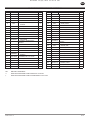
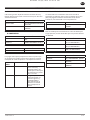
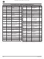
SS3 BARE COMPRESSOR PUMP ASSEMBLY
Item CCN DESCRIPTION Qty.
REF. 18002378 PUMP, BARE COMPRESSOR -
1† 32307092 SET, PISTON RING 2
2 NSS •RING COMPRESSOR 1
3 NSS •RING SPACER 1
4 NSS •RING, OIL CONTROL
SPACER 2
5 NSS •RING, OIL CONTROL 1
6 95033585 PLUG, OIL DRAIN 1
7 96715784 CAPSCREW (HEAD BOLT) 6
8 96716113 CAPSCREW 4
9 96728316 WASHER, SPRING 4
10 97330427 ASSEMBLY, CONNECTING ROD 2
11 96702246 •CAPSCREW 2
12 97338081 ASSEMBLY, CRANKSHAFT-
SERVICE 1
13 NSS •CRANKSHAFT 1
14 NSS •BEARING, MAIN 1
15 NSS •BEARING, BALL 1
16 54375977 •WASHER 1
17 54440045 •CAPSCREW, LEFT HAND
THREAD 1
18 49812050 ASSEMBLY, OIL FILL PLUG 1
19 NSS •PLUG, OIL FILL 1
20 95024394 •O-RING, OIL FILL PLUG 1
21 97330468 ASSEMBLY, PISTON & PIN 2
22 NSS •PISTON 1
23 NSS •PIN, PISTON 1
Item CCN DESCRIPTION Qty.
24 NSS •RING, LOCK 2
25** 97330484 ASSEMBLY, VALVE 1
26 NSS •PLATE, VALVE 1
27 NSS •VALVE, DISCHARGE 2
28 NSS •VALVE, INLET 2
29 NSS •STOP, DISCHARGE 2
30 NSS •RETAINER, INLET 2
31 NSS •SCREW, HEX HEAD 4
32 NSS •NUT 4
33 24655631 BELTWHEEL 1
34 97330500 CAPSCREW 3
35 97330625 CYLINDER 1
36 97338073 ASSEMBLY, END COVER-
SERVICE 1
37 32204521 •SEAL, SHAFT 1
38 NSS •COVER, END 1
39 97331227 •GASKET, END COVER 1
40 97330641 FRAME, COMPRESSOR 1
41** 97330658 GASKET, VALVE PLATE 1
42† 97330666 GASKET, CYLINDER 1
43** 54571609 GASKET, HEAD 1
44 97330682 GLASS, SIGHT 1
45 97330690 HEAD 1
46 70243936 ASSEMBLY, VENT 1
47 70243399 FILTER, AIR 1
NI 70243712 •ELEMENT, FILTER 1
NSS NOT SOLD SEPERATELY
** AVAILABLE INDIVIDUALLY OR IN VALVE KIT 97338107
† AVAILABLE INDIVIDUALLY OR IN PISTON RING KIT 97338115
RELEASED 16/Apr/2018 18:50:16 GMT

EN
EN-14 22204911 Rev. D
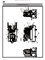
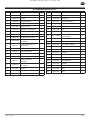
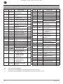
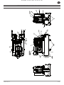
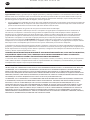
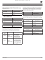
SS3 COMPRESSOR PARTS LIST
21
5
19
4
22
1, 2 11
3
6
7, 8, 40
9
10
12, 27
13, 14
15
16
17
18
20
23A, 23B, 24,
25, 26
28
29
30
31
32
33
34, 38, 39
35
36, 37
RELEASED 16/Apr/2018 18:50:16 GMT

22204911 Rev. D EN-15
EN
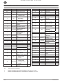
SS3 COMPRESSOR PARTS LIST
Item CCN DESCRIPTION Qty.
1 18002378 PUMP, BARE COMPRESSOR 1
2 56290794 SCREW 4
3 22866552 RECEIVER TANK 1
4 54394036 CAP PLUG 2
5 97171060 HANDLE GRIP 2
6 32027120 MANUAL DRAIN VALVE 2
7 54389572 AXLE 1
8 54506001 WHEEL 1
9 95040184 ELBOW, TUBE 1/2X3/8 1
10 47600594001 VALVE-UNLOADER
ASSEMBLY 1
11 18007138 STUD, MANIFOLD SS3
WHEELBAR 1
12 39155577 ELBOW 2
13 97265912 UNLOADER TUBE 1
14 97182240 NYLON TUBE INSERT 2
15 39128566 NUT 1
16 18007112 BODY, MANIFOLD
Assembly 1
17 18007120 FITTING, MANIFOLD
Assembly 2
18 95871463 NIPPLE 1
19 54494075 PRESSURE GAUGE 2
20 97010094 SAFETY VALVE 1
Item CCN DESCRIPTION Qty.
21 37992849 PRESSURE REGULATOR 1
22 32238354 COUPLER 2
23A 97339451 ENGINE (HONDA) 1
23B 47617263001 ENGINE (KOHLER) 1
24 58879461 CAPSCREW 4
25 54391545 NUT 4
26 95094389 KEY 1
27 47619810001 ACTUATOR, SMALL ENGINE
SLOW-DOWN 1
28 32205601 BELT 1
29 22921860 SHEAVE 1
30 54459508 BELTGUARD, FRONT 1
31 54459516 BELTGUARD, REAR 1
32 97173595 CAPSCREW 14
33 56280159 SCREW 1
34 54640032 BRACE, BELTGUARD 1
35 49812324 PUMP TO UNLOADER TUBE 1
36 97175343 ISOLATOR PAD 4
37 97175350 SCREW 4
38 32175564 SCREW 1
39 39128541 NUT 1
40 54657218 NUT 1
RELEASED 16/Apr/2018 18:50:16 GMT

EN
EN-16 22204911 Rev. D
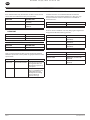
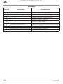
EXTENDED WARRANTY KIT
Each extended warranty kit contains air lters and all season
select lubricant sucient for two years operation.
PART NO DESCRIPTION
47623376001 KIT, EXTENDED WARRANTY
(KOHLER)
97339501 KIT, EXTENDED WARRANTY
(HONDA)
INGERSOLL-RAND SYNTHETIC COMPRESSOR
LUBRICANT
PART NO DESCRIPTION
97338131 LUBRICANT, .5L, BOTTLE
38436721 LUBRICANT, 1L, BOTTLE
AIR FILTER ELEMENT
PART NO DESCRIPTION
70243712 AIR FILTER ELEMENT
STEP SAVER KITS
Step Saver Kits provide all of the parts required to perform
common repair tasks such as piston ring replacement or valve
replacement.
PART NO DESCRIPTION CONTENTS
97338107 KIT, VALVE/GASKET Valve wearing parts and
head gaskets that are
destroyed in replacing
valve parts.
97338115 KIT, RING/GASKET Complete set of piston
rings, a crankshaft seal,
and gaskets that are
destroyed in breaking
the unit down to
replace the rings
CRANKCASE HEATER KIT
Crankcase heaters are recommended when ambient
temperatures are consistently below 32° F (0°C). An easy-
to-install external crankcase heater kit is intended for
aftermarket use.
PART NO DESCRIPTION
97330385 KIT, CRANKCASE HEATER
MULTI-PURPOSE AIR HOSES
These air hose assemblies are heavy duty, light weight hoses
designed for 300 PSIG working pressure.
PART NO DESCRIPTION
32323750 HOSE, AIR 3/8” x 25’ (1/4”
MALE NPT)
32323768 HOSE, AIR 3/8” x 50’ (1/4”
MALE NPT)
32323776 HOSE, AIR 3/8” x 100’ (1/4”
MALE NPT)
ENGINE PARTS
PART NO DESCRIPTION
32498552 OIL, 10W30 ENGINE - QUART
47629343001 COMPLETE, FILTER 5.5HP
(KOHLER)
54405071 ELEMENT, ENGINE AIR FILTER
(HONDA)
KITS & ACCESSORIES
RELEASED 16/Apr/2018 18:50:16 GMT

22204911 Rev. D EN-17
EN
WARRANTY AND LIMITATION OF LIABILITY
WARRANTY
Ingersoll Rand company warrants that the equipment manufactured by it and delivered hereunder shall be free of defects in
material and workmanship for a period of twelve (12) months from the date of placing the equipment in operation or eighteen
(18) months from the date of shipment, whichever shall occur rst. The foregoing warranty period shall apply to all equipment,
except the following:
1. Compressors purchased with an accompanying Extended Warranty Kit that are operated solely on the included Ingersoll
Rand synthetic lubricant will have their bare compressor warranted for the earlier of twenty-four (24) months from the
date of initial operation or thirty (3 0) months from the date of shipment..
2. Replacement parts will be warranted for six (6) months from the date of shipment.
Should any failure to conrm this warranty be reported in writing to the company within said period, the company shall, at
its option, correct such non-conformity by suitable repair to such equipment, or furnish a replacement part F.O.B point of
shipment, provided the purchaser has installed, maintained and operated such equipment in accordance with good industry
practices and has complied with specic recommendations of the company. Accessories or equipment furnished by the
company, but manufactured by others, shall carry whatever warranty the manufacturer conveyed to Ingersoll Rand Company
and which can be passed on to the purchaser. The company shall not be liable for any repairs, replacements, or adjustments to
the equipment or any costs of labor performed by the purchaser without company’s prior written approval.
The company makes no performance warranty unless specically stated within its proposal and the eects of corrosion,
erosion and normal wear and tear are specically excluded from the company’s warranty. In the event performance warranties
are expressly included, the company’s obligation shall be to correct in the manner and for the period of time provided above.
THE COMPANY MAKES NO OTHER WARRANTY OF REPRESENTATION OF ANY KIND WHATSOEVER, EXPRESSED
OR IMPLIED, EXCEPT THAT OF TITLE, AND ALL IMPLIED WARRANTIES OF MERCHANTABILITY AND FITNESS FOR A
PARTICULAR PURPOSE, AND HEREBY DISCLAIMED.
Correction by the company of non-conformities, whether patent or latent, in the manner and for the period of time provided
above, shall constitute fullment of all liabilities of the company and its distributors for such non-conformities with respect to
or arising out of such equipment.
LIMITATION OF LIABILITY
THE REMEDIES OF THE PURCHASER SET FORTH HEREIN ARE EXCLUSIVE, AND THE TOTAL LIABILITY OF THE COMPANY, ITS
DISTRIBUTORS AND SUPPLIERS WITH RESPECT TO CONTRACT OR THE EQUIPMENT AND SERVICES FURNISHED, IN CONNECTION
WITH THE PERFORMANCE OR BRANCH THEREOF, OR FROM THE MANUFACTURE, SALE, DELIVERY, INSTALLATION, REPAIR
OR TECHNICAL DIRECTION COVERED BY OR FURNISHED UNDER CONTRACT, WHETHER BASED ON CONTRACT, WARRANTY,
NEGLIGENCE, INDEMNITY, STRICT LIABILITY OR OTHERWISE SHALL NOT EXCEED THE PURCHASE PRICE OF THE UNIT OF
EQUIPMENT UPON WHICH SUCH LIABILITY IS BASED.
THE COMPANY, ITS DISTRIBUTORS AND ITS SUPPLIERS SHALL IN NO EVENT BE LIABLE TO THE PURCHASER, ANY SUCCESSORS IN
INTEREST OR ANY BENEFICIARY OR ASSIGNEE OF THE CONTRACT FOR ANY CONSEQUENTIAL, INCIDENTAL, INDIRECT, SPECIAL
OR PUNITIVE DAMAGES ARISING OUT OF THIS CONTRACT OR ANY BREACH THEREOF, OR ANY DEFECT IN, OR FAILURE OF , OR
MALFUNCTION OF THE EQUIPMENT, WHETHER OR NOT BASED UPON LOSS OF USE, LOSS PROFITS OR REVENUE, INTEREST, LOST
GOODWILL, WORK STOPPAGE, IMPAIRMENT OF THE OTHER GOODS, LOSS BY REASON OF SHUTDOWN OR NON-OPERATION,
INCREASED FOR SERVICE INTERRUPTION WHETHER OR NOT SUCH LOSS OR DAMAGE IS BASED ON CONTRACT, WARRANTY,
NEGLIGENCE, INDEMNITY, STRICT LIABILITY OR OTHERWISE.
RELEASED 16/Apr/2018 18:50:16 GMT

RELEASED 16/Apr/2018 18:50:16 GMT

RELEASED 16/Apr/2018 18:50:16 GMT

ingersollrandproducts.com
© 2018 Ingersoll Rand
RELEASED 16/Apr/2018 18:50:16 GMT
La page est en cours de chargement...
La page est en cours de chargement...
La page est en cours de chargement...
La page est en cours de chargement...
La page est en cours de chargement...
La page est en cours de chargement...
La page est en cours de chargement...
La page est en cours de chargement...
La page est en cours de chargement...
La page est en cours de chargement...
La page est en cours de chargement...
La page est en cours de chargement...
La page est en cours de chargement...
La page est en cours de chargement...
La page est en cours de chargement...
La page est en cours de chargement...
La page est en cours de chargement...
La page est en cours de chargement...
La page est en cours de chargement...
La page est en cours de chargement...
La page est en cours de chargement...
La page est en cours de chargement...
La page est en cours de chargement...
La page est en cours de chargement...
La page est en cours de chargement...
La page est en cours de chargement...
La page est en cours de chargement...
La page est en cours de chargement...
La page est en cours de chargement...
La page est en cours de chargement...
La page est en cours de chargement...
La page est en cours de chargement...
La page est en cours de chargement...
La page est en cours de chargement...
La page est en cours de chargement...
La page est en cours de chargement...
La page est en cours de chargement...
La page est en cours de chargement...
La page est en cours de chargement...
La page est en cours de chargement...
-
 1
1
-
 2
2
-
 3
3
-
 4
4
-
 5
5
-
 6
6
-
 7
7
-
 8
8
-
 9
9
-
 10
10
-
 11
11
-
 12
12
-
 13
13
-
 14
14
-
 15
15
-
 16
16
-
 17
17
-
 18
18
-
 19
19
-
 20
20
-
 21
21
-
 22
22
-
 23
23
-
 24
24
-
 25
25
-
 26
26
-
 27
27
-
 28
28
-
 29
29
-
 30
30
-
 31
31
-
 32
32
-
 33
33
-
 34
34
-
 35
35
-
 36
36
-
 37
37
-
 38
38
-
 39
39
-
 40
40
-
 41
41
-
 42
42
-
 43
43
-
 44
44
-
 45
45
-
 46
46
-
 47
47
-
 48
48
-
 49
49
-
 50
50
-
 51
51
-
 52
52
-
 53
53
-
 54
54
-
 55
55
-
 56
56
-
 57
57
-
 58
58
-
 59
59
-
 60
60


Ingersoll Rand SS3 Le manuel du propriétaire
- Catégorie
- Compresseurs d'air
- Taper
- Le manuel du propriétaire
- Ce manuel convient également à
dans d''autres langues
Documents connexes
-
Ingersoll Rand SS4L5 Single-Stage Twin Cylinder Pro Air Compressor, 5 HP, 230V, 135 PSI, 60 Gallons Le manuel du propriétaire
-
-
-
Ingersoll-Rand TS4L5 Le manuel du propriétaire
-