Apollo 51000-355 Guide d'installation
- Catégorie
- Protection contre le feu
- Taper
- Guide d'installation

ATTENTION: This manual should be read prior to use and retained for
further information.
GENERAL INFORMATION
The Wireless Smoke Heat Alarm is a 3xAAA battery powered wireless
detector intended for use with a compatible wireless alarm system. The
detector has a built-in wireless transmitter, which communicates with
the control panel. When smoke is detected, the alarm sounds a loud
local alarm and the built-in transmitter sends a signal to the control
panel. The Wireless Smoke Heat Alarm contains an integrated xed
41°F temperature freeze sensor that will send a warning signal based on
temperature detected. This detector is designed to provide protection
with 70-foot spacing capability.
The detector can send alarm, tamper and battery condition messages to
the system’s receiver. Refer to the wireless system’s instruction for the
maximum number of transmitters that can be supported.
CONTENTS OF BOX:
• Wireless Smoke Heat Alarm with base
• Installation guide (APD0601)
• Pack of screws and anchors
• Labels or decals as appropriate
• 3 AAA PC2400 Duracell Procell batteries (1.5V 1100mAh) or 3 AAA
Energizer E92 batteries (1.5V 1100mAh)
51000-355
Wireless Smoke Heat Alarm
Installation Guide

2
INST APD0601 A140513 Wireless Smoke Heat Alarm Install Guide
Status LEDs
Sounder
(do not pulse the sounder
and LED concurrently)
Normal Green ash every 12 seconds Off
Heat Alarm Red ash every 1 second ANSI S3.41 temporal 3
Heat Test Red ash every 1 second ANSI S3.41 temporal 3
Smoke Alarm Red ash every 1 second ANSI S3.41 temporal 3
(press button to hush
for 5-10 minutes)
Smoke Test Red ash every 1 second ANSI S3.41 temporal 3
(press button to hush
for 5-10 minutes)
Test Alarm Red ash every 1 second ANSI S3.41 temporal 3
Freeze Warning 3 yellow ashes
every 4 seconds
Off
Detector Trouble Yellow ash every 4 seconds One chirp every 48 seconds
Low Battery Yellow ash every 12 seconds One chirp every 48
seconds (press button
to hush for 12 hours)
Detector Dirty Yellow ash every 8 seconds One chirp every 48 seconds
Power-up Red, yellow, green
ash sequence
One chirp at the end
of power-up sequence
Tamper Red, yellow, green ash
sequence every 12 seconds
Off
The Wireless Smoke Heat Alarm contains a sounder which generates the
ANSI S3.41 temporal 3 pattern in an alarm condition. In alarm, a message
is also sent to the control panel and the detector’s ID is displayed at
the console. During an alarm condition, pressing the detector’s hush
button will silence the sounder (see table below). The mounting base
installation is simpli ed by the incorporation of features compatible
for both drywall fasteners (not supplied) and other methods.
Tricolored LED (red, yellow, green) and a sounder on the detector
provide local visual and audible indication of the detector’s status as
listed in Table 1.
During initial power-up the LED blinks alternately red, yellow then
green. It takes about 8 seconds for the detector to stabilize.
After power-up has completed and the detector is functioning normally,
the green LED blinks once every 12 seconds.
Detector Trouble: When the detector has a general fault, the yellow LED
blinks once every four seconds and there is a chirp every 48 seconds.
After 12 hours the panel will display a loss of supervision message.
Table 1. Detector status and indication

3
INST APD0601 A140513 Wireless Smoke Heat Alarm Install Guide
Detector Dirty Feature: When the detector has been contaminated, the
yellow LED blinks once every 8 seconds and there is a chirp every 48
seconds. Refer to MAINTENANCE section for cleaning your alarm. After
12 hours the panel will display a loss of supervision message.
Low Battery Detection: The Wireless Smoke Heat Alarm is powered by
3 AAA Duracell Procell or 3 AAA Energizer E92 batteries (included). The
detector regularly checks for a low battery. If a low battery is detected,
the transmitter sends a low battery message to the control panel, which
displays the detector’s ID at low battery. In addition, the yellow LED
of the detector will blink every 12 seconds. The detector’s sounder
will chirp every 48 seconds (yellow LED continues to blink) until the
batteries are replaced. Pressing the hush button will silence the chirps
for 12 hours, if no other trouble conditions exist. The batteries should
be replaced WHEN the chirps begin. Be sure to replace the batteries
with fresh ones.
BATTERY INSTALLATION AND REPLACEMENT
To replace the batteries:
1. Remove the detector from its mounting base by twisting the
detector counterclockwise. Remove and dispose of the batteries
according to your local regulations.
2. To ensure proper power-down sequence, wait a minimum of 20
seconds before installing new batteries.
3. Install 3 new AAA batteries (available from your local Duracell or
Energizer dealer) in the battery compartment. Follow the polarity
diagram inside the compartment. If the batteries are incorrectly
inserted please remove gently with a non-conductive tool and
correctly reinsert.
51000-355
Wireless Smoke Heat Alarm
Installation Guide
ATTENTION: This manual should be read prior to use and retained for
further information.
GENERAL INFORMATION
The Wireless Smoke Heat Alarm is a 3xAAA battery powered wireless
detector intended for use with a compatible wireless alarm system. The
detector has a built-in wireless transmitter, which communicates with the
control panel. When smoke is detected, the alarm sounds a loud local
alarm and the built-in transmitter sends a signal to the control panel.
The Wireless Smoke Heat Alarm contains an integrated fi xed 41°F
temperature freeze sensor that will send a warning signal based on
temperature detected. This detector is designed to provide protection with
70-foot spacing capability.
The detector can send alarm, tamper and battery condition messages to
the system’s receiver. Refer to the wireless system’s instruction for the
maximum number of transmitters that can be supported.
CONTENTS OF BOX:
- Wireless Smoke Heat Alarm with base
- Installation guide (APD0601)
- Pack of screws and fi xings
- Labels or decals as appropriate
- 3 AAA PC2400 Duracell Procell batteries (1.5V 1100mAh)
or 3 AAA Energizer E92 batteries (1.5V 1100mAh)
1
The Wireless Smoke Heat Alarm contains a sounder which generates the
ANSI S3.41 temporal 3 pattern in an alarm condition.
In alarm, a message is also sent to the control panel and the detector’s ID
is displayed at the console. During an alarm condition, pressing the detec-
tor’s hush button will silence the sounder (see table below). The mounting
base installation is simplifi ed by the incorporation of features compatible for
both drywall fasteners (not supplied) and other methods.
Tricolored LED (red, yellow, green) and a sounder on the detector provide
local visual and audible indication of the detector’s status as listed in Table 1.
During initial power-up the LED blinks alternately red, yellow then green.
It takes about 8 seconds for the detector to stabilize.
After power-up has completed and the detector is functioning normally, the
green LED blinks once every 12 seconds.
Detector Trouble: When the detector has a general fault, the yellow LED
blinks once every four seconds and there is a chirp every 48 seconds. After
12 hours the panel will display a loss of supervision message.
Detector Dirty Feature: When the detector has been contaminated, the
yellow LED blinks once every 8 seconds and there is a chirp every 48
seconds. Refer to MAINTENANCE section for cleaning your alarm. After
12 hours the panel will display a loss of supervision message.
Low Battery Detection: The Wireless Smoke Heat Alarm is powered by
3 AAA Duracell Procell or 3 AAA Energizer E92 batteries (included).
The detector regularly checks for a low battery. If a low battery is detected,
the transmitter sends a low battery message to the control panel, which
displays the detector’s ID at low battery. In addition, the yellow LED of the
detector will blink every 12 seconds. The detector’s sounder will chirp every
48 seconds (yellow LED continues to blink) until the batteries are replaced.
Pressing the hush button will silence the chirps for 12 hours, if no other
trouble conditions exist. The batteries should be replaced WHEN the chirps
begin. Be sure to replace the batteries with fresh ones.
BATTERY INSTALLATION AND REPLACEMENT
To replace the batteries:
1.
Remove the detector from its mounting base by twisting the detector
counterclockwise. Remove and dispose of the batteries according to your
local regulations.
2. To ensure proper power-down sequence, wait a minimum of 20 seconds
before installing new batteries.
3. Install 3 new AAA batteries (available from your local Duracell or Ener-
gizer dealer) in the battery compartment. Follow the polarity diagram inside
BOUTON SILENCE/TEST
COMPARTIMENT DE LA BATTERIE
Fig 1. Wireless Smoke Heat Alarm
Table 1. Detector status and indication
Status LEDs
Sounder
(do not pulse the sounder
and LED concurrently)
Normal
Green fl ash every
12 seconds
Off
Heat Alarm
Red fl ash every 1
second
ANSI S3.41 temporal 3
Heat Test
Red fl ash every 1
second
ANSI S3.41 temporal 3
Smoke
Alarm
Red fl ash every 1
second
ANSI S3.41 temporal 3
(press button to hush
for 5-10 minutes)
Smoke Test
Red fl ash every 1
second
ANSI S3.41 temporal 3
(press button to hush
for 5-10 minutes)
Test Alarm
Red fl ash every 1
second
ANSI S3.41 temporal 3
Freeze
Warning
3 yellow fl ashes
every 4 seconds
Off
Detector
Trouble
Yellow fl ash every
4 seconds
One chirp every 48 seconds
Low Battery
Yellow fl ash every 12
seconds
One chirp every 48 seconds
(press button to hush
for 12 hours)
Detector
Dirty
Yellow fl ash every 8
seconds
One chirp every 48 seconds
Power-up
Red, yellow
, green
fl ash
sequence
One chirp at the end
of power-up sequence
T
amper
Red, yellow, green
fl ash
sequence every 12
seconds
Off
IF THE ALARM SOUNDS
• if the smoke alarm sounds, get out and stay out. Never go back inside for
people or pets.
• if you have to escape through smoke, get low and go under the smoke to
your way out.
• Call the fi re department from outside your home.
FOR MORE SAFETY INFORMATION SEE THE WEBSITE: www.nfpa.org/
education
SPECIFICATIONS
Transmitter Frequency: 345.000 MHz (crystal controlled)
Dimensions: Ø 5’’ x 2.5’’ high (Ø 125mm x 63mm high)
Weight (including battery): 8.57 oz (243 g)
Color: White
Spacing rating: 70ft
Audible Signal (ANSI Temporal 3): 85dBA min. in alarm
Sensitivity: 1.5 - 3.5%/foot
Operating Temperature: 40°-100°F (4.4°-37.8°C)
Supplementary heat rating: 135°F
Relative Humidity: 15-90% Non-Condensing
Battery (included): Three (3) AAA PC2400 Duracell Procell
or three (3) AAA Energizer E92 batteries
Regulatory Listing: UL 217
Warranty: Two (2) years
Included Accessories: Mounting Hardware Package
REGULATORY INFORMATION
NOTICE: Unauthorized changes or modifi cations could void the user’s
authority to operate the equipment.
This device complies with Part 15 of the FCC Rules and Industry Canada
licence-exempt RSS standard(s). Operation is subject to the following two
conditions: (1) This device may not cause harmful interference, and (2) this
device must accept any interference received, including interference that
may cause undesired operation of the device.
This equipment has been tested and found to comply with the limits for a
Class B digital device, pursuant to Part 15 of FCC Rules. These limits are
designed to provide reasonable protection against harmful interference in
a residential installation. This equipment generates, uses and can radiate
radio frequency energy and if not installed and used in accordance with
the instructions, may cause harmful interference to radio communications.
However, there is no guarantee that interference will not occur in a particu-
lar installation. If this equipment does cause harmful interference to radio
or television reception, which can be determined by turning the equipment
off and on, the user is encouraged to try to correct the interference by one
or more of the following measures:
• Reorient or relocate the receiving antenna.
• Increase the separation between the equipment and the receiver
• Connect the equipment into an outlet on a circuit different from that to
which the receiver is connected.
• Consult the dealer or an experienced radio/television technician for help
“For your information, The National Fire Alarm Code, NFPA 72, reads as
follows:
“11.5.1 Required Detection.”
“Where required by applicable laws, codes, or standards for a specifi c type
of occupancy, approved single- and multiple-station smoke alarms shall be
installed as follows:
(1) In a sleeping rooms and guest rooms
(2) Outside of each separate dwelling unit sleeping area, within 6.4 m (21
ft) of any door to a sleeping room, the distance measured along a path of
travel
(3) On every level of a dwelling unit, including basements
(4) On every level of a residential board and care occupancy (small facility),
including basements and excluding crawl spaces and unfi nished attics
(5) In the living area(s) of a guest suite
(6) In the living area(s) of a residential board and care occupancy.
(Reprinted with permission from NFPA 72®, National Fire Alarm Code Cop-
yright© 2007 National Fire Protection Association, Quincy, MA 02269. This
reprinted material is not the complete and offi cial position of the National
Fire Protection Association, on the referenced subject which is represented
only by the standard in its entirety.)
(National Fire Alarm Code® and NFPA 72® are registered trademarks of
the National Fire Protection Association, Inc., Quincy, MA 02269.)
In typical single level and multilevel dwelling units and apartment buildings
having similar smoke alarm systems there is a possibility that signals sent
by wireless sensors may be blocked or refl ected by metal before they reach
the alarm Control Panel, even if the signal path has been recently checked
during a weekly test. Blockage can occur if a metal object has been moved
into the sensor’s signal path.
4
Apollo America, Inc.
25 Corporate Drive
Auburn Hills, MI 48326
(248) 332-3900 Phone/Tech. Support
www.apollo-fire.com
INST APD0601 A140513
INST APD0601 A140513
Fig 1. Wireless Smoke Heat Alarm

4
INST APD0601 A140513 Wireless Smoke Heat Alarm Install Guide
4. Reinstall the detector onto the mounting base by turning the
detector clockwise until the mating marks align.
5. After the power-up sequence the green LED should blink about
once every 12 seconds to indicate normal operation. If the batteries
are not installed correctly, the detector will not operate and the
batteries may be damaged. If the detector does not power-up, check
for correct batteries installation and for a fully charged batteries.
6. Test the detector (as described later).
CONSTANT EXPOSURES TO HIGH OR LOW TEMPERATURES OR HIGH
HUMIDITY MAY REDUCE BATTERY LIFE.
PROGRAMMING
Refer to the appropiate compatible control panel programming guide
for the proper procedure required to enroll the wireless smoke/heat
into the system.
RECOMMENDED LOCATIONS FOR SMOKE HEAT ALARM
According to National Fire Protection Association (NFPA) the major
threat from re in a dwelling unit occurs at night when everyone is
asleep. The principal threat to persons in sleeping areas comes from
res in the remainder of the unit; therefore, a smoke detector(s) is best
located between the bedroom areas and the rest of the unit. In units
with only one bedroom area on one oor, the smoke detector(s) should
be located as shown in Figure 2. In dwelling units with more than one
bedroom area or with bedrooms on more than one oor, more than
one smoke detector is required, as shown in Figure 3.
In addition to smoke detectors outside of the sleeping areas, the
device should be installed on each additional story of the dwelling
unit, including the basement. These installations are shown in Figure
4. The living area smoke detector should be installed in the living
room or near the stairway to the upper level, or in both locations. The
basement smoke detector should be installed in close proximity to the
stairway leading to the oor above. Where installed on an open-joisted
ceiling, the detector should be placed on the bottom of the joists. The
detector should be positioned relative to the stairway so as to intercept
smoke coming from a re in the basement before the smoke enters the
stairway.
Smoke detectors are optional where a door is not provided between
living room and recreation room (Figure 5). The smoke from a re
generally rises to the ceiling, spreads out across the ceiling surface, and
begins to bank down from the ceiling. The corner where the ceiling
and wall meet is an air space into which the smoke could have difculty

5
penetrating. In most res, this dead air space measures about 0.1m
(4in.) along the ceiling from the corner and about 0.1m (4in.) down the
wall. Detectors should not be placed in this dead air space, see Figure
6, 7 and 8.
Where NOT to install the alarm:
• Directly above a sink, cooker, stove or oven
• Do not locate detector within 5 feet (1.5 m) of any cooking appliance
• Next to a door or window that would be affected by drafts i.e
extractor fan or air vent
• Outside
• Do not install in any environment that does not comply with the
detector’s environmental specications
2
3
the compartment. If the batteries are incorrectly inserted please remove
gently with a non-conductive tool and correctly reinsert.
4. Reinstall the detector onto the mounting base by turning the detector
clockwise until the mating marks align.
5. After the power-up sequence the green LED should blink about once
every 12 seconds to indicate normal operation. If the batteries are not
installed correctly, the detector will not operate and the batteries may be
damaged. If the detector does not power-up, check for correct batteries
installation and for a fully charged batteries
6. Test the detector (as described later).
CONSTANT EXPOSURES TO HIGH OR LOW TEMPERATURES OR
HIGH HUMIDITY MAY REDUCE BATTERY LIFE.
PROGRAMMING
Refer to the appropiate compatible control panel programming guide for
the proper procedure required to enroll the wireless smoke/heat into the
system.
RECOMMENDED LOCATIONS FOR SMOKE HEAT ALARM
According to National Fire Protection Association (NFPA) the major
threat from fi re in a dwelling unit occurs at night when everyone is asleep.
The principal threat to persons in sleeping areas comes from fi res in
the remainder of the unit; therefore, a smoke detector(s) is best located
between the bedroom areas and the rest of the unit. In units with only one
bedroom area on one fl oor, the smoke detector(s) should be located as
shown in Figure 2. In dwelling units with more than one bedroom area or
with bedrooms on more than one fl oor, more than one smoke detector is
required, as shown in Figure 3.
In addition to smoke detectors outside of the sleeping areas, the device
should be installed on each additional story of the dwelling unit, including
the basement. These installations are shown in Figure 4. The living area
smoke detector should be installed in the living room or near the stairway
to the upper level, or in both locations. The basement smoke detector
should be installed in close proximity to the stairway leading to the fl oor
above. Where installed on an open-joisted ceiling, the detector should
be placed on the bottom of the joists. The detector should be positioned
relative to the stairway so as to intercept smoke coming from a fi re in the
basement before the smoke enters the stairway.
Smoke detectors are optional where a door is not provided between living
room and recreation room (Figure 5).
The smoke from a fi re generally rises to the ceiling, spreads out across
the ceiling surface, and begins to bank down from the ceiling. The corner
where the ceiling and wall meet is an air space into which the smoke could
have diffi culty penetrating. In most fi res, this dead air space measures
about 0.1m (4in.) along the ceiling from the corner and about 0.1m (4in.)
down the wall. Detectors should not be placed in this dead air space, see
Fi
gure 6,7 and 8.
Where NOT to install the alarm:
- Directly above a sink, cooker, stove or oven
- Do not locate detector within 5 feet (1.5 m) of any cooking appliance
- Next to a door or window that would be affected by drafts i.e. extractor fan
or air vent
- Outside
- Do not install in any environment that does not comply with the detector’s
environmental specifi cations
Chambre
Salon
Salle de jeux
Chambre
Cave
IInstallation optionnelle d’un détecteur de fumée s'il
n'y a pas de porte entre le salon et la salle de jeux
Installation d’un détecteur de fumée requise
Entrée
Salle à
manger
Cuisine
Chambre Chambre
Chambre
Salon
TV
room
Cuisine
Salon
Chambre
Chambre
Chambre
Chambre
Salon
Salle à
manger
Cave
Entrée
Chambre
Plafond
Installation acceptable ici
Ne jamais l’installer ici
Installation de la partie
supérieure du détecteur
acceptable ici
Paroi latérale
100 mm (4 in.)
100-mm
(4-in.)
minimum
300-mm
(12-in.)
maximum
Remarque : les mesures
indiquées sont à l’angle
le plus proche du détecteur.
Installation
recommandée
partout dans
cette zone
Installation interdite
dans cette zone
900 mm
(36 in.)
900 mm
(36 in.)
102 mm
(4 in.)
900 mm (3 ft)
102 mm (4 in.)
Pas dans cette zone
N’importe où
dans cette zone
Fig 5. Installation dans une maison
à demi-niveaux
Fig 2. Emplacement des détecteurs
dans des maisons ayant une seule
chambre à coucher sur un étage
Fig 3. Emplacement des détecteurs
dans des maisons de plus d'une
chambre à coucher ou ayant des
chambres sur plus d'un étage
Fig 4. Un détecteur installé à chaque étage
Fig 6. Exemple d’installation appropriée des détecteurs
Fig 8. Exemple d’installation appropriée
de détecteurs sur des plafonds en relief
Fig 7. Exemple d’installation appropriée des détecteurs sur un plafond incliné
recommended for verifying system protection capability.
Direct Heat Method (Hair dryer of 1000-1500 watts)
Direct the heat toward the thermistor. Be sure to hold the heat source about
12 inches from the detector to avoid damage to the plastic. The detector will
reset only after it has time to cool.
A detector that fails to activate with any of these tests should fi rst be
cleaned as outlined in this manual’s MAINTENANCE section. If the detector
still fails to activate, return for repair.
MAINTENANCE
TEST ONCE A WEEK.
WARNING! USE ONLY BATTERIES SPECIFIED. USE OF DIFFERENT
BATTERIES MAY HAVE A DETRIMENTAL EFFECT ON THE SMOKE
ALARM.
YOUR ALARM SHOULD BE CLEANED AT LEAST ONCE A YEAR.
To clean your alarm, remove it from the mounting base. You can clean the
interior of your alarm by using compressed air or vacuum cleaner hose and
blowing or vacuuming through the openings around the perimeter of the
alarm. The outside of the alarm can be wiped with a damp cloth.
After cleaning, reinstall and test your alarm by using the test button. If
cleaning does not restore the alarm to normal operation the alarm should
be replaced.
WARNING: PLEASE READ CAREFULLY AND THOROUGHLY
• NFPA 72 states: Fire-warning equipment for residential occupancies are
capable of protecting about half of the occupants in potentially fatal fi res.
Victims are often intimate with the fi re, too old or too young, or physically or
mentally impaired such that they cannot escape even when warned early
enough that escape should be possible. For these people, other strategies
such as protection-in-place or assisted escape or rescue would be neces-
sary.
• A battery powered alarm must have a battery of the specifi ed type, in
good condition and installed properly.
• Smoke alarms must be tested regularly to make sure the batteries and the
alarm circuits are in good operating condition.
• Smoke alarms cannot provide an alarm if smoke does not reach the
detector. Therefore, smoke alarms may not sense fi res starting in chimneys,
walls, on roofs, on the other side of a closed door or on a different fl oor
• If the alarm is located outside the sleeping room or on a different fl oor, it
may not wake up a sound sleeper.
• Studies have shown that smoke and heat alarms may not awaken all
sleeping individuals, and that it is the responsibility of individuals in the
household that are capable of assisting others to provide assistance to
those who may not be awakened by the alarm sound or those who may be
incapable of safely evacuating the area unassisted.
• The use of alcohol or drugs may also impair one’s ability to hear the
smoke alarm. For maximum protection, a smoke alarm should be installed
in each sleeping area on every level of a home.
• Although smoke alarms can help save lives by providing an early warning
of a fi re, they are not a substitute for an insurance policy. Home owners and
renters should have adequate insurance to protect their properties.
FAMILY ESCAPE PLAN
According to National Fire Protection Association (NFPA) there often is very
little time between the detection of a fi re and the time it becomes deadly.
This interval can be as little as 1 or 2 minutes. Planning and practicing for
fi re conditions with a focus on rapid exit from the residence are important.
Drills should be held so that all family members know the action to be
taken.
SAFETY TIPS
• Make a home escape plan. Draw a map of your home showing all doors
and windows. Discuss the plan with everyone in your home.
• Know at least two ways out of every room, if possible. Make sure all doors
and windows leading outside open easily.
• Have an outside meeting place (like a tree, light pole or mailbox) a safe
distance from the home where everyone should meet.
• Practice your home fi re drill at night and during the day with everyone in
your home, twice a year.
• Practice using different ways out.
• Teach children how to escape on their own in case you can’t help them.
• Close doors behind you as you leave.
TESTING THE DETECTOR
NOTE: Before testing, notify the central station that the detector system is
undergoing maintenance in order to prevent unwanted alarms. Testing the
detector will activate an alarm and send a signal to the panel. Also, the test
function cannot be used if the detector has a trouble condition.
Detectors must be tested after installation and following periodic mainte-
nance.
Testing Detector Operation
This test checks the detector’s sounder, LEDs, and transmitter.
1. The test button is located on the detector housing.
2. Push and hold the test button for a minimum of 5 seconds. The alarm
panel will trigger and then the detector will go into alarm. The sounder
begins the temporal 3 pattern and the red LED blinks. The alarm panel’s
console should display the detector’s name in alarm.
Smoke Test
Hold a smoldering punk stick or cotton wick at the side of the detector
and gently blow smoke through the detector until the unit alarms. Canned
smoke aerosol is also an acceptable method. Smoke detection testing is
- In or below a cupboard
- Where air fl ow would be obstructed by curtains or furniture
- Where dirt or dust could collect and block the sensor
- Where it could be knocked, damaged, or inadvertently removed
This detector shall not be installed in location where the normal ambient
temperature is below 40°F (4.4°C) or where it exceeds 100°F (37.8°C).
THIS EQUIPMENT SHOULD BE INSTALLED IN ACCORDANCE WITH
NFPA 72: NATIONAL FIRE ALARM AND SIGNALING CODE.
MOUNTING THE DETECTOR
Note: These alarm devices should only be installed by a competent engi-
neer/technician.
This device should not be used with a guard.
O
nce a suitable location is found, mount the detector as follows:
1. Refer to the diagram below and install the mounting base on the ceiling
or on the wall (if local ordinances permit) using screw locations as required.
Use the two screws and anchors provided. Maneuver the base so the
screws are at the elbow of the screw slots and secure.
2. Fit the detector inside the base by aligning it over the base as shown
(detector’s alignment notch should be slightly offset from mounting base
tamper release tab), then turn the detector in a clockwise direction until it
clicks into place.
3. Test the detector after completing the installation (as described in the
TESTING THE DETECTOR section of this manual) and refer to the control
system’s instructions for additional information concerning the use of wire-
less devices.
Ne pas fixer le détecteur sur des panneaux de plafond amobibles
100 mm (4 in.) minimum
100 mm (4 in.)
minimum
Fig 9. Installation du détecteur
INST APD0601 A140513
INST APD0601 A140513
Salle à
manger

6
INST APD0601 A140513 Wireless Smoke Heat Alarm Install Guide
• In or below a cupboard
• Where air ow would be obstructed by curtains or furniture
• Where dirt or dust could collect and block the sensor
• Where it could be knocked, damaged, or inadvertently removed
This detector shall not be installed in location where the normal ambient
temperature is below 40°F (4.4°C) or where it exceeds 100°F (37.8°C).
THIS EQUIPMENT SHOULD BE INSTALLED IN ACCORDANCE WITH
NFPA 72: NATIONAL FIRE ALARM AND SIGNALING CODE.
MOUNTING THE DETECTOR
Note: These alarm devices should only be installed by a competent
engineer/technician.
This device should not be used with a guard.
Once a suitable location is found, mount the detector as follows:
1. Refer to the diagram below and install the mounting base on the
ceiling or on the wall (if local ordinances permit) using screw
locations as required. Use the two screws and anchors provided.
Maneuver the base so the screws are at the elbow of the screw
slots and secure.
2. Fit the detector inside the base by aligning it over the base as
shown (detector’s alignment notch should be slightly offset from
mounting base tamper release tab), then turn the detector in a
clockwise direction until it clicks into place.
3. Test the detector after completing the installation (as described
in the TESTING THE DETECTOR section of this manual) and refer
to the control system’s instructions for additional information
concerning the use of wireless devices.
2
3
the compartment. If the batteries are incorrectly inserted please remove
gently with a non-conductive tool and correctly reinsert.
4. Reinstall the detector onto the mounting base by turning the detector
clockwise until the mating marks align.
5. After the power-up sequence the green LED should blink about once
every 12 seconds to indicate normal operation. If the batteries are not
installed correctly, the detector will not operate and the batteries may be
damaged. If the detector does not power-up, check for correct batteries
installation and for a fully charged batteries
6. Test the detector (as described later).
CONSTANT EXPOSURES TO HIGH OR LOW TEMPERATURES OR
HIGH HUMIDITY MAY REDUCE BATTERY LIFE.
PROGRAMMING
Refer to the appropiate compatible control panel programming guide for
the proper procedure required to enroll the wireless smoke/heat into the
system.
RECOMMENDED LOCATIONS FOR SMOKE HEAT ALARM
According to National Fire Protection Association (NFPA) the major
threat from fi re in a dwelling unit occurs at night when everyone is asleep.
The principal threat to persons in sleeping areas comes from fi res in
the remainder of the unit; therefore, a smoke detector(s) is best located
between the bedroom areas and the rest of the unit. In units with only one
bedroom area on one fl oor, the smoke detector(s) should be located as
shown in Figure 2. In dwelling units with more than one bedroom area or
with bedrooms on more than one fl oor, more than one smoke detector is
required, as shown in Figure 3.
In addition to smoke detectors outside of the sleeping areas, the device
should be installed on each additional story of the dwelling unit, including
the basement. These installations are shown in Figure 4. The living area
smoke detector should be installed in the living room or near the stairway
to the upper level, or in both locations. The basement smoke detector
should be installed in close proximity to the stairway leading to the fl oor
above. Where installed on an open-joisted ceiling, the detector should
be placed on the bottom of the joists. The detector should be positioned
relative to the stairway so as to intercept smoke coming from a fi re in the
basement before the smoke enters the stairway.
Smoke detectors are optional where a door is not provided between living
room and recreation room (Figure 5).
The smoke from a fi re generally rises to the ceiling, spreads out across
the ceiling surface, and begins to bank down from the ceiling. The corner
where the ceiling and wall meet is an air space into which the smoke could
have diffi culty penetrating. In most fi res, this dead air space measures
about 0.1m (4in.) along the ceiling from the corner and about 0.1m (4in.)
down the wall. Detectors should not be placed in this dead air space, see
Fi
gure 6,7 and 8.
Where NOT to install the alarm:
- Directly above a sink, cooker, stove or oven
- Do not locate detector within 5 feet (1.5 m) of any cooking appliance
- Next to a door or window that would be affected by drafts i.e. extractor fan
or air vent
- Outside
- Do not install in any environment that does not comply with the detector’s
environmental specifi cations
Chambre
Salon
Salle de jeux
Chambre
Cave
IInstallation optionnelle d’un détecteur de fumée s'il
n'y a pas de porte entre le salon et la salle de jeux
Installation d’un détecteur de fumée requise
Entrée
Salle à
manger
Cuisine
Chambre Chambre
Chambre
Salon
TV
room
Cuisine
Salon
Chambre
Chambre
Chambre
Chambre
Salon
Salle à
manger
Cave
Entrée
Chambre
Plafond
Installation acceptable ici
Ne jamais l’installer ici
Installation de la partie
supérieure du détecteur
acceptable ici
Paroi latérale
100 mm (4 in.)
100-mm
(4-in.)
minimum
300-mm
(12-in.)
maximum
Remarque : les mesures
indiquées sont à l’angle
le plus proche du détecteur.
Installation
recommandée
partout dans
cette zone
Installation interdite
dans cette zone
900 mm
(36 in.)
900 mm
(36 in.)
102 mm
(4 in.)
900 mm (3 ft)
102 mm (4 in.)
Pas dans cette zone
N’importe où
dans cette zone
Fig 5. Installation dans une maison
à demi-niveaux
Fig 2. Emplacement des détecteurs
dans des maisons ayant une seule
chambre à coucher sur un étage
Fig 3. Emplacement des détecteurs
dans des maisons de plus d'une
chambre à coucher ou ayant des
chambres sur plus d'un étage
Fig 4. Un détecteur installé à chaque étage
Fig 6. Exemple d’installation appropriée des détecteurs
Fig 8. Exemple d’installation appropriée
de détecteurs sur des plafonds en relief
Fig 7. Exemple d’installation appropriée des détecteurs sur un plafond incliné
recommended for verifying system protection capability.
Direct Heat Method (Hair dryer of 1000-1500 watts)
Direct the heat toward the thermistor. Be sure to hold the heat source about
12 inches from the detector to avoid damage to the plastic. The detector will
reset only after it has time to cool.
A detector that fails to activate with any of these tests should fi rst be
cleaned as outlined in this manual’s MAINTENANCE section. If the detector
still fails to activate, return for repair.
MAINTENANCE
TEST ONCE A WEEK.
WARNING! USE ONLY BATTERIES SPECIFIED. USE OF DIFFERENT
BATTERIES MAY HAVE A DETRIMENTAL EFFECT ON THE SMOKE
ALARM.
YOUR ALARM SHOULD BE CLEANED AT LEAST ONCE A YEAR.
To clean your alarm, remove it from the mounting base. You can clean the
interior of your alarm by using compressed air or vacuum cleaner hose and
blowing or vacuuming through the openings around the perimeter of the
alarm. The outside of the alarm can be wiped with a damp cloth.
After cleaning, reinstall and test your alarm by using the test button. If
cleaning does not restore the alarm to normal operation the alarm should
be replaced.
WARNING: PLEASE READ CAREFULLY AND THOROUGHLY
• NFPA 72 states: Fire-warning equipment for residential occupancies are
capable of protecting about half of the occupants in potentially fatal fi res.
Victims are often intimate with the fi re, too old or too young, or physically or
mentally impaired such that they cannot escape even when warned early
enough that escape should be possible. For these people, other strategies
such as protection-in-place or assisted escape or rescue would be neces-
sary.
• A battery powered alarm must have a battery of the specifi ed type, in
good condition and installed properly.
• Smoke alarms must be tested regularly to make sure the batteries and the
alarm circuits are in good operating condition.
• Smoke alarms cannot provide an alarm if smoke does not reach the
detector. Therefore, smoke alarms may not sense fi res starting in chimneys,
walls, on roofs, on the other side of a closed door or on a different fl oor
• If the alarm is located outside the sleeping room or on a different fl oor, it
may not wake up a sound sleeper.
• Studies have shown that smoke and heat alarms may not awaken all
sleeping individuals, and that it is the responsibility of individuals in the
household that are capable of assisting others to provide assistance to
those who may not be awakened by the alarm sound or those who may be
incapable of safely evacuating the area unassisted.
• The use of alcohol or drugs may also impair one’s ability to hear the
smoke alarm. For maximum protection, a smoke alarm should be installed
in each sleeping area on every level of a home.
• Although smoke alarms can help save lives by providing an early warning
of a fi re, they are not a substitute for an insurance policy. Home owners and
renters should have adequate insurance to protect their properties.
FAMILY ESCAPE PLAN
According to National Fire Protection Association (NFPA) there often is very
little time between the detection of a fi re and the time it becomes deadly.
This interval can be as little as 1 or 2 minutes. Planning and practicing for
fi re conditions with a focus on rapid exit from the residence are important.
Drills should be held so that all family members know the action to be
taken.
SAFETY TIPS
• Make a home escape plan. Draw a map of your home showing all doors
and windows. Discuss the plan with everyone in your home.
• Know at least two ways out of every room, if possible. Make sure all doors
and windows leading outside open easily.
• Have an outside meeting place (like a tree, light pole or mailbox) a safe
distance from the home where everyone should meet.
• Practice your home fi re drill at night and during the day with everyone in
your home, twice a year.
• Practice using different ways out.
• Teach children how to escape on their own in case you can’t help them.
• Close doors behind you as you leave.
TESTING THE DETECTOR
NOTE: Before testing, notify the central station that the detector system is
undergoing maintenance in order to prevent unwanted alarms. Testing the
detector will activate an alarm and send a signal to the panel. Also, the test
function cannot be used if the detector has a trouble condition.
Detectors must be tested after installation and following periodic mainte-
nance.
Testing Detector Operation
This test checks the detector’s sounder, LEDs, and transmitter.
1. The test button is located on the detector housing.
2. Push and hold the test button for a minimum of 5 seconds. The alarm
panel will trigger and then the detector will go into alarm. The sounder
begins the temporal 3 pattern and the red LED blinks. The alarm panel’s
console should display the detector’s name in alarm.
Smoke Test
Hold a smoldering punk stick or cotton wick at the side of the detector
and gently blow smoke through the detector until the unit alarms. Canned
smoke aerosol is also an acceptable method. Smoke detection testing is
- In or below a cupboard
- Where air fl ow would be obstructed by curtains or furniture
- Where dirt or dust could collect and block the sensor
- Where it could be knocked, damaged, or inadvertently removed
This detector shall not be installed in location where the normal ambient
temperature is below 40°F (4.4°C) or where it exceeds 100°F (37.8°C).
THIS EQUIPMENT SHOULD BE INSTALLED IN ACCORDANCE WITH
NFPA 72: NATIONAL FIRE ALARM AND SIGNALING CODE.
MOUNTING THE DETECTOR
Note: These alarm devices should only be installed by a competent engi-
neer/technician.
This device should not be used with a guard.
O
nce a suitable location is found, mount the detector as follows:
1. Refer to the diagram below and install the mounting base on the ceiling
or on the wall (if local ordinances permit) using screw locations as required.
Use the two screws and anchors provided. Maneuver the base so the
screws are at the elbow of the screw slots and secure.
2. Fit the detector inside the base by aligning it over the base as shown
(detector’s alignment notch should be slightly offset from mounting base
tamper release tab), then turn the detector in a clockwise direction until it
clicks into place.
3. Test the detector after completing the installation (as described in the
TESTING THE DETECTOR section of this manual) and refer to the control
system’s instructions for additional information concerning the use of wire-
less devices.
Ne pas fixer le détecteur sur des panneaux de plafond amobibles
100 mm (4 in.) minimum
100 mm (4 in.)
minimum
Fig 9. Installation du détecteur
INST APD0601 A140513
INST APD0601 A140513
Salle à
manger

7
INST APD0601 A140513 Wireless Smoke Heat Alarm Install Guide
TESTING THE DETECTOR
NOTE: Before testing, notify the central station that the detector system
is undergoing maintenance in order to prevent unwanted alarms. Testing
the detector will activate an alarm and send a signal to the panel. Also,
the test function cannot be used if the detector has a trouble condition.
Detectors must be tested after installation and following periodic
maintenance.
Testing Detector Operation
This test checks the detector’s sounder, LEDs, and transmitter.
1. The test button is located on the detector housing.
2. Push and hold the test button for a minimum of 5 seconds. The
alarm panel will trigger and then the detector will go into alarm. The
sounder begins the temporal 3 pattern and the red LED blinks. The
alarm panel’s console should display the detector’s name in alarm.
Smoke Test
Hold a smoldering punk stick or cotton wick at the side of the detector
and gently blow smoke through the detector until the unit alarms.
Canned smoke aerosol is also an acceptable method. Smoke detection
testing is recommended for verifying system protection capability.
Direct Heat Method (Hair dryer of 1000-1500 watts)
Direct the heat toward the thermistor. Be sure to hold the heat source
about 12 inches from the detector to avoid damage to the plastic. The
detector will reset only after it has time to cool.
A detector that fails to activate with any of these tests should rst be
cleaned as outlined in this manual’s MAINTENANCE section. If the
detector still fails to activate, return for repair.
MAINTENANCE
TEST ONCE A WEEK.
WARNING! USE ONLY BATTERIES SPECIFIED. USE OF DIFFERENT
BATTERIES MAY HAVE A DETRIMENTAL EFFECT ON THE SMOKE ALARM.
YOUR ALARM SHOULD BE CLEANED AT LEAST ONCE A YEAR.
To clean your alarm, remove it from the mounting base. You can clean
the interior of your alarm by using compressed air or vacuum cleaner
hose and blowing or vacuuming through the openings around the
perimeter of the alarm. The outside of the alarm can be wiped with a
damp cloth.
After cleaning, reinstall and test your alarm by using the test button.
If cleaning does not restore the alarm to normal operation the alarm
should be replaced.

8
INST APD0601 A140513 Wireless Smoke Heat Alarm Install Guide
WARNING: PLEASE READ CAREFULLY AND THOROUGHLY
• NFPA 72 states: Fire-warning equipment for residential occupancies
are capable of protecting about half of the occupants in potentially
fatal res. Victims are often intimate with the re, too old or too
young, or physically or mentally impaired such that they cannot
escape even when warned early enough that escape should be
possible. For these people, other strategies such as protection-in-
place or assisted escape or rescue would be necessary.
• A battery powered alarm must have a battery of the speci ed type,
in good condition and installed properly.
• Smoke alarms must be tested regularly to make sure the batteries
and the alarm circuits are in good operating condition.
• Smoke alarms cannot provide an alarm if smoke does not reach the
detector. Therefore, smoke alarms may not sense res starting in
chimneys, walls, on roofs, on the other side of a closed door or on a
different oor.
• If the alarm is located outside the sleeping room or on a different
oor, it may not wake up a sound sleeper.
• Studies have shown that smoke and heat alarms may not awaken all
sleeping individuals, and that it is the responsibility of individuals
in the household that are capable of assisting others to provide
assistance to those who may not be awakened by the alarm sound or
those who may be incapable of safely evacuating the area unassisted.
• The use of alcohol or drugs may also impair one’s ability to hear the
smoke alarm. For maximum protection, a smoke alarm should be
installed in each sleeping area on every level of a home.
• Although smoke alarms can help save lives by providing an early
warning of a re, they are not a substitute for an insurance policy.
Home owners and renters should have adequate insurance to
protect their properties.
FAMILY ESCAPE PLAN
According to National Fire Protection Association (NFPA) there often
is very little time between the detection of a re and the time it
becomes deadly. This interval can be as little as 1 or 2 minutes. Planning
and practicing for re conditions with a focus on rapid exit from the
residence are important. Drills should be held so that all family members
know the action to be taken.
SAFETY TIPS
• Make a home escape plan. Draw a map of your home showing all
doors and windows. Discuss the plan with everyone in your home.

9
INST APD0601 A140513 Wireless Smoke Heat Alarm Install Guide
• Know at least two ways out of every room, if possible. Make sure all
doors and windows leading outside open easily.
• Have an outside meeting place (like a tree, light pole or mailbox) a
safe distance from the home where everyone should meet.
• Practice your home re drill at night and during the day with everyone
in your home, twice a year.
• Practice using different ways out.
• Teach children how to escape on their own in case you can’t help
them.
• Close doors behind you as you leave.
IF THE ALARM SOUNDS
• if the smoke alarm sounds, get out and stay out. Never go back inside
for people or pets.
• if you have to escape through smoke, get low and go under the
smoke to your way out.
• Call the re department from outside your home. FOR MORE SAFETY
INFORMATION SEE THE WEBSITE: www.nfpa.org/education
SPECIFICATIONS
• Transmitter Frequency: 345.000 MHz (crystal controlled)
• Dimensions: Ø 5’’ x 2.5’’ high (Ø 125mm x 63mm high)
• Weight (including battery): 8.57 oz (243 g)
• Color: White
• Spacing rating: 70ft
• Audible Signal (ANSI Temporal 3): 85dBA min. in alarm
• Sensitivity: 1.5 - 3.5%/foot
• Operating Temperature: 40°-100°F (4.4°-37.8°C)
• Supplementary heat rating: 135°F
• Relative Humidity: 15-90% Non-Condensing
• Battery (included): Three (3) AAA PC2400 Duracell Procell or three
(3) AAA Energizer E92 batteries
• Regulatory Listing: UL 217
• Warranty: Two (2) years
• Included Accessories: Mounting Hardware Package
REGULATORY INFORMATION NOTICE:
Unauthorized changes or modi cations could void the user’s authority
to operate the equipment.
This device complies with Part 15 of the FCC Rules and Industry Canada
licence-exempt RSS standard(s). Operation is subject to the following
two conditions: (1) This device may not cause harmful interference,
and (2) this device must accept any interference received, including

10
INST APD0601 A140513 Wireless Smoke Heat Alarm Install Guide
interference that may cause undesired operation of the device.
This equipment has been tested and found to comply with the limits
for a Class B digital device, pursuant to Part 15 of FCC Rules. These
limits are designed to provide reasonable protection against harmful
interference in a residential installation. This equipment generates, uses
and can radiate radio frequency energy and if not installed and used
in accordance with the instructions, may cause harmful interference
to radio communications. However, there is no guarantee that
interference will not occur in a particular installation. If this equipment
does cause harmful interference to radio or television reception, which
can be determined by turning the equipment off and on, the user is
encouraged to try to correct the interference by one or more of the
following measures:
• Reorient or relocate the receiving antenna.
• Increase the separation between the equipment and the receiver
• Connect the equipment into an outlet on a circuit different from
that to which the receiver is connected.
• Consult the dealer or an experienced radio/television technician
for help
“For your information, The National Fire Alarm Code, NFPA 72, reads as
follows:
“11.5.1 Required Detection.”
“Where required by applicable laws, codes, or standards for a specic
type of occupancy, approved single- and multiple-station smoke alarms
shall be installed as follows:
1. In a sleeping rooms and guest rooms
2. Outside of each separate dwelling unit sleeping area, within 6.4 m
(21 ft) of any door to a sleeping room, the distance measured along
a path of travel
3. On every level of a dwelling unit, including basements
4. On every level of a residential board and care occupancy (small
facility), including basements and excluding crawl spaces and un
nished attics
5. In the living area(s) of a guest suite
6. In the living area(s) of a residential board and care occupancy.
(Reprinted with permission from NFPA 72®, National Fire Alarm Code
Copyright © 2007 National Fire Protection Association, Quincy, MA
02269. This reprinted material is not the complete and of cial position
of the National Fire Protection Association, on the referenced subject
which is represented only by the standard in its entirety.)
(National Fire Alarm Code® and NFPA 72
®
are registered trademarks of
the National Fire Protection Association, Inc., Quincy, MA 02269.)

11
INST APD0601 A140513 Wireless Smoke Heat Alarm Install Guide
In typical single level and multilevel dwelling units and apartment
buildings having similar smoke alarm systems there is a possibility that
signals sent by wireless sensors may be blocked or reected by metal
before they reach the alarm Control Panel, even if the signal path has
been recently checked during a weekly test. Blockage can occur if a
metal object has been moved into the sensor’s signal path.

ATTENTION: Vous devez lire ce manuel avant de l'utiliser et le
conserver pour les références futures.
RENSEIGNEMENTS GÉNÉRAUX
Le détecteur de chaleur et de fumée sans l est un détecteur sans l
alimenté par 3 piles AAA conçu pour être utilisé avec des systèmes
d'alarme sans l compatibles. Le détecteur est doté d'un émetteur sans
l intégré qui communique avec le panneau de commande. Lorsque
de la fumée est détectée, l'alarme retentit comme une sonnerie
locale bruyante et l'émetteur intégré envoie un signal au panneau de
commande. Le détecteur de chaleur et de fumée sans l contient un
capteur de gel intégré xé à une température de 5 °C qui envoie un
signal d'alarme en fonction de la température détectée. Ce détecteur a
été conçu pour fournir une protection dans un rayon de 70pieds.
Il peut envoyer des messages concernant le statut de l’alarme, du
dispositif de sécurité et des messages sur l'état des piles au récepteur
du système. Reportez-vous aux instructions du système sans l pour
connaître le nombre maximum d'émetteurs pouvant être pris en charge.
CONTENU DE LA BOÎTE:
• Détecteur de chaleur et de fumée sans l avec base
• Guide d'installation (APD0601)
• Paquet de vis et de pièces d'ancrage
• Étiquettes ou décalcomanies au besoin
• 3 piles Duracell Procell AAA PC2400 (1,5V 1 100mAh) ou 3 piles
Energizer E92 AAA (1,5V 1 100mAh)
51000-355
Détecteur de chaleur et de fumée sans
l Guide d'installation

13
Guide d'installation du détecteur de chaleur et de fumée sans l INST APD0601 A140513
État DEL
Sonde
(n'appuyez pas simultanément sur
la sonde et la DEL)
Normal
Clignote en vert toutes les 12 secondes
Désactivé
Détecteur de chaleur
Clignote en rouge chaque seconde ANSI S3.41 temporel 3
Épreuve de résis-
tance à la chaleur
Clignote en rouge chaque se-
conde
ANSI S3.41 temporel 3
Détecteur de
fumée
Clignote en rouge chaque se-
conde
ANSI S3.41 temporel 3
(appuyez sur le bouton pour
l'arrêter pendant
5 à 10 minutes)
Test de fumée Clignote en rouge chaque se-
conde
ANSI S3.41 temporel 3
(appuyez sur le bouton pour
l'arrêter pendant
5 à 10 minutes)
Tester le détecteur Clignote en rouge chaque seconde ANSI S3.41 temporel 3
Alarme de gel Clignote en jaune 3 fois
toutes les 4 secondes
Désactivé
Défaut du détecteur
Clignote en jaune toutes les 4 secondes Un bip sonore toutes les 48 secondes
Piles faibles Clignote en jaune toutes les
12 secondes
Un bip sonore toutes les 48
secondes (appuyez sur le bouton
pour l'arrêter pendant 12 heures)
Détecteur sale
Clignote en jaune toutes les 8 secondes Un bip sonore toutes les 48 secondes
Activation Rouge, jaune, vert
séquence de clignotement
Un bip sonore à la n
de la séquence d'activation
Languette de
sécurité
Rouge, jaune, vert
séquence de clignotement toutes les
12 secondes
Désactivé
Le détecteur de fumée et de chaleur sans l contient une sonde qui émet une
séquence temporelle 3 ANSI S3.41 dans des conditions d'alarme. En état d'alerte, un
message est envoyé aussi au panneau de commande et l'ID du détecteur s'afche sur
la console. En cas de déclenchement d'une alarme, appuyez sur le bouton de silence
du détecteur pour arrêter la sonde (voir le tableau ci-dessous). L'installation du socle
de xation est simpliée grâce à l'intégration de caractéristiques compatibles avec
les attaches pour cloisons sèches (non fournies) et d'autres méthodes.
La DEL tricolore (rouge, jaune, vert) et la sonde du détecteur émettent des signaux
visuels et sonores locaux relatifs au statut du détecteur tel que l'indique le Tableau 1.
Lors de la première mise sous tension, la DEL clignote alternativement entre le
rouge, le jaune et le vert. Il faut environ 8 secondes pour que le détecteur se stabilise.
À la n de la mise sous tension, si le détecteur fonctionne normalement, la DEL verte
clignote une fois toutes les 12 secondes.
Défaut du détecteur: Lorsque le détecteur est en panne, la DEL jaune clignote une
fois toutes les quatre secondes et un bip sonore retentit toutes les 48 secondes.
Après 12 heures, le panneau afche un message de perte de supervision.
Tableau 1. Statut et indications du détecteur

14
Guide d'installation du détecteur de chaleur et de fumée sans l INST APD0601 A140513
Fonction détecteur sale: Lorsque le détecteur est contaminé, la DEL jaune clignote
une fois toutes les 8 secondes et un bip sonore retentit toutes les 48 secondes.
Reportez-vous à la section MAINTENANCE pour le nettoyage de votre détecteur.
Au bout de 12 heures le panneau de contrôle afche un message de perte de
contrôle.
Détection d'un signal de piles faibles: Le détecteur de chaleur et de fumée sans l est
alimenté par 3 piles AAA Duracell Procell ou 3 piles AAA Energizer E92 (incluses).
Il vérie régulièrement le niveau des piles. Si des piles faibles sont détectées,
l’émetteur envoie un message de piles faibles au panneau de commande qui
afche l’identiant du détecteur ayant un faible niveau. Par ailleurs, la DEL jaune
du détecteur va clignoter toutes les 12 secondes. La sonde du détecteur émet un
signal sonore toutes les 48 secondes (la DEL jaune continue à clignoter) jusqu’à
ce que les piles soient remplacées. Appuyez sur le bouton silence pour arrêter
les bips sonores pendant 12 heures, s'il n'existe aucun autre défaut. Remplacez
les piles dès que les bips sonores recommencent. Assurez-vous de remplacer
les anciennes piles par des neuves.
INSTALLATION ET REMPLACEMENT DES PILES
Pour remplacer les piles:
1. Déposez le détecteur de son socle de xation en le tournant dans le sens
antihoraire. Enlevez les piles et mettez-les au rebut selon les réglementations
locales.
2. An de garantir une mise hors tension appropriée, attendez 20 secondes au
moins avant d'installer les piles neuves.
3. Installez 3 nouvelles piles AAA (disponibles auprès votre détaillant Duracell
ou Energizer local) dans le compartiment à piles. Suivez le schéma de
polarité présenté dans le compartiment. Si les piles sont insérées de façon
incorrecte, veuillez les enlever doucement avec un outil isolant et réinsérez-
les correctement.
51000-355
Wireless Smoke Heat Alarm
Installation Guide
ATTENTION: This manual should be read prior to use and retained for
further information.
GENERAL INFORMATION
The Wireless Smoke Heat Alarm is a 3xAAA battery powered wireless
detector intended for use with a compatible wireless alarm system. The
detector has a built-in wireless transmitter, which communicates with the
control panel. When smoke is detected, the alarm sounds a loud local
alarm and the built-in transmitter sends a signal to the control panel.
The Wireless Smoke Heat Alarm contains an integrated fi xed 41°F
temperature freeze sensor that will send a warning signal based on
temperature detected. This detector is designed to provide protection with
70-foot spacing capability.
The detector can send alarm, tamper and battery condition messages to
the system’s receiver. Refer to the wireless system’s instruction for the
maximum number of transmitters that can be supported.
CONTENTS OF BOX:
- Wireless Smoke Heat Alarm with base
- Installation guide (APD0601)
- Pack of screws and fi xings
- Labels or decals as appropriate
- 3 AAA PC2400 Duracell Procell batteries (1.5V 1100mAh)
or 3 AAA Energizer E92 batteries (1.5V 1100mAh)
1
The Wireless Smoke Heat Alarm contains a sounder which generates the
ANSI S3.41 temporal 3 pattern in an alarm condition.
In alarm, a message is also sent to the control panel and the detector’s ID
is displayed at the console. During an alarm condition, pressing the detec-
tor’s hush button will silence the sounder (see table below). The mounting
base installation is simplifi ed by the incorporation of features compatible for
both drywall fasteners (not supplied) and other methods.
Tricolored LED (red, yellow, green) and a sounder on the detector provide
local visual and audible indication of the detector’s status as listed in Table 1.
During initial power-up the LED blinks alternately red, yellow then green.
It takes about 8 seconds for the detector to stabilize.
After power-up has completed and the detector is functioning normally, the
green LED blinks once every 12 seconds.
Detector Trouble: When the detector has a general fault, the yellow LED
blinks once every four seconds and there is a chirp every 48 seconds. After
12 hours the panel will display a loss of supervision message.
Detector Dirty Feature: When the detector has been contaminated, the
yellow LED blinks once every 8 seconds and there is a chirp every 48
seconds. Refer to MAINTENANCE section for cleaning your alarm. After
12 hours the panel will display a loss of supervision message.
Low Battery Detection: The Wireless Smoke Heat Alarm is powered by
3 AAA Duracell Procell or 3 AAA Energizer E92 batteries (included).
The detector regularly checks for a low battery. If a low battery is detected,
the transmitter sends a low battery message to the control panel, which
displays the detector’s ID at low battery. In addition, the yellow LED of the
detector will blink every 12 seconds. The detector’s sounder will chirp every
48 seconds (yellow LED continues to blink) until the batteries are replaced.
Pressing the hush button will silence the chirps for 12 hours, if no other
trouble conditions exist. The batteries should be replaced WHEN the chirps
begin. Be sure to replace the batteries with fresh ones.
BATTERY INSTALLATION AND REPLACEMENT
To replace the batteries:
1.
Remove the detector from its mounting base by twisting the detector
counterclockwise. Remove and dispose of the batteries according to your
local regulations.
2. To ensure proper power-down sequence, wait a minimum of 20 seconds
before installing new batteries.
3. Install 3 new AAA batteries (available from your local Duracell or Ener-
gizer dealer) in the battery compartment. Follow the polarity diagram inside
BOUTON SILENCE/TEST
COMPARTIMENT DE LA BATTERIE
Fig 1. Wireless Smoke Heat Alarm
Table 1. Detector status and indication
Status LEDs
Sounder
(do not pulse the sounder
and LED concurrently)
Normal
Green fl ash every
12 seconds
Off
Heat Alarm
Red fl ash every 1
second
ANSI S3.41 temporal 3
Heat Test
Red fl ash every 1
second
ANSI S3.41 temporal 3
Smoke
Alarm
Red fl ash every 1
second
ANSI S3.41 temporal 3
(press button to hush
for 5-10 minutes)
Smoke Test
Red fl ash every 1
second
ANSI S3.41 temporal 3
(press button to hush
for 5-10 minutes)
Test Alarm
Red fl ash every 1
second
ANSI S3.41 temporal 3
Freeze
Warning
3 yellow fl ashes
every 4 seconds
Off
Detector
Trouble
Yellow fl ash every
4 seconds
One chirp every 48 seconds
Low Battery
Yellow fl ash every 12
seconds
One chirp every 48 seconds
(press button to hush
for 12 hours)
Detector
Dirty
Yellow fl ash every 8
seconds
One chirp every 48 seconds
Power-up
Red, yellow
, green
fl ash
sequence
One chirp at the end
of power-up sequence
T
amper
Red, yellow, green
fl ash
sequence every 12
seconds
Off
IF THE ALARM SOUNDS
• if the smoke alarm sounds, get out and stay out. Never go back inside for
people or pets.
• if you have to escape through smoke, get low and go under the smoke to
your way out.
• Call the fi re department from outside your home.
FOR MORE SAFETY INFORMATION SEE THE WEBSITE: www.nfpa.org/
education
SPECIFICATIONS
Transmitter Frequency: 345.000 MHz (crystal controlled)
Dimensions: Ø 5’’ x 2.5’’ high (Ø 125mm x 63mm high)
Weight (including battery): 8.57 oz (243 g)
Color: White
Spacing rating: 70ft
Audible Signal (ANSI Temporal 3): 85dBA min. in alarm
Sensitivity: 1.5 - 3.5%/foot
Operating Temperature: 40°-100°F (4.4°-37.8°C)
Supplementary heat rating: 135°F
Relative Humidity: 15-90% Non-Condensing
Battery (included): Three (3) AAA PC2400 Duracell Procell
or three (3) AAA Energizer E92 batteries
Regulatory Listing: UL 217
Warranty: Two (2) years
Included Accessories: Mounting Hardware Package
REGULATORY INFORMATION
NOTICE: Unauthorized changes or modifi cations could void the user’s
authority to operate the equipment.
This device complies with Part 15 of the FCC Rules and Industry Canada
licence-exempt RSS standard(s). Operation is subject to the following two
conditions: (1) This device may not cause harmful interference, and (2) this
device must accept any interference received, including interference that
may cause undesired operation of the device.
This equipment has been tested and found to comply with the limits for a
Class B digital device, pursuant to Part 15 of FCC Rules. These limits are
designed to provide reasonable protection against harmful interference in
a residential installation. This equipment generates, uses and can radiate
radio frequency energy and if not installed and used in accordance with
the instructions, may cause harmful interference to radio communications.
However, there is no guarantee that interference will not occur in a particu-
lar installation. If this equipment does cause harmful interference to radio
or television reception, which can be determined by turning the equipment
off and on, the user is encouraged to try to correct the interference by one
or more of the following measures:
• Reorient or relocate the receiving antenna.
• Increase the separation between the equipment and the receiver
• Connect the equipment into an outlet on a circuit different from that to
which the receiver is connected.
• Consult the dealer or an experienced radio/television technician for help
“For your information, The National Fire Alarm Code, NFPA 72, reads as
follows:
“11.5.1 Required Detection.”
“Where required by applicable laws, codes, or standards for a specifi c type
of occupancy, approved single- and multiple-station smoke alarms shall be
installed as follows:
(1) In a sleeping rooms and guest rooms
(2) Outside of each separate dwelling unit sleeping area, within 6.4 m (21
ft) of any door to a sleeping room, the distance measured along a path of
travel
(3) On every level of a dwelling unit, including basements
(4) On every level of a residential board and care occupancy (small facility),
including basements and excluding crawl spaces and unfi nished attics
(5) In the living area(s) of a guest suite
(6) In the living area(s) of a residential board and care occupancy.
(Reprinted with permission from NFPA 72®, National Fire Alarm Code Cop-
yright© 2007 National Fire Protection Association, Quincy, MA 02269. This
reprinted material is not the complete and offi cial position of the National
Fire Protection Association, on the referenced subject which is represented
only by the standard in its entirety.)
(National Fire Alarm Code® and NFPA 72® are registered trademarks of
the National Fire Protection Association, Inc., Quincy, MA 02269.)
In typical single level and multilevel dwelling units and apartment buildings
having similar smoke alarm systems there is a possibility that signals sent
by wireless sensors may be blocked or refl ected by metal before they reach
the alarm Control Panel, even if the signal path has been recently checked
during a weekly test. Blockage can occur if a metal object has been moved
into the sensor’s signal path.
4
Apollo America, Inc.
25 Corporate Drive
Auburn Hills, MI 48326
(248) 332-3900 Phone/Tech. Support
www.apollo-fire.com
INST APD0601 A140513
INST APD0601 A140513
Fig 1. Détecteur de chaleur et de fumée sans l

15
Guide d'installation du détecteur de chaleur et de fumée sans l INST APD0601 A140513
4. Réinstallez le détecteur sur la base de montage en tournant le détecteur
dans le sens horaire jusqu’à ce que les repères soient alignés.
5. Après la mise sous tension, la DEL verte devrait clignoter une fois toutes
les 12 secondes environ, pour indiquer un fonctionnement normal. Si les
piles ne sont pas correctement installées, le détecteur ne fonctionnera pas
et les piles risquent d'être endommagées. Si vous ne parvenez pas à mettre
le détecteur sous tension, vériez que les piles sont correctement installées
et qu'elles sont bien chargées.
6. Testez le détecteur (comme décrit plus loin).
DES EXPOSITIONS CONSTANTES À DES TEMPÉRATURES ÉLEVÉES OU BASSES
OU À UNE HUMIDITÉ ÉLEVÉE PEUVENT RÉDUIRE LA DURÉE DE VIE DES PILES.
PROGRAMMATION
Reportez-vous au guide de programmation approprié du panneau de commande
compatible pour connaître la procédure adéquate et requise pour enregistrer le
détecteur de fumée/chaleur sans l dans le système.
EMPLACEMENTS RECOMMANDÉS POUR LE DÉTECTEUR DE CHALEUR ET DE
FUMÉE
Selon la National Fire Protection Association (NFPA), la principale menace
d’incendie dans une maison d'habitation survient la nuit, quand tout le monde
est endormi. La menace principale pour les personnes se trouvant dans les
chambres à coucher vient des incendies survenant dans le reste de l’habitation.
Le meilleur emplacement pour un détecteur de fumée se situe donc entre
les chambres à coucher et le reste de l’habitation. Dans les habitations avec
seulement une chambre à coucher sur un étage, le détecteur doit être installé
tel que l'indique la Figure 2. Dans les maisons d'habitations ayant plus d’une
chambre à coucher ou des chambres sur plus d’un étage, il est nécessaire
d'installer plus d’un détecteur de fumée, comme le démontre la Figure 3.
En plus des détecteurs de fumée installés hors des chambres à coucher, l’appareil
doit être installé à chaque étage supplémentaire de la maison, y compris au sous-
sol. Ces installations sont illustrées dans la Figure 4. Le détecteur de fumée de
la salle de séjour doit être installé dans le salon ou près de l’escalier menant au
niveau supérieur, ou aux deux endroits. Le détecteur de fumée du sous-sol doit
être installé tout près de l’escalier qui mène à l'étage supérieur. S’il est installé sur
un plafond à solives apparentes, le détecteur devrait être placé sous les solives.
Le détecteur doit être placé par rapport à l’escalier de manière à intercepter la
fumée provenant d’un incendie au sous-sol avant que la fumée n’entre dans
l’escalier.
Les détecteurs de fumée sont optionnels s’il n’y a pas de porte entre la salle de
séjour et la salle de jeux (Figure 5). La fumée d’un incendie s’élève généralement
au plafond, se répand sur toute la surface du plafond et commence à s'amonceler
à partir du plafond. L’angle où le plafond et le mur se rejoignent est un espace

d’air où la fumée peut difcilement pénétrer. Dans la plupart des incendies, cet
espace sans courant d’air mesure environ 0,1m (4po) le long du plafond depuis
l’angle et environ 0,1m (4po) le long du mur. Les détecteurs ne doivent pas être
placés dans cet espace sans courant d’air. Voir les gures 6, 7 et 8.
Endroits déconseillés pour l'installation d'un détecteur:
• Directement au-dessus d'un évier, d'une cuisinière, d'un poêle ou d'un four
• Ne placez pas le détecteur à 1,5m (5pi) d’un appareil de cuisson
• Près d'une porte ou d'une fenêtre où il peut y avoir des courants d'air, à l'instar
d'un ventilateur d'extraction ou d'une bouche d'aération
• À l'extérieur
• Ne l'installez pas dans un environnement qui n'est pas conforme aux
spécications environnementales du détecteur.
2
3
the compartment. If the batteries are incorrectly inserted please remove
gently with a non-conductive tool and correctly reinsert.
4. Reinstall the detector onto the mounting base by turning the detector
clockwise until the mating marks align.
5. After the power-up sequence the green LED should blink about once
every 12 seconds to indicate normal operation. If the batteries are not
installed correctly, the detector will not operate and the batteries may be
damaged. If the detector does not power-up, check for correct batteries
installation and for a fully charged batteries
6. Test the detector (as described later).
CONSTANT EXPOSURES TO HIGH OR LOW TEMPERATURES OR
HIGH HUMIDITY MAY REDUCE BATTERY LIFE.
PROGRAMMING
Refer to the appropiate compatible control panel programming guide for
the proper procedure required to enroll the wireless smoke/heat into the
system.
RECOMMENDED LOCATIONS FOR SMOKE HEAT ALARM
According to National Fire Protection Association (NFPA) the major
threat from fi re in a dwelling unit occurs at night when everyone is asleep.
The principal threat to persons in sleeping areas comes from fi res in
the remainder of the unit; therefore, a smoke detector(s) is best located
between the bedroom areas and the rest of the unit. In units with only one
bedroom area on one fl oor, the smoke detector(s) should be located as
shown in Figure 2. In dwelling units with more than one bedroom area or
with bedrooms on more than one fl oor, more than one smoke detector is
required, as shown in Figure 3.
In addition to smoke detectors outside of the sleeping areas, the device
should be installed on each additional story of the dwelling unit, including
the basement. These installations are shown in Figure 4. The living area
smoke detector should be installed in the living room or near the stairway
to the upper level, or in both locations. The basement smoke detector
should be installed in close proximity to the stairway leading to the fl oor
above. Where installed on an open-joisted ceiling, the detector should
be placed on the bottom of the joists. The detector should be positioned
relative to the stairway so as to intercept smoke coming from a fi re in the
basement before the smoke enters the stairway.
Smoke detectors are optional where a door is not provided between living
room and recreation room (Figure 5).
The smoke from a fi re generally rises to the ceiling, spreads out across
the ceiling surface, and begins to bank down from the ceiling. The corner
where the ceiling and wall meet is an air space into which the smoke could
have diffi culty penetrating. In most fi res, this dead air space measures
about 0.1m (4in.) along the ceiling from the corner and about 0.1m (4in.)
down the wall. Detectors should not be placed in this dead air space, see
Fi
gure 6,7 and 8.
Where NOT to install the alarm:
- Directly above a sink, cooker, stove or oven
- Do not locate detector within 5 feet (1.5 m) of any cooking appliance
- Next to a door or window that would be affected by drafts i.e. extractor fan
or air vent
- Outside
- Do not install in any environment that does not comply with the detector’s
environmental specifi cations
Chambre
Salon
Salle de jeux
Chambre
Cave
IInstallation optionnelle d’un détecteur de fumée s'il
n'y a pas de porte entre le salon et la salle de jeux
Installation d’un détecteur de fumée requise
Entrée
Salle à
manger
Cuisine
Chambre Chambre
Chambre
Salon
TV
room
Cuisine
Salon
Chambre
Chambre
Chambre
Chambre
Salon
Salle à
manger
Cave
Entrée
Chambre
Plafond
Installation acceptable ici
Ne jamais l’installer ici
Installation de la partie
supérieure du détecteur
acceptable ici
Paroi latérale
100 mm (4 in.)
100-mm
(4-in.)
minimum
300-mm
(12-in.)
maximum
Remarque : les mesures
indiquées sont à l’angle
le plus proche du détecteur.
Installation
recommandée
partout dans
cette zone
Installation interdite
dans cette zone
900 mm
(36 in.)
900 mm
(36 in.)
102 mm
(4 in.)
900 mm (3 ft)
102 mm (4 in.)
Pas dans cette zone
N’importe où
dans cette zone
Fig 5. Installation dans une maison
à demi-niveaux
Fig 2. Emplacement des détecteurs
dans des maisons ayant une seule
chambre à coucher sur un étage
Fig 3. Emplacement des détecteurs
dans des maisons de plus d'une
chambre à coucher ou ayant des
chambres sur plus d'un étage
Fig 4. Un détecteur installé à chaque étage
Fig 6. Exemple d’installation appropriée des détecteurs
Fig 8. Exemple d’installation appropriée
de détecteurs sur des plafonds en relief
Fig 7. Exemple d’installation appropriée des détecteurs sur un plafond incliné
recommended for verifying system protection capability.
Direct Heat Method (Hair dryer of 1000-1500 watts)
Direct the heat toward the thermistor. Be sure to hold the heat source about
12 inches from the detector to avoid damage to the plastic. The detector will
reset only after it has time to cool.
A detector that fails to activate with any of these tests should fi rst be
cleaned as outlined in this manual’s MAINTENANCE section. If the detector
still fails to activate, return for repair.
MAINTENANCE
TEST ONCE A WEEK.
WARNING! USE ONLY BATTERIES SPECIFIED. USE OF DIFFERENT
BATTERIES MAY HAVE A DETRIMENTAL EFFECT ON THE SMOKE
ALARM.
YOUR ALARM SHOULD BE CLEANED AT LEAST ONCE A YEAR.
To clean your alarm, remove it from the mounting base. You can clean the
interior of your alarm by using compressed air or vacuum cleaner hose and
blowing or vacuuming through the openings around the perimeter of the
alarm. The outside of the alarm can be wiped with a damp cloth.
After cleaning, reinstall and test your alarm by using the test button. If
cleaning does not restore the alarm to normal operation the alarm should
be replaced.
WARNING: PLEASE READ CAREFULLY AND THOROUGHLY
• NFPA 72 states: Fire-warning equipment for residential occupancies are
capable of protecting about half of the occupants in potentially fatal fi res.
Victims are often intimate with the fi re, too old or too young, or physically or
mentally impaired such that they cannot escape even when warned early
enough that escape should be possible. For these people, other strategies
such as protection-in-place or assisted escape or rescue would be neces-
sary.
• A battery powered alarm must have a battery of the specifi ed type, in
good condition and installed properly.
• Smoke alarms must be tested regularly to make sure the batteries and the
alarm circuits are in good operating condition.
• Smoke alarms cannot provide an alarm if smoke does not reach the
detector. Therefore, smoke alarms may not sense fi res starting in chimneys,
walls, on roofs, on the other side of a closed door or on a different fl oor
• If the alarm is located outside the sleeping room or on a different fl oor, it
may not wake up a sound sleeper.
• Studies have shown that smoke and heat alarms may not awaken all
sleeping individuals, and that it is the responsibility of individuals in the
household that are capable of assisting others to provide assistance to
those who may not be awakened by the alarm sound or those who may be
incapable of safely evacuating the area unassisted.
• The use of alcohol or drugs may also impair one’s ability to hear the
smoke alarm. For maximum protection, a smoke alarm should be installed
in each sleeping area on every level of a home.
• Although smoke alarms can help save lives by providing an early warning
of a fi re, they are not a substitute for an insurance policy. Home owners and
renters should have adequate insurance to protect their properties.
FAMILY ESCAPE PLAN
According to National Fire Protection Association (NFPA) there often is very
little time between the detection of a fi re and the time it becomes deadly.
This interval can be as little as 1 or 2 minutes. Planning and practicing for
fi re conditions with a focus on rapid exit from the residence are important.
Drills should be held so that all family members know the action to be
taken.
SAFETY TIPS
• Make a home escape plan. Draw a map of your home showing all doors
and windows. Discuss the plan with everyone in your home.
• Know at least two ways out of every room, if possible. Make sure all doors
and windows leading outside open easily.
• Have an outside meeting place (like a tree, light pole or mailbox) a safe
distance from the home where everyone should meet.
• Practice your home fi re drill at night and during the day with everyone in
your home, twice a year.
• Practice using different ways out.
• Teach children how to escape on their own in case you can’t help them.
• Close doors behind you as you leave.
TESTING THE DETECTOR
NOTE: Before testing, notify the central station that the detector system is
undergoing maintenance in order to prevent unwanted alarms. Testing the
detector will activate an alarm and send a signal to the panel. Also, the test
function cannot be used if the detector has a trouble condition.
Detectors must be tested after installation and following periodic mainte-
nance.
Testing Detector Operation
This test checks the detector’s sounder, LEDs, and transmitter.
1. The test button is located on the detector housing.
2. Push and hold the test button for a minimum of 5 seconds. The alarm
panel will trigger and then the detector will go into alarm. The sounder
begins the temporal 3 pattern and the red LED blinks. The alarm panel’s
console should display the detector’s name in alarm.
Smoke Test
Hold a smoldering punk stick or cotton wick at the side of the detector
and gently blow smoke through the detector until the unit alarms. Canned
smoke aerosol is also an acceptable method. Smoke detection testing is
- In or below a cupboard
- Where air fl ow would be obstructed by curtains or furniture
- Where dirt or dust could collect and block the sensor
- Where it could be knocked, damaged, or inadvertently removed
This detector shall not be installed in location where the normal ambient
temperature is below 40°F (4.4°C) or where it exceeds 100°F (37.8°C).
THIS EQUIPMENT SHOULD BE INSTALLED IN ACCORDANCE WITH
NFPA 72: NATIONAL FIRE ALARM AND SIGNALING CODE.
MOUNTING THE DETECTOR
Note: These alarm devices should only be installed by a competent engi-
neer/technician.
This device should not be used with a guard.
O
nce a suitable location is found, mount the detector as follows:
1. Refer to the diagram below and install the mounting base on the ceiling
or on the wall (if local ordinances permit) using screw locations as required.
Use the two screws and anchors provided. Maneuver the base so the
screws are at the elbow of the screw slots and secure.
2. Fit the detector inside the base by aligning it over the base as shown
(detector’s alignment notch should be slightly offset from mounting base
tamper release tab), then turn the detector in a clockwise direction until it
clicks into place.
3. Test the detector after completing the installation (as described in the
TESTING THE DETECTOR section of this manual) and refer to the control
system’s instructions for additional information concerning the use of wire-
less devices.
Ne pas fixer le détecteur sur des panneaux de plafond amobibles
100 mm (4 in.) minimum
100 mm (4 in.)
minimum
Fig 9. Installation du détecteur
INST APD0601 A140513
INST APD0601 A140513
Salle à
manger

17
Guide d'installation du détecteur de chaleur et de fumée sans l INST APD0601 A140513
• À l'intérieur ou sous un placard
• Dans des endroits où la circulation d'air serait obstruée par des rideaux ou
des meubles
• Dans un endroit où de la saleté ou de la poussière pourrait s'accumuler et bloquer
le détecteur
• Dans un endroit où il pourrait être cogné, endommagé ou ôté par inadvertance
Ce détecteur ne doit pas être installé dans un endroit où la température ambiante
normale est inférieure à 4,4°C (40°F) ou là où elle est supérieure à 37,8°C (100°F).
CET ÉQUIPEMENT DOIT ÊTRE INSTALLÉ CONFORMÉMENT À LA NORME 72 DE
LA NATIONAL FIRE PROTECTION ASSOCIATION: CODE NATIONAL D'ALARME
INCENDIE ET DE SIGNALISATION.
MONTAGE DU DÉTECTEUR
Remarque : Ces dispositifs d’alarme doivent être installés uniquement par un
ingénieur/technicien compétent.
Cet appareil ne doit pas être utilisé avec une grille de protection.
Une fois que vous avez trouvé un emplacement convenable, montez le détecteur
comme suit:
1. Consultez le schéma ci-dessous et installez le socle de xation au plafond ou sur
le mur (si les décrets locaux le permettent) à l’aide des positions de vis indiquées.
Utilisez les deux vis et les pièces d'ancrage fournies. Manipulez le socle pour que
les vis s’emboîtent correctement dans les fentes prévues à cet effet.
2. Ajustez le détecteur sur son socle en l’alignant dessus comme l'indique
l'illustration (l’encoche d’alignement du détecteur devrait être légèrement
décalée de la languette de sécurité du socle de xation), puis tournez le
détecteur dans le sens horaire jusqu’à ce qu’il s'emboîte dans un déclic.
3. Testez le détecteur à la n de l’installation (comme le décrit la section TESTER
LE DÉTECTEUR de ce manuel) et consultez les instructions du système de
commande pour plus de renseignements sur l’utilisation des appareils sans l.
2
3
the compartment. If the batteries are incorrectly inserted please remove
gently with a non-conductive tool and correctly reinsert.
4. Reinstall the detector onto the mounting base by turning the detector
clockwise until the mating marks align.
5. After the power-up sequence the green LED should blink about once
every 12 seconds to indicate normal operation. If the batteries are not
installed correctly, the detector will not operate and the batteries may be
damaged. If the detector does not power-up, check for correct batteries
installation and for a fully charged batteries
6. Test the detector (as described later).
CONSTANT EXPOSURES TO HIGH OR LOW TEMPERATURES OR
HIGH HUMIDITY MAY REDUCE BATTERY LIFE.
PROGRAMMING
Refer to the appropiate compatible control panel programming guide for
the proper procedure required to enroll the wireless smoke/heat into the
system.
RECOMMENDED LOCATIONS FOR SMOKE HEAT ALARM
According to National Fire Protection Association (NFPA) the major
threat from fi re in a dwelling unit occurs at night when everyone is asleep.
The principal threat to persons in sleeping areas comes from fi res in
the remainder of the unit; therefore, a smoke detector(s) is best located
between the bedroom areas and the rest of the unit. In units with only one
bedroom area on one fl oor, the smoke detector(s) should be located as
shown in Figure 2. In dwelling units with more than one bedroom area or
with bedrooms on more than one fl oor, more than one smoke detector is
required, as shown in Figure 3.
In addition to smoke detectors outside of the sleeping areas, the device
should be installed on each additional story of the dwelling unit, including
the basement. These installations are shown in Figure 4. The living area
smoke detector should be installed in the living room or near the stairway
to the upper level, or in both locations. The basement smoke detector
should be installed in close proximity to the stairway leading to the fl oor
above. Where installed on an open-joisted ceiling, the detector should
be placed on the bottom of the joists. The detector should be positioned
relative to the stairway so as to intercept smoke coming from a fi re in the
basement before the smoke enters the stairway.
Smoke detectors are optional where a door is not provided between living
room and recreation room (Figure 5).
The smoke from a fi re generally rises to the ceiling, spreads out across
the ceiling surface, and begins to bank down from the ceiling. The corner
where the ceiling and wall meet is an air space into which the smoke could
have diffi culty penetrating. In most fi res, this dead air space measures
about 0.1m (4in.) along the ceiling from the corner and about 0.1m (4in.)
down the wall. Detectors should not be placed in this dead air space, see
Fi
gure 6,7 and 8.
Where NOT to install the alarm:
- Directly above a sink, cooker, stove or oven
- Do not locate detector within 5 feet (1.5 m) of any cooking appliance
- Next to a door or window that would be affected by drafts i.e. extractor fan
or air vent
- Outside
- Do not install in any environment that does not comply with the detector’s
environmental specifi cations
Chambre
Salon
Salle de jeux
Chambre
Cave
IInstallation optionnelle d’un détecteur de fumée s'il
n'y a pas de porte entre le salon et la salle de jeux
Installation d’un détecteur de fumée requise
Entrée
Salle à
manger
Cuisine
Chambre Chambre
Chambre
Salon
TV
room
Cuisine
Salon
Chambre
Chambre
Chambre
Chambre
Salon
Salle à
manger
Cave
Entrée
Chambre
Plafond
Installation acceptable ici
Ne jamais l’installer ici
Installation de la partie
supérieure du détecteur
acceptable ici
Paroi latérale
100 mm (4 in.)
100-mm
(4-in.)
minimum
300-mm
(12-in.)
maximum
Remarque : les mesures
indiquées sont à l’angle
le plus proche du détecteur.
Installation
recommandée
partout dans
cette zone
Installation interdite
dans cette zone
900 mm
(36 in.)
900 mm
(36 in.)
102 mm
(4 in.)
900 mm (3 ft)
102 mm (4 in.)
Pas dans cette zone
N’importe où
dans cette zone
Fig 5. Installation dans une maison
à demi-niveaux
Fig 2. Emplacement des détecteurs
dans des maisons ayant une seule
chambre à coucher sur un étage
Fig 3. Emplacement des détecteurs
dans des maisons de plus d'une
chambre à coucher ou ayant des
chambres sur plus d'un étage
Fig 4. Un détecteur installé à chaque étage
Fig 6. Exemple d’installation appropriée des détecteurs
Fig 8. Exemple d’installation appropriée
de détecteurs sur des plafonds en relief
Fig 7. Exemple d’installation appropriée des détecteurs sur un plafond incliné
recommended for verifying system protection capability.
Direct Heat Method (Hair dryer of 1000-1500 watts)
Direct the heat toward the thermistor. Be sure to hold the heat source about
12 inches from the detector to avoid damage to the plastic. The detector will
reset only after it has time to cool.
A detector that fails to activate with any of these tests should fi rst be
cleaned as outlined in this manual’s MAINTENANCE section. If the detector
still fails to activate, return for repair.
MAINTENANCE
TEST ONCE A WEEK.
WARNING! USE ONLY BATTERIES SPECIFIED. USE OF DIFFERENT
BATTERIES MAY HAVE A DETRIMENTAL EFFECT ON THE SMOKE
ALARM.
YOUR ALARM SHOULD BE CLEANED AT LEAST ONCE A YEAR.
To clean your alarm, remove it from the mounting base. You can clean the
interior of your alarm by using compressed air or vacuum cleaner hose and
blowing or vacuuming through the openings around the perimeter of the
alarm. The outside of the alarm can be wiped with a damp cloth.
After cleaning, reinstall and test your alarm by using the test button. If
cleaning does not restore the alarm to normal operation the alarm should
be replaced.
WARNING: PLEASE READ CAREFULLY AND THOROUGHLY
• NFPA 72 states: Fire-warning equipment for residential occupancies are
capable of protecting about half of the occupants in potentially fatal fi res.
Victims are often intimate with the fi re, too old or too young, or physically or
mentally impaired such that they cannot escape even when warned early
enough that escape should be possible. For these people, other strategies
such as protection-in-place or assisted escape or rescue would be neces-
sary.
• A battery powered alarm must have a battery of the specifi ed type, in
good condition and installed properly.
• Smoke alarms must be tested regularly to make sure the batteries and the
alarm circuits are in good operating condition.
• Smoke alarms cannot provide an alarm if smoke does not reach the
detector. Therefore, smoke alarms may not sense fi res starting in chimneys,
walls, on roofs, on the other side of a closed door or on a different fl oor
• If the alarm is located outside the sleeping room or on a different fl oor, it
may not wake up a sound sleeper.
• Studies have shown that smoke and heat alarms may not awaken all
sleeping individuals, and that it is the responsibility of individuals in the
household that are capable of assisting others to provide assistance to
those who may not be awakened by the alarm sound or those who may be
incapable of safely evacuating the area unassisted.
• The use of alcohol or drugs may also impair one’s ability to hear the
smoke alarm. For maximum protection, a smoke alarm should be installed
in each sleeping area on every level of a home.
• Although smoke alarms can help save lives by providing an early warning
of a fi re, they are not a substitute for an insurance policy. Home owners and
renters should have adequate insurance to protect their properties.
FAMILY ESCAPE PLAN
According to National Fire Protection Association (NFPA) there often is very
little time between the detection of a fi re and the time it becomes deadly.
This interval can be as little as 1 or 2 minutes. Planning and practicing for
fi re conditions with a focus on rapid exit from the residence are important.
Drills should be held so that all family members know the action to be
taken.
SAFETY TIPS
• Make a home escape plan. Draw a map of your home showing all doors
and windows. Discuss the plan with everyone in your home.
• Know at least two ways out of every room, if possible. Make sure all doors
and windows leading outside open easily.
• Have an outside meeting place (like a tree, light pole or mailbox) a safe
distance from the home where everyone should meet.
• Practice your home fi re drill at night and during the day with everyone in
your home, twice a year.
• Practice using different ways out.
• Teach children how to escape on their own in case you can’t help them.
• Close doors behind you as you leave.
TESTING THE DETECTOR
NOTE: Before testing, notify the central station that the detector system is
undergoing maintenance in order to prevent unwanted alarms. Testing the
detector will activate an alarm and send a signal to the panel. Also, the test
function cannot be used if the detector has a trouble condition.
Detectors must be tested after installation and following periodic mainte-
nance.
Testing Detector Operation
This test checks the detector’s sounder, LEDs, and transmitter.
1. The test button is located on the detector housing.
2. Push and hold the test button for a minimum of 5 seconds. The alarm
panel will trigger and then the detector will go into alarm. The sounder
begins the temporal 3 pattern and the red LED blinks. The alarm panel’s
console should display the detector’s name in alarm.
Smoke Test
Hold a smoldering punk stick or cotton wick at the side of the detector
and gently blow smoke through the detector until the unit alarms. Canned
smoke aerosol is also an acceptable method. Smoke detection testing is
- In or below a cupboard
- Where air fl ow would be obstructed by curtains or furniture
- Where dirt or dust could collect and block the sensor
- Where it could be knocked, damaged, or inadvertently removed
This detector shall not be installed in location where the normal ambient
temperature is below 40°F (4.4°C) or where it exceeds 100°F (37.8°C).
THIS EQUIPMENT SHOULD BE INSTALLED IN ACCORDANCE WITH
NFPA 72: NATIONAL FIRE ALARM AND SIGNALING CODE.
MOUNTING THE DETECTOR
Note: These alarm devices should only be installed by a competent engi-
neer/technician.
This device should not be used with a guard.
O
nce a suitable location is found, mount the detector as follows:
1. Refer to the diagram below and install the mounting base on the ceiling
or on the wall (if local ordinances permit) using screw locations as required.
Use the two screws and anchors provided. Maneuver the base so the
screws are at the elbow of the screw slots and secure.
2. Fit the detector inside the base by aligning it over the base as shown
(detector’s alignment notch should be slightly offset from mounting base
tamper release tab), then turn the detector in a clockwise direction until it
clicks into place.
3. Test the detector after completing the installation (as described in the
TESTING THE DETECTOR section of this manual) and refer to the control
system’s instructions for additional information concerning the use of wire-
less devices.
Ne pas fixer le détecteur sur des panneaux de plafond amobibles
100 mm (4 in.) minimum
100 mm (4 in.)
minimum
Fig 9. Installation du détecteur
INST APD0601 A140513
INST APD0601 A140513
Salle à
manger

18
Guide d'installation du détecteur de chaleur et de fumée sans l INST APD0601 A140513
TESTER LE DÉTECTEUR
REMARQUE: Avant le test, informez le poste central que le système du détecteur est
en maintenance an d’empêcher des alarmes superues. Le test du détecteur active
une alarme et envoie un signal au panneau. Par ailleurs, la fonction de test ne peut
pas être utilisée si le détecteur est en panne.
Les détecteurs doivent être testés après installation et en fonction de l’entretien
périodique.
Tester le fonctionnement du détecteur
Ce test vérie la sonde du détecteur, les DEL et l’émetteur.
1. Le bouton de test est situé sur le boîtier du détecteur.
2. Appuyez et maintenez le bouton de test pendant au moins 5 secondes. Le
panneau d’alarme se déclenche puis le détecteur se met en alerte. La sonde
émet la séquence temporelle 3 et la DEL rouge clignote. La console du panneau
d’alarme doit en principe afcher le nom du détecteur ayant déclenché l'alarme.
Test de fumée
Tenez un bâtonnet fumant ou une mèche de coton à côté du détecteur et soufez
doucement la fumée sur le détecteur jusqu’à ce que l’appareil déclenche l’alarme.
La fumée en aérosol est également une méthode acceptable. Le test de détection de
fumée est recommandé pour vérier la capacité de protection du système.
Méthode de chauffage direct (sèche-cheveux de 1 000·1 500 watts)
Dirigez la chaleur vers le thermistor. Assurez-vous de tenir la source de chaleur
à environ 12 pouces du détecteur pour éviter d'endommager le plastique. Le
détecteur se réinitialise uniquement après avoir eu le temps de refroidir.
Un détecteur qui ne s’active pas au cours d'un de ces tests doit d’abord être nettoyé
comme le décrit la section MAINTENANCE de ce manuel. Si le détecteur ne s’active
toujours pas, retournez-le pour réparation.
MAINTENANCE
EFFECTUEZ LE TEST UNE FOIS PAR SEMAINE.
AVERTISSEMENT! UTILISEZ UNIQUEMENT LES PILES SPÉCIFIÉES. L’USAGE DE PILES
DIFFÉRENTES PEUT AVOIR UN EFFET NUISIBLE SUR LE DÉTECTEUR DE FUMÉE.
VOTRE DÉTECTEUR DOIT ÊTRE NETTOYÉ AU MOINS UNE FOIS UN AN.
Pour nettoyer votre détecteur, ôtez-le du socle de xation. Vous pouvez nettoyer
l’intérieur de votre détecteur à l’aide d’un tuyau d’air comprimé ou d’un aspirateur
en soufant ou en aspirant les orices situés autour du périmètre du détecteur.
L’extérieur du détecteur peut être essuyé avec un chiffon humide.
Après nettoyage, réinstallez et testez votre détecteur à l’aide du bouton de test. Si le
nettoyage ne restaure pas le fonctionnement normal de l’alarme, le détecteur doit
être remplacé.

19
Guide d'installation du détecteur de chaleur et de fumée sans l INST APD0601 A140513
AVERTISSEMENT: LIRE ATTENTIVEMENT ET MINUTIEUSEMENT
• La norme NFPA 72 stipule: Un équipement d’alerte incendie pour locaux d'habitation
est capable de protéger environ la moitié des occupants des incendies potentiellement
mortels. Les victimes sont souvent proches de l’incendie, trop âgées ou trop jeunes,
présentent des déciences physiques ou mentales, de telle façon qu’elles ne peuvent
pas s’échapper, même si elles sont averties sufsamment tôt pour qu’une évacuation
soit possible. Pour ces personnes, d’autres stratégies telles que des mesures de
protection, une évacuation ou un secours assisté seraient nécessaires.
• Un détecteur alimenté par piles doit avoir des piles du type spécié, en bon état
et convenablement installées.
• Les détecteurs de fumée doivent être régulièrement testés pour s’assurer que
les piles et les circuits du détecteur sont en bon état de fonctionnement.
• Les détecteurs de fumée ne peuvent pas produire une alarme si la fumée
n’atteint pas le détecteur. Par conséquent, les détecteurs de fumée ne peuvent
pas détecter les incendies commençant dans les cheminées, sur les murs, les
toits, de l’autre côté d’une porte fermée ou sur un autre étage.
• Si le détecteur est situé hors de la chambre à coucher ou sur un autre étage, il
peut ne pas réveiller une personne profondément endormie.
• Les études ont montré que les détecteurs de fumée et de chaleur peuvent ne
pas réveiller toutes les personnes endormies, et qu’il incombe aux habitants
de la maison qui sont en mesure d’aider les autres de porter assistance à ceux
qui pourraient ne pas être réveillés par le son de l’alarme ou ceux qui seraient
incapables d’évacuer le site en toute sécurité de manière autonome.
• La consommation d’alcool ou de drogues peut également diminuer la capacité
à entendre l’alarme de fumée. Pour une protection maximale, installez un détecteur
de fumée dans chaque chambre à coucher à chaque étage d’une habitation.
• Bien que les détecteurs de fumée puissent aider à sauver des vies en donnant
une alerte incendie précoce, ils ne se substituent pas à une police d’assurance.
Les propriétaires et les locataires doivent avoir une assurance adaptée à la
protection de leurs biens.
PLAN D’ÉVACUATION FAMILIALE
Selon la National Fire Protection Association (NFPA), il s'écoule souvent très peu
de temps entre la détection d’un incendie et le moment où il devient mortel. Cet
intervalle peut être de seulement 1 ou 2 minutes. La planication et la pratique des
conditions d’incendie avec un accent sur l’évacuation rapide de l’habitation sont
importantes. Il faut organiser des exercices an que tous les membres de la famille
sachent quelle action entreprendre.
CONSIGNES DE SÉCURITÉ
• Faites un plan d’évacuation de la maison. Dessinez un plan de votre maison qui
indique toutes les portes et fenêtres. Discutez du plan avec tout le monde dans
votre maison.

20
Guide d'installation du détecteur de chaleur et de fumée sans l INST APD0601 A140513
• Retenez au moins deux sorties de chaque pièce, si possible. Assurez-vous que toutes
les portes et fenêtres qui mènent dehors s’ouvrent facilement.
• Ayez un point de rencontre à l’extérieur (comme un arbre, un lampadaire ou une
boîte aux lettres) à distance sûre de la maison, où tout le monde devrait se rencontrer.
• Pratiquez votre exercice d’incendie familial pendant la nuit et pendant le jour avec
tout le monde dans votre maison, deux fois par an.
• Exercez-vous en utilisant différentes sorties.
• Enseignez à vos enfants comment s’échapper seuls au cas où vous ne pourriez pas
les aider.
• Fermez les portes derrière vous lorsque vous partez.
SI L’ALARME RETENTIT
• Si l’alarme du détecteur de fumée retentit, sortez et restez dehors. Ne retournez
jamais à l’intérieur pour chercher des personnes ou des animaux.
• Si vous devez évacuer à travers la fumée, baissez-vous et marchez sous la fumée
pour sortir.
• Appelez le service des pompiers de l’extérieur de votre maison. POUR
PLUS DE RENSEIGNEMENTS SUR LA SÉCURITÉ, CONSULTEZ LE SITE WEB :
www.nfpa.org/education
SPÉCIFICATIONS
• Fréquence de l’émetteur: 345 000MHz (piloté par quartz)
• Dimensions: Ø 125mm x hauteur 63mm (Ø 5po x hauteur 2,5po)
• Poids (piles incluses): 243g oz (8,57)
• Couleur: blanc
• Capacité du rayon: 70pi
• Signal sonore (ANSI Temporel 3): 85 dBA min. en cas de déclenchement de l'alarme
• Sensibilité: 1,5 - 3,5 %/pied
• Température de fonctionnement: 4,4°-37,8°C (40°-100°F)
• Valeur thermique supplémentaire: 135°F
• Humidité relative: 15-90 % sans condensation
• Piles (incluses): trois (3) piles AAA PC2400 Duracell Procell ou trois (3) piles AAA
Energizer E92
• Liste de matériels homologués réglementaires: UL 217
• Garantie: deux (2) ans
• Accessoires inclus: Trousse de matériel de montage
INFORMATIONS RÉGLEMENTAIRES:
Des changements ou modications non autorisés pourraient entraîner l’annulation de
l’autorisation d’exploiter l’équipement.
Cet appareil est conforme à la partie 15 de la réglementation de la FCC et aux normes RSS
sur les appareils exempts de licence d'Industrie Canada. Son fonctionnement est soumis
aux deux conditions suivantes : (1) Ce dispositif ne doit pas causer d’interférences
La page est en cours de chargement...
La page est en cours de chargement...
-
 1
1
-
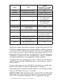 2
2
-
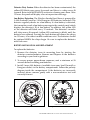 3
3
-
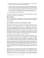 4
4
-
 5
5
-
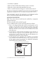 6
6
-
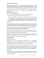 7
7
-
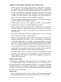 8
8
-
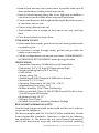 9
9
-
 10
10
-
 11
11
-
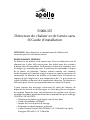 12
12
-
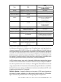 13
13
-
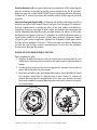 14
14
-
 15
15
-
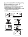 16
16
-
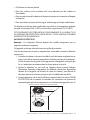 17
17
-
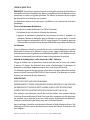 18
18
-
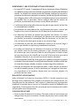 19
19
-
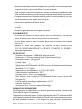 20
20
-
 21
21
-
 22
22


Apollo 51000-355 Guide d'installation
- Catégorie
- Protection contre le feu
- Taper
- Guide d'installation
dans d''autres langues
- English: Apollo 51000-355 Installation guide
Documents connexes
Autres documents
-
QOLSYS QS5110-840 IQSmoke Wireless Smoke Heat Alarm Le manuel du propriétaire
-
Risco RWX35S Installation and User Manual
-
Chacon 34953 Manuel utilisateur
-
Otio 520045 Le manuel du propriétaire
-
QOLSYS QS5210-840 Guide d'installation
-
SimpliSafe SSSD3 Manuel utilisateur
-
System Sensor Limitations of Fire Alarm Systems Manuel utilisateur
-
 DMP 277 Trouble Annunciator Guide d'installation
-
Support Honeywell ADT 2X16AIO Home Security Panel Guide d'installation
-
 Onelink 1042136 Manuel utilisateur

