Lorex LZV2925B-2PK Manuel utilisateur
- Catégorie
- Des caméras de sécurité
- Taper
- Manuel utilisateur
Ce manuel convient également à

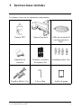
Instructional
Manual
LZV2925 1080p
MPX PTZ
Camera

Thank you for purchasing this product. Lorex Corporation is committed
to providing our customers with a high quality, reliable security solution.
This manual refers to the following models:
LZV2925
For the latest online manual, downloads and product updates, and to
learn about our complete line of accessory products, please visit our
website at:
www.lorextechnology.com
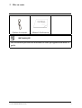
WARNING
RISK OF ELECTRIC
SHOCK
DO NOT OPEN
WARNING: TO REDUCE THE RISK OF ELECTRIC
SHOCK DO NOT REMOVE COVER. NO USER
SERVICEABLE PARTS INSIDE.
REFER SERVICING TO QUALIFIED SERVICE
PERSONNEL.
#; r. 9.0/56187/56187; en-US

The lightning flash with arrowhead symbol,
within an equilateral triangle, is intended to
alert the user to the presence of uninsulated
"dangerous voltage" within the product’s
enclosure that may be of sufficient magnitude
to constitute a risk of electric shock.
The exclamation point within an equilateral
triangle is intended to alert the user to the
presence of important operating and
maintenance (servicing) instructions in the
literature accompanying the appliance.
WARNING: TO PREVENT FIRE OR SHOCK HAZARD,
DO NOT EXPOSE THIS UNIT TO RAIN OR
MOISTURE.
CAUTION: TO PREVENT ELECTRIC SHOCK, MATCH
WIDE BLADE OF THE PLUG TO THE WIDE SLOT
AND FULLY INSERT.
#; r. 9.0/56187/56187; en-US

Table of contents
1 Safety Instructions . . . . . . . . . . . . . . . . . . . . . . . . . . . . . . . . . . . . . . . . . . . 1
2 Getting Started . . . . . . . . . . . . . . . . . . . . . . . . . . . . . . . . . . . . . . . . . . . . . . . 2
3 Connecting the Camera . . . . . . . . . . . . . . . . . . . . . . . . . . . . . . . . . . . . . . 4
3.1 Video Cabling (Professional Installations
Only) . . . . . . . . . . . . . . . . . . . . . . . . . . . . . . . . . . . . . . . . . . . . . . . 5
3.2 Power Cabling (Professional Installations
Only) . . . . . . . . . . . . . . . . . . . . . . . . . . . . . . . . . . . . . . . . . . . . . . . 7
4 Installation . . . . . . . . . . . . . . . . . . . . . . . . . . . . . . . . . . . . . . . . . . . . . . . . . . . 8
4.1 Installation Tips & Warnings . . . . . . . . . . . . . . . . . . . . . . . . 8
4.2 Installation (Indoor / Outdoor) . . . . . . . . . . . . . . . . . . . . . . 9
5 Controlling the PTZ Camera with a Lorex MPX
DVR . . . . . . . . . . . . . . . . . . . . . . . . . . . . . . . . . . . . . . . . . . . . . . . . . . . . . . . . . 13
5.1 Controlling a PTZ Camera (Local
DVR) . . . . . . . . . . . . . . . . . . . . . . . . . . . . . . . . . . . . . . . . . . . . . . 13
5.2 Advanced PTZ Controls. . . . . . . . . . . . . . . . . . . . . . . . . . . . 15
6 Changing PTZ Protocol and Video Format . . . . . . . . . . . . . . . . . 21
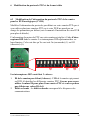
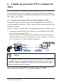
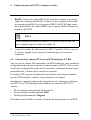
6.1 Connecting the PTZ Camera to an Analog
DVR (CVBS) . . . . . . . . . . . . . . . . . . . . . . . . . . . . . . . . . . . . . . 21
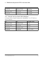
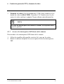
6.2 Controlling the PTZ Camera with an Analog
DVR (CVBS) . . . . . . . . . . . . . . . . . . . . . . . . . . . . . . . . . . . . . . 22
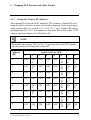
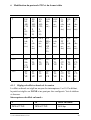
6.3 Changing the Camera’s PTZ Protocol
Information for Analog DVRs (CVBS) . . . . . . . . . . . . . 23
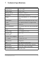
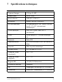
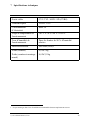
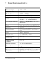
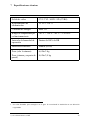
7 Technical Specifications . . . . . . . . . . . . . . . . . . . . . . . . . . . . . . . . . . . . . 27
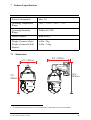
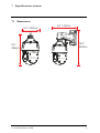
7.1 Dimensions . . . . . . . . . . . . . . . . . . . . . . . . . . . . . . . . . . . . . . . . 28
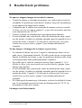
8 Troubleshooting . . . . . . . . . . . . . . . . . . . . . . . . . . . . . . . . . . . . . . . . . . . . . 29
#; r. 9.0/56187/56187; en-US vii

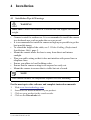
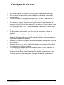
1 Safety Instructions
• Read this guide carefully and keep it for future reference.
• Follow all instructions for safe use of the product and handle with care.
• Use the camera within given temperature, humidity, and voltage levels
noted in the Technical Specifications.
• Camera is rated for outdoor use and is weatherproof when properly in-
stalled. Camera is not intended for submersion in water. Installation
under a sheltered environment is recommended.
• Do not disassemble the camera.
• Do not point the camera directly towards the sun or a source of intense
light.
• Use only the supplied regulated power supply. Use of a non-regulated,
non-conforming power supply can damage this product and voids the
warranty.
• Make sure to install the camera in a location that can support the camera
weight.
• Make sure there are no live electrical cables in the area where you plan
to mount the camera.
• Periodic cleaning may be required. Use a damp cloth only. Do not use
anything other than water to clean the dome cover, as chemicals such as
acetone can permanently damage the plastic.
#; r. 9.0/56187/56187; en-US 1


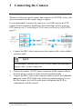
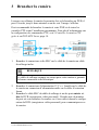
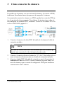
3 Connecting the Camera
When you first power up the camera and connect it to the DVR, it may take
up to two minutes for the camera image to appear.
It is recommended to connect the camera to your DVR and test the PTZ
controls before permanent installation. For instructions on how to set up
PTZ controls, see 5 Controlling the PTZ Camera with a Lorex MPX DVR,
page 13.
1. Connect the BNC video connector on the camera cable to the included
extension cable.
NOTE
The included extension cable is built for this camera and guarantees
proper video / power connection.
2. Connect the female 12V DC power connector on the camera cable to
the male power connector on the included extension cable.
3. Connect the BNC cable on the extension cable to one of the Video In-
put ports on the DVR. Make note of the port number where you con-
nect the camera, as it will be used when configuring the DVR to
communicate with the camera.
#; r. 9.0/56187/56187; en-US 4

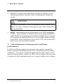
3 Connecting the Camera
4. Connect the power connector on the extension cable to the included
power adapter. Plug the power adapter into a power outlet.
CAUTION
Make sure to disconnect the power adapter before installing the
camera. The camera will begin moving immediately when the
power adapter is connected.
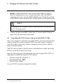
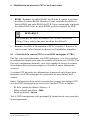
5. RS485: Only for use with analog DVRs (CVBS) — To control the
camera’s PTZ functions, connect the camera’s RS485 cables to the
DVR’s RS485 ports. Match the polarity of the RS485 cables with the
DVR’s RS485 positive and negative ports. See 6 Changing PTZ Proto-
col and Video Format, page 21 for full details.
3.1 Video Cabling (Professional Installations Only)
The included extension cable is built for this camera and guarantees proper
video / power connection. For professional installations only — You can ex-
tend the video signal from this camera using a single extension cable be-
tween the camera and the DVR. See the table below for the maximum cable
run lengths for all supported cable types:
#; r. 9.0/56187/56187; en-US 5

3 Connecting the Camera
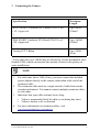
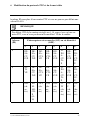
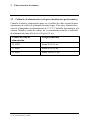
Specification Maximum
Length
RG59 20AWG Conductor 95% Braid CSA/UL or C
(UL) Approved
1
Up to 985ft
(300m)*
RG6 20AWG Conductor 95% Braid CSA/UL or C
(UL) Approved
1
Up to 1640ft
(500m)*
Analog CCTV Balun Up to 300ft
(91m)
* Long cable runs over 1000ft may be affected by electro-mechanical inter-
ference (EMI), which can increase the amount of noise in the picture in
some installations.
NOTE
1. For cable runs above 300ft (91m), you must connect the included
power adapter directly to the camera, rather than at the end of the
extension cable.
2. The extension cable must be a single stretch of cable between the
recorder and camera. You cannot connect multiple extension cables
to each other.
3. Indicators that your cable run may be too long:
• Video is permanently black & white (even during day time)
• Video is unclear, soft, or distorted
4. For more information on extension cables, visit
www.lorextechnology.com/support
#; r. 9.0/56187/56187; en-US 6

3 Connecting the Camera
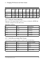
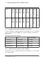
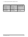
3.2 Power Cabling (Professional Installations Only)
See the table below for required cable gauge for longer power cable runs.
For other installations, connect the included 12V DC power adapter directly
to the camera. Due to voltage drops, it is not recommended to extend power
cabling beyond 100ft (31m).
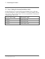
Power Cable Gauge Maximum Length
18AWG Up to 50ft (15m)
17AWG Up to 60ft (18m)
15AWG Up to 100ft (31m)
#; r. 9.0/56187/56187; en-US 7

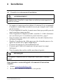
4 Installation
4.1 Installation Tips & Warnings
WARNING
Make sure to install the camera in a location that can support the camera
weight.
• Camera is rated for outdoor use. It is recommended to install the camera
in a sheltered area, such as under the eaves on a roof.
• It is recommended to install the camera as high up as possible to get the
best possible image.
• To extend the length of the cable, see 3.1 Video Cabling (Professional
Installations Only), page 5.
• Mount the camera where the lens is away from direct and intense
sunlight.
• Plan your cable wiring so that it does not interfere with power lines or
telephone lines.
• Ensure you adhere to local building codes.
• Ensure that the camera wiring is not exposed or easily cut.
• Mount the camera in an area that is visible but out of reach.
NOTE
This camera includes all components required for wall mounting.
For the most up-to-date software and complete instruction manuals:
1. Visit www.lorextechnology.com.
2. Search for the model number of your product.
3. Click on your product in the search results.
4. Click on the Downloads tab.
#; r. 9.0/56187/56187; en-US 8

4 Installation
4.2 Installation (Indoor / Outdoor)
CAUTION
• Make sure to disconnect the power cable before installing the cam-
era. Camera will begin moving immediately when power cable is
connected.
• Make sure to install the camera in a location that can support the
camera weight.
To install the camera on a wall:
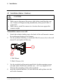
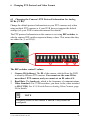
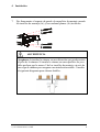
1. Attach the included rubber ring to the back of the wall mount to ensure
the weatherproof rating of the camera.
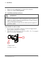
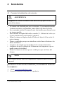
2. Use the included Allen key to attach the M6x14 screws (3x) to the wall
mount. Do not tighten all the way.
2
1
1. Wall Mount
2. M6x14 Screws (3x)
3. Use the included wall mount to mark holes for the mounting screws
(4x) and cables. Drill holes (drill bit size – 3/8”) to a depth of 2.8”/
70mm in the mounting surface where marked.
4. Insert the included anchors (4x) into the holes and tap them into the
wall with a hammer.
#; r. 9.0/56187/56187; en-US 9

4 Installation
5. Pull the connection cable(s) through the mounting surface and wall
mount.
6. Attach the included flat washers (4x) to the included mounting screws
(4x).
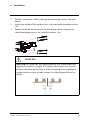
7. Firmly attach the wall mount to the mounting surface using the in-
cluded mounting screws (4x) and flat washers (4x).
WARNING
Make sure to install the wall mount bracket in a location that can
support the camera’s weight. If mounting the camera on a drywall
surface, you must drill at least 2 of the mounting screws through a
wooden stud to ensure a stable mount. See the diagram below for
details.
#; r. 9.0/56187/56187; en-US 10

4 Installation
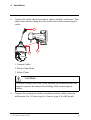
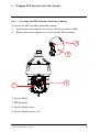
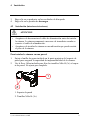
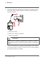
8. Connect the safety chain between the camera and the wall mount. This
allows the camera to hang from the wall mount while connecting the
cables.
1
3
2
1. Camera Cables
2. Safety Chain Hook
3. Safety Chain
CAUTION
You must connect the safety chain between the camera and the wall
mount to protect the camera from falling while connecting the
cables.
9. Connect the connection cable(s) and then push the cable(s) into the
wall mount. See 3 Connecting the Camera, page 4 for full details.
#; r. 9.0/56187/56187; en-US 11

4 Installation
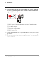
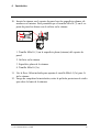
10. Push the camera into the wall mount with the flat surfaces aligned on
the inside. This will allow the M6x14 screw (1) on the wall mount to
align with the hole on the camera.
2
3
4
1
1. M6x14 screw (1) on the flat surface (inside) of the wall mount.
2. Hole on the camera.
3. Flat surface on the camera.
4. M6x14 screw (2x).
11. Use the included Allen key to tighten the M6x14 screw (3x) to secure
the camera.
12. Remove protective vinyl sheet covering the camera lens once installa-
tion is completed.
#; r. 9.0/56187/56187; en-US 12

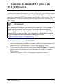
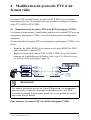
5 Controlling the PTZ Camera with a
Lorex MPX DVR
You can connect the PTZ camera to a Lorex MPX DVR to control the cam-
era’s movement. Lorex MPX PTZ cameras can accept PTZ commands di-
rectly through the coaxial video cable. There is no need to run RS485
wiring to use Lorex MPX PTZ cameras.
NOTE
The following instructions are based on the LHV Series DVRs. See your
DVR’s instruction manual for instructions on controlling the PTZ cam-
era with your system. For the latest list of compatible DVRs, please visit
www.lorextechnology.com/compatibility.
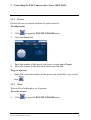
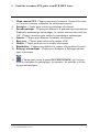
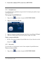
5.1 Controlling a PTZ Camera (Local DVR)
1. In Live View, click the channel that has the PTZ camera connected to
open in full-screen.
2. Right-click and click Pan/Tilt/Zoom. Enter the system user name and
password if prompted. The PTZ menu opens.
3. Use the on-screen PTZ controls to control the camera.
#; r. 9.0/56187/56187; en-US 13

5 Controlling the PTZ Camera with a Lorex MPX DVR
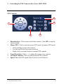
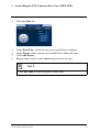
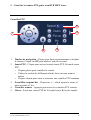
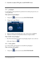
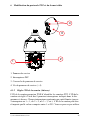
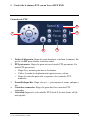
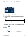
PTZ Controls
1
2
3
5
4
1. Direction keys: Click to pan and tilt the camera. Click SIT to stop the
current action.
2. Mouse PTZ: Click to activate mouse PTZ mode. In mouse PTZ mode:
• Click and drag to move the camera.
• Use the scroll wheel to zoom in and out.
• Right-click to exit and return to normal PTZ controls.
3. Zoom/Focus/Iris: Click + / - to adjust the zoom, focus, and iris.
4. Advanced controls: Click to open advanced PTZ controls.
5. Speed: Enter the PTZ speed from 1 (slowest) to 8 (fastest).
#; r. 9.0/56187/56187; en-US 14

5 Controlling the PTZ Camera with a Lorex MPX DVR
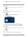
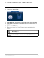
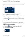
5.2 Advanced PTZ Controls
Advanced PTZ controls can be used to save camera positions and cycle
through various positions, and automate camera actions.
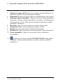
To open advanced PTZ controls:
• Click the arrow in the PTZ control window to open advanced controls.
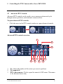
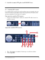
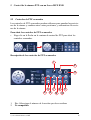
Advanced PTZ controls overview:
10
8
6
4
5
7
9
11
1
2
3
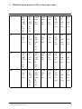
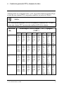
1. No.: Select the number of the action you want to perform.
2. Not supported.
3. PTZ camera menu: Click to open the camera’s OSD menu. This menu
is for advanced users only.
#; r. 9.0/56187/56187; en-US 15

5 Controlling the PTZ Camera with a Lorex MPX DVR
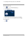
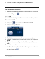
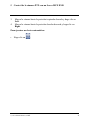
4. Preset: Click to call the selected preset.
5. AutoPan: Click to start autopan. During autopan, the camera will con-
tinuously pan 360°. Click again to stop auto pan.
6. Tour: Click to run the selected tour.
7. Flip: Click to flip the camera 180°.
8. Pattern: Click to run the selected pattern.
9. Reset: Click to move the camera to the home position.
10. Auto Scan: Click to run the selected autoscan.
11.
: Click to open the PAN/TILT/ZOOM menu, where you can set
up Presets, Tours, Patterns, and Auto Scans.
#; r. 9.0/56187/56187; en-US 16
La page est en cours de chargement...
La page est en cours de chargement...
La page est en cours de chargement...
La page est en cours de chargement...
La page est en cours de chargement...
La page est en cours de chargement...
La page est en cours de chargement...
La page est en cours de chargement...
La page est en cours de chargement...
La page est en cours de chargement...
La page est en cours de chargement...
La page est en cours de chargement...
La page est en cours de chargement...
La page est en cours de chargement...
La page est en cours de chargement...
La page est en cours de chargement...
La page est en cours de chargement...
La page est en cours de chargement...
La page est en cours de chargement...
La page est en cours de chargement...
La page est en cours de chargement...
La page est en cours de chargement...
La page est en cours de chargement...
La page est en cours de chargement...
La page est en cours de chargement...
La page est en cours de chargement...
La page est en cours de chargement...
La page est en cours de chargement...
La page est en cours de chargement...
La page est en cours de chargement...
La page est en cours de chargement...
La page est en cours de chargement...
La page est en cours de chargement...
La page est en cours de chargement...
La page est en cours de chargement...
La page est en cours de chargement...
La page est en cours de chargement...
La page est en cours de chargement...
La page est en cours de chargement...
La page est en cours de chargement...
La page est en cours de chargement...
La page est en cours de chargement...
La page est en cours de chargement...
La page est en cours de chargement...
La page est en cours de chargement...
La page est en cours de chargement...
La page est en cours de chargement...
La page est en cours de chargement...
La page est en cours de chargement...
La page est en cours de chargement...
La page est en cours de chargement...
La page est en cours de chargement...
La page est en cours de chargement...
La page est en cours de chargement...
La page est en cours de chargement...
La page est en cours de chargement...
La page est en cours de chargement...
La page est en cours de chargement...
La page est en cours de chargement...
La page est en cours de chargement...
La page est en cours de chargement...
La page est en cours de chargement...
La page est en cours de chargement...
La page est en cours de chargement...
La page est en cours de chargement...
La page est en cours de chargement...
La page est en cours de chargement...
La page est en cours de chargement...
La page est en cours de chargement...
La page est en cours de chargement...
La page est en cours de chargement...
La page est en cours de chargement...
La page est en cours de chargement...
La page est en cours de chargement...
La page est en cours de chargement...
La page est en cours de chargement...
La page est en cours de chargement...
La page est en cours de chargement...
La page est en cours de chargement...
La page est en cours de chargement...
La page est en cours de chargement...
La page est en cours de chargement...
La page est en cours de chargement...
La page est en cours de chargement...
La page est en cours de chargement...
La page est en cours de chargement...
La page est en cours de chargement...
La page est en cours de chargement...
La page est en cours de chargement...
La page est en cours de chargement...
La page est en cours de chargement...
La page est en cours de chargement...
La page est en cours de chargement...
La page est en cours de chargement...
La page est en cours de chargement...
La page est en cours de chargement...
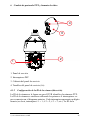
-
 1
1
-
 2
2
-
 3
3
-
 4
4
-
 5
5
-
 6
6
-
 7
7
-
 8
8
-
 9
9
-
 10
10
-
 11
11
-
 12
12
-
 13
13
-
 14
14
-
 15
15
-
 16
16
-
 17
17
-
 18
18
-
 19
19
-
 20
20
-
 21
21
-
 22
22
-
 23
23
-
 24
24
-
 25
25
-
 26
26
-
 27
27
-
 28
28
-
 29
29
-
 30
30
-
 31
31
-
 32
32
-
 33
33
-
 34
34
-
 35
35
-
 36
36
-
 37
37
-
 38
38
-
 39
39
-
 40
40
-
 41
41
-
 42
42
-
 43
43
-
 44
44
-
 45
45
-
 46
46
-
 47
47
-
 48
48
-
 49
49
-
 50
50
-
 51
51
-
 52
52
-
 53
53
-
 54
54
-
 55
55
-
 56
56
-
 57
57
-
 58
58
-
 59
59
-
 60
60
-
 61
61
-
 62
62
-
 63
63
-
 64
64
-
 65
65
-
 66
66
-
 67
67
-
 68
68
-
 69
69
-
 70
70
-
 71
71
-
 72
72
-
 73
73
-
 74
74
-
 75
75
-
 76
76
-
 77
77
-
 78
78
-
 79
79
-
 80
80
-
 81
81
-
 82
82
-
 83
83
-
 84
84
-
 85
85
-
 86
86
-
 87
87
-
 88
88
-
 89
89
-
 90
90
-
 91
91
-
 92
92
-
 93
93
-
 94
94
-
 95
95
-
 96
96
-
 97
97
-
 98
98
-
 99
99
-
 100
100
-
 101
101
-
 102
102
-
 103
103
-
 104
104
-
 105
105
-
 106
106
-
 107
107
-
 108
108
-
 109
109
-
 110
110
-
 111
111
-
 112
112
-
 113
113
-
 114
114
-
 115
115
-
 116
116


Lorex LZV2925B-2PK Manuel utilisateur
- Catégorie
- Des caméras de sécurité
- Taper
- Manuel utilisateur
- Ce manuel convient également à
dans d''autres langues
- English: Lorex LZV2925B-2PK User manual
- español: Lorex LZV2925B-2PK Manual de usuario
Documents connexes
-
Lorex MPX168AW Guide de démarrage rapide
-
Lorex MPX168W Guide de démarrage rapide
-
-
Lorex LEV2522PK2BW Guide de démarrage rapide
-
-
-
Lorex LZV2622BW Series Manuel utilisateur
-
-
-
Lorex MPX0616W Guide de démarrage rapide
Autres documents
-
FLIR C346ZC252 Manuel utilisateur
-
-
Swann SW331-PR6 Operating Instructions Manual
-
-
Lorex Technology L15LD420 Series Manuel utilisateur
-
-
Swann vPRO-650 Mode d'emploi
-
Eneo DLR5-16 Quick Installation Manual
-
-