Weidmueller 2682600000 Guide d'installation
- Taper
- Guide d'installation

1 2 3
Hardware Installation Guide
Serial/Ethernet Converter / Modbus Gateway
IE-CS-MBGW-2TX-1COM (Part No. 2682600000)
1. Introduction
Device IE-CS-MBGW-2TX-1COM is a multi-purpose Serial/Ethernet converter and Modbus
TCP/RTU-ASCII protocol gateway and is equipped with one configurable RS232/422/485 port
and two Ethernet RJ45 ports (acting like an unmanaged 2-Port switch).
If configured as Serial/Ethernet converter it can be used to convert data streams between
serial and Ethernet networks. The converter supports standard device server features like
Virtual COM Mode, TCP Server/Client or UDP Server/Client operation modes.
Running as Modbus protocol gateway it can be used to convert data streams between
protocols Modbus TCP (Ethernet) and Modbus ASCII/RTU (serial-based). The device
supports the operation modes “ASCII/RTU Master to TCP Slave Gateway” and “TCP Master
to ASCII/RTU Slave Gateway”.
The devices are designed for industrial applications and fitted with a robust housing. To
ensure reliable, error-free operation, and to prevent damage or injury, please read the
operating instructions, all safety information provided in this document and any other safety
information that were supplied with the product.
2. Safety notice
The device heats up during operation. Allow the unit to cool down or use protection
gloves when carrying out any work.
The device may only be connected to the supply voltage shown on the product label.
Higher voltage than specified will destroy the device.
The device must be supplied by a SELV source as defined in the Low Voltage
Directive 2014/35/EU and 2014/30/EU.
Installation, commissioning and maintenance may only be performed by qualified
electricians.
Observe the operating instructions.
Indoor use and pollution degree II, it must be wiped with a dry cloth for clean up
the device and label.
o Utilisation en intérieur et degré de pollution II, il faut l'essuyer avec un chiffon sec
pour nettoyer l'appareil et son étiquette.
Do not block air ventilation holes.
o Ne bouchez pas les orifices de ventilation.
If the equipment is used in a manner not specified by the manufacturer, the
protection provided by the equipment may be impaired.
o Si l’appareil est utilise d’une maniere non specifiee par le fabricant, la protection
qu’il apporte peut se voir diminuee.
Shall be mounted in the Industrial Control Panel and ambient temperature is not
exceed 70 degrees C.
o Doit être monté dans le panneau de commande industriel et la température
ambiante ne doit pas dépasser 70 degrés C.
Intended use: The device is intended for the realization of communication networks within an
industrial environment, it is intended to be used in a restricted access location. The device may only
be used within the scope of the specified technical data. The device is intended to be mounted to a
well-grounded mounting surface, such as a metal panel. Any other use may result in unintentional
malfunction and damage. Observing the documentation is part of the intended use.
Environmental conditions: This equipment is intended to be used in a restricted access location.
When planning the installation site make sure that the ambient temperature during operation will not
exceed the temperature given in the technical data.
Also make sure that the air flow will not be compromised by other devices.
Ensure that the mounted and wired device is not exposed to any mechanical stress.
FCC compliance: This device complies with part 15 of FCC Rules. Operation is subject to the
following two conditions: (1) This device may not cause harmful interference, and (2) this device must
accept any interference received, including interference that may cause undesired operation.
3. Package Checklist
1 x Serial/Ethernet-Converter/Modbus-Gateway 1 x Hardware Installation Guide
1 x 4-Pin Terminal connector 1 x Wall mounting kit
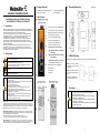
4. Panel Layouts
1. Terminal block for power input PWR1/PWR2
2. Grounding screw / Frame ground (Note: The
shielding ground of the LAN port is electrically
connected to the grounding screw)
3. Power input LEDs (PWR1 / PWR2)
4. Link/Activity LEDs Ethernet Ports
5. Data Transmission LEDs Serial Port
6. Serial Port (DB9 male Connector)
7. DIP Switches for serial line settings
SW1: Sets Pull-Up resistor to 1 KΩ (ON) or
150 KΩ (OFF).
SW2: Sets Pull-Down resistor to 1 KΩ (ON)
or 150 KΩ (OFF).
SW3: Enables / Disables Line Termination.
By factory default all DIP switches are set to OFF.
8. Ethernet RJ45 Ports 10/100BASE-T(X)
9. Article Number
10. Reset Button
11. DIN-rail kit
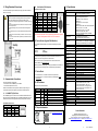
5. Mounting Dimensions (units = mm)
6. DIN-Rail Mounting
Slide the device onto DIN-rail and make sure that the Din-rail clip clicks into the rail firmly.
STEP 1: Insert the top of the DIN-
Rail into the slot just below the stiff
metal spring.
STEP 2: The DIN-Rail attachment
unit will snap into place as shown
below.
To remove the device from the
DIN-rail simply reverse steps 1
and 2.
7. Grounding
ATTENTION
- Grounding and wire routing help limit the effects of noise due to
electromagnetic interference (EMI).
- Do the ground connection from the ground screw to the grounding
surface prior to connecting devices.
- This product is intended to be mounted to a well-grounded mounting
surface, such as a metal panel.
- The shielding ground of the RJ45 ports are electrically connected to the
ground connection (screw).

4 5 6 V1.4.1 / 2022-04-02
8. Wiring Redundant Power Inputs
The Converter/Gateway supports redundant power supply inputs. Refer to illustration
below for correct wiring.
Warning / Avertissement
Take into consideration the following guidelines before wiring the device
o Tenez compte des directrices suivantes avant de câbler l’appareil.
Terminal block is mating with Plug and suitable for 12-24AWG. Torque value
4.5 lb-in.
o Le bornier est compatible avec les connecteurs et convient pour 12-24AWG.
Valeur de couple 4,5 lb-in.
The temperature rating of the input connection cable should higher than
105°C.
o La température de service nominale du câble d’entrée doit être supérieure à
105 °C.
Supplied by SELV source evaluated by UL 61010-1 or 61010-2-201 power
supply only.
o Fourni par la source SELV évaluée uniquement par l'alimentation UL 61010-1
or 61010-2-201.
9. Communication Connections
The Converter/Gateway is equipped with:
2 x RJ45 Ethernet Port 10/100BASE-T(X) / Auto MDI-X
1 x Serial Interface (DB9 male connector)
Please use for RJ45 Ethernet Ports only cables suitable for the respective type of
communication and ensure that signals are protected from possible interference.
9.1 10/100BASE-T(X) RJ45 Ports
The 10/100BASE-T(X) ports are used to connect to Ethernet-enabled devices. Below
table shows pinouts for both MDI (NIC-type) ports and MDI-X (HUB/Switch-type) ports.
Auto MDI-X ensures that both wiring-schemes are supported (Automatic crossover).
10/100BASE-T(X) RJ45 Pinouts
MDI Port Pinouts
MDI
-
X Port Pinouts
8
-
pin RJ45
Pin
Signal
Pin
Signal
1
Tx+
1
Rx+
2
Tx
-
2
Rx
-
3
Rx+
3
Tx+
6
Rx
-
6
Tx
-
9.2 Serial Interface DB-9 Connector
Pinouts DB-9 Connector (male)
1) Note: Table with correct pinouts for RS-422 and RS-485 4-wire interface modes. In previous
document V1.3 the assignments for RX-/RX+ and TX-/TX+ were reversed!
10. Device Access (Login to Web Interface)
For configuration the Web interface can be accessed via following factory default
settings:
IP address / Netmask: 192.168.1.110 / 255.255.255.0
Username: admin
Password: Weidmueller
Connect the PC to any Ethernet port of the Converter/Gateway and set the PC’s IP
address to a free one of range 192.168.1.0 / 255.255.255.0
Start a web browser and enter the IP address of the connected device into the
browser’s address line (http://192.168.1.110).
After the appearance of prompt (login) enter the login credentials. After confirmation of
your input with "OK" the home page of the Converter/Gateway will be displayed.
11. Device Reset
Press reset button for < 5 seconds to reboot the device (Warm Start).
Press reset button for >= 5 seconds to reset the Converter/Gateway to factory
default settings.
12. LED Indicators
Description of front panel LED indicators:
LED Color Status Description
PWR1 Green On Power is supplied to power input PWR1.
PWR2 Green On Power is supplied to power input PWR2.
Eth1 Green On Ethernet Port 1 is connected.
Blinking Data is transmitted.
Eth2 Green On Ethernet Port 2 is connected.
Blinking Data is transmitted.
Rx Amber On Receiving serial data.
Tx Green On Transmitting serial data.
13. Disposal information
Observe the notes for proper disposal of the product. You
can find the notes here: www.weidmueller.com/disposal.
14. Specifications
Interfaces
Ethernet Ports 2 x RJ45 10/100BASE-T(X) auto negotiation speed, F/H
duplex mode and auto MDI/MDI-X connection
Serial Port
1x DB9 connector (male)
Interface Settings RS-232/422/485
Baud Rates 110 bps to 460800 bps
Data Bits 7, 8
Parity odd, even, none, mark, space
Stop Bits 1, 2
RS-232: TxD, RxD, RTS, CTS, DTR, DSR, DCD, GND
RS-422: Rx-, Rx+, Tx+, Tx-, GND
RS-485 4 wire: Rx-, Rx+, Tx+, Tx-, GND
RS-485 2 wire: Data-, Data+, GND
Flow Control XON/XOFF, RTS/CTS, DTR/DSR
LED Indicators
PWR 1 / 2 (Power supply)
Eth 1 / 2 (Ethernet Port Link / Activity)
Tx / Rx (Serial Port Data Transmit / Receive)
DIP Switch
SW1: Sets Pull-Up resistor to 1 KΩ (ON) or 150 Ω (OFF)
SW2: Sets Pull-Down res. to 1 KΩ (ON) or 150 KΩ (OFF)
SW3: Enables (ON) / Disables (OFF) Line Termination
Power supply
Input Voltage 24 V DC (12 to 48 V DC), 2 redundant inputs
Current Consumption 0.05 A – 0.1 A
Connection One removable 4-pin terminal block, Wiring cable 12-
24AWG
Overload Current
Protection Present
Reverse Polarity
Protection Present
Physical Characteristics
Housing IP30 protection, metal
Dimension (W x H x D) 26.1 x 110 x 75.2 mm (1.02 x 4.33 x 2.95 inch)
Weight 200 g
Installation DIN-rail, Wall
Environmental conditions
Operating Temperature -40 to 70°C (-40 to 158°F)
Storage Temperature -40 to 85°C (-40 to 185°F)
Ambient Relative Humidity
5 to 95% (non-condensing)
Altitude up to 2000 m
Regulatory Approvals
Safety UL 61010-1; UL 61010-2-201
EMC
EN 55032, EN 55024, FCC Part 15 Subpart B Class A,
IEC 61000-4-2 ESD: Contact: 4 kV; Air: 8 kV,
IEC 61000-4-3 RS: 80 MHz bis 1 Ghz: 3 V/m,
IEC 61000-4-4 EFT: Power: 0.5 kV; Signal: 0.5 kV,
IEC 61000-4-5 Surge: Power: 0,5 kV; Signal: 1 kV,
IEC 61000-4-6 CS: 3 Vrms
Shock IEC 60068-2-27
Free Fall IEC 60068-2-31
Vibration IEC 60068-2-6
MTBF
Time 1.479.078 hrs
Database Telcordia SR332
Warranty
Time Period 5 years
Contact Information
Weidmüller Interface GmbH & Co. KG
Klingenbergstraße 26, 32758 Detmold / Germany
Phone +49 (0) 5231 14-0, Fax +49 (0) 5231 14-292083
E-Mail weidmueller@weidmueller.com, Internet www.weidmueller.com
Pin # RS-232
(DTE Device) RS-4221) RS-485
1)
(4
-
wire)
RS-485
(2-wire)
1
DCD
R
X
-
R
X
-
DATA
-
2
RXD
R
X+
R
X+
DATA+
3
TXD
T
X+
T
X+
---
4
DTR
T
X
-
T
X
-
---
5
GND
GND
GND
GND
6
DSR
---
---
---
7
RTS
---
---
---
8
CTS
---
---
---
9
RI
---
---
---
-
 1
1
-
 2
2


Weidmueller 2682600000 Guide d'installation
- Taper
- Guide d'installation
dans d''autres langues
Autres documents
-
 KYLAND Technology KPS3102 Series Hardware Installation Manual
-
Moxa EDS-510E Series Guide d'installation rapide
-
-
Adlink EMU-200 Series Le manuel du propriétaire
-
Sixnet IPm Guide d'installation
-
red lion ST Manuel utilisateur
-
-
 ANTAIRA LMX-0702G-SFP-V2 Series Manuel utilisateur
-
-

