Pleasant Hearth 24-900-001 Homeowner's Installation And Operating Instructions Manual
- Catégorie
- Chauffe-eau
- Taper
- Homeowner's Installation And Operating Instructions Manual
Ce manuel convient également à

1
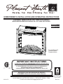
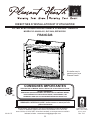
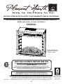
HOMEOWNER’S INSTALLATION AND OPERATING INSTRUCTIONS
PLEASANT HEARTH ELECTRIC FIREPLACE INSERT
MODEL/MODELE/MODELO #24-900-001, GLF-2404, GEF24CRG11
For installation with
Pleasant Hearth
Fireplace Mantel
Questions, problems, missing parts? Before returning to your retailer, call our customer
service department at 877-447-4768 8:30 a.m. – 4:30 pm CST, Monday – Friday.
or email us at [email protected]
20-10-175 Rev.7/13
C US
INSTALLER: Leave this manual with the appliance.
CONSUMER: Retain this manual for future reference.
WARNING!
IF THE INFORMATION IN THIS MANUAL IS NOT FOLLOWED EXACTLY,
AN ELECTRICAL SHOCK OR FIRE MAY RESULT
CAUSING PROPERTY DAMAGE, PERSONAL INJURY OR LOSS OF LIFE.
IMPORTANT INSTRUCTIONS
PLEASE READ THIS MANUAL BEFORE INSTALLING AND USING APPLIANCE
Français p. 19
Español p. 38
6440 W. Howard St.
Niles, IL 60714-3302
877-447-4768

2
IMPORTANT: Read all instructions and warnings carefully before starting Installation.
Failure to follow these instructions may result in a possible electric shock, injury to
persons, re hazard and will void the warranty.
Please read the Installation & Operating Instructions before using this appliance.
TABLE OF CONTENTS
Safety Information ............................................................................................................................3
Installation Instructions ..................................................................................................................... 6
Operation Instructions .................................................................................................................... 10
Care and Maintenance ................................................................................................................... 13
Electric Wiring Diagram ..................................................................................................................14
Troubleshooting .............................................................................................................................. 15
Warranty ......................................................................................................................................... 16
Replacement Parts List .................................................................................................................. 17
Thank you and congratulations on your purchase of a
GHP Group electric replace.

3
Please read and understand this entire manual before attempting to assemble, operate or install
the product. If you have any questions regarding the product, please call customer service at
1-877-447-4768, 8:30 a.m. – 4:30 p.m., CST, Monday – Friday.
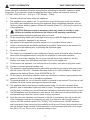
1. Read all instructions before using this appliance.
2. This appliance is hot when in use. To avoid burns, do not let bare skin touch hot surfaces.
If provided, use handles when moving this appliance. Keep combustible materials, such as
furniture, pillows, bedding, papers, clothes and curtains at least 3 ft. (914 mm) from the front
of this appliance.
3. CAUTION: Extreme caution is necessary when any heater is used by or near
children or invalids and whenever the heater is left operating unattended.
4. If possible always unplug this appliance when not in use.
5. Do not operate any heater with a damaged cord or plug or after the appliance malfunctions,
has been dropped or damaged in any manner.
6. Anyrepairstothisapplianceshouldbecarriedoutbyaqualiedserviceperson.
7. Undernocircumstancesshouldthisappliancebemodied.Partshavingtoberemovedfor
servicing must be replaced prior to operating this appliance again.
8. Do not use outdoors.
9. This heater is not intended for use in bathrooms, laundry areas and similar indoor locations.
Never place this appliance where it may fall into a bathtub or other water container.
10. Do not run cord under carpeting. Do not cover cord with throw rugs, runners or the like.
Arrangecordawayfromtrafcareasandwhereitwillnotbetrippedover.
11. To disconnect this appliance, turn controls to the off position, then remove plug from outlet.
12. Connect to properly grounded outlets only.
13. This appliance, when installed must be electrically grounded in accordance with local codes,
with the current CSA C22.1 Canadian Electrical codes or for USA installations, follow local
codes and the National Electric Code, ANSI/NFPA No. 70.
14. Do not insert or allow foreign objects to enter any ventilation or exhaust opening as this may
causeanelectricshock,reordamagetheappliance.
15. Topreventpossiblere,donotblockairintakesorexhaustinanymanner.Donotuseonsoft
surfaces, like a bed, where openings may become blocked.
16. This appliance has hot and arcing or sparking parts inside. Do not use it in areas where
gasoline,paintorammableliquidsareusedorstored.Thisapplianceshouldnotbeusedas
a drying rack for clothing, nor should Christmas stockings or decorations be hung on or near it.
17. Use this appliance only as described in this manual. Any other use not recommended by the
manufacturermaycausere,electricshockorinjurytopersons.
18. Avoid the use of an extension cord because of the risk of overheating the cord and the risk
ofre.Extensioncordsarefortemporaryuseonly.Ifanextensioncordmustbeused,it
mustbeUL/CSAcertied,ratedat15A(1875W),125Vmaximumwith14AWGminimum
and constructed of two current carrying conductors with ground. A heavy duty extension cord
with the shortest length possible for the connection is recommended and must not be longer
than 50 ft. (15.2 m). Do not coil or cover the extension cord.
SAFETY INFORMATION SAVE THESE INSTRUCTIONS

4
GROUNDING
PIN
METAL SCREW
GROUNDING
MEANS
COVER OF GROUNDED
OUTLET BOX
ADAPTER
(A)
(B)
(C)
(D)
Figure 1
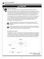
GROUNDING
PIN
SAFETY INFORMATION
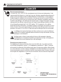
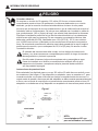
Electrical Connection
Grounding Instructions
A15-Amp,120-Volt,60Hzcircuitwithaproperlygroundedoutletisrequired.
Preferably,thereplacewillbeonadedicatedcircuitasotherappliancesonthe
same circuit may cause the circuit breaker to trip or the fuse to blow when the heater
is in operation. The unit comes standard with a 6 ft. (1.8 m) long three wire cord,
exitingtherightsideofthereplace.Plantheinstallationtoavoidtheuseofan
extension cord. Extension cords are for temporary use only. If an extension cord
mustbeused,itmustbeUL/CSAcertied,ratedat15A(1,875W),125Vmaximum
with14AWGminimumandconstructedoftwocurrentcarryingconductorswith
ground. A heavy duty extension cord with the shortest length possible for the
connection is recommended and must not be longer than 50 ft. (15.2 m).
Do not coil or cover the extension cord.
Electrical outlet wiring must comply with local building codes and other
applicableregulationstoreducetheriskofre,electricalshockandinjury
to persons.
Donotusethisreplaceifanypartofithasbeenunderwater.Immediately
callaqualiedservicetechniciantoinspectthereplaceandreplaceanypart
of the electrical system which has been under water.
This heater is for use on 120 volts. The cord has a plug as shown at (A) in Figure 1.
An adapter as shown at (C) is available for connecting three-blade grounding-type
plugs to two-slot receptacles. The green grounding lug extending from the adapter
must be connected to a permanent ground such as a properly grounded outlet box.
The adapter should not be used if a three-slot grounded receptacle is available.
NOTE: Adapters are NOT
for use in Canada.
DANGER

5
SAFETY INFORMATION
Remote Control
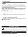
ELECTRICAL, PLUMBING OR GAS LINES MAY BE IN WALL.
Before cutting, drilling or hammering verify their location. If needed, contact your
electrician, plumber or service person.
PRODUCT DAMAGE MAY OCCUR.
Never attempt to disassemble or alter the product in any way not instructed by this manual.
This equipment has been tested and found to comply with the limits for a Class B digital device,
pursuant to Part 15 of the FCC Rules and Industry Canada ICES-003. These limits are designed
to provide reasonable protection against harmful interference in a residential installation. This
equipment generates, uses, and can radiate radio frequency energy and, if not installed and used in
accordance with the instruction manual, might cause harmful interference to radio communications.
However, there is no guarantee that interference will not occur in a particular installation. If this
equipment does cause harmful interference to radio or television reception, which can be determined
by turning the equipment off and on, the user is encouraged to try to correct the interference by one
or more of the following measures:
• Reorientorrelocatethereceivingantenna.
• Increasetheseparationbetweentheequipmentandreceiver.
• Connecttheequipmentintoanoutletonacircuitdifferentfromthattowhichthereceiver
is connected.
• Consultthedealeroranexperiencedradio/TVtechnicianforhelp.
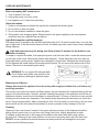
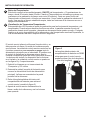
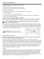
The remote control requires 1 Lithium Coin Cell Battery (size CR2025), which is included.
DO NOT mix old and new batteries.
DO NOT use rechargeable silver oxide cell batteries with remote control unit.
DO NOT mix alkaline, standard (Carbon-Zinc), or rechargeable (Nickel-Cadmium) batteries.
DONOTdisposeofbatteriesinre.Improperdisposalmaycausebatteriestoleakorexplode.
WARNING
CAUTION

6
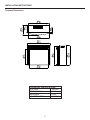
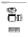
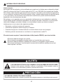
INSTALLATION INSTRUCTIONS
Fireplace Dimensions
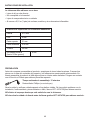
TECHNICAL SPECIFICATIONS
VOLTAGE 120V AC
FREQUENCY 60HZ
MAX AMPS 12.5A
HEATER RATING 1350W

7
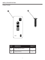
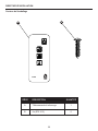
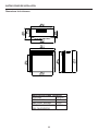
INSTALLATION INSTRUCTIONS
Package Contents
JY-3B
A
B
A 1Infrared Remote Control
PART DESCRIPTION QUANTITY
B 4Screw (ST4 X12)

8
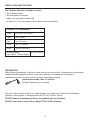
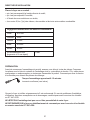
Clearance to Combustibles
Sides 2-27/64 in. (61.5 mm)
Floor 0 in. (0 mm)
Top 2 in. (51 mm)
Front 36 in. (914 mm)
Rear 25/32 in. (20 mm)
Wooden Facing 5/16 in. (8 mm)
[up to 5/8 in. (16 mm) thick]
• Outofdirectsunlight
• Notsusceptibletomoisture
• Awayfromuninsulatedoutsidewall
• Atleast3ft.(.9m)fromdrapery,furnitureandothercombustibles
The Fireplace should be located in an area:
INSTALLATION INSTRUCTIONS
Open the unit and check carefully for visible damage. If you have any problems with installation,
operation, missing parts, or damage,please call 877-447-4768 for service.
DO NOT dispose of packaging until you are satised with your replace.
DO NOT return unit to store before calling 877-447-4768 for service.
PREPARATION
Before beginning assembly of product, make sure all parts are present. Compare parts with package
contents list and hardware contents. If any part is missing or damaged, do not attempt to
assemble the product. Contact customer service for replacement parts.
Estimated Assembly Time: 15 minutes
Phillips Screwdriver (not included)

9
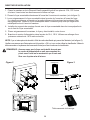
INSTALLATION INSTRUCTIONS
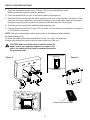
1. Place the assembled mantel near a 15-amp, 120-volt grounded electric outlet.
Read all instructions before using this appliance.
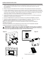
2. Placetheinsertdirectlyinfrontofthemantelopening(Seegure2).
3. Carefullylifttheinsertthroughthecenteropeninginthefrontofthereplace.Thebottomofthe
insert has two foam rubber strips to prevent scratching of the hearth base. Slide the insert back
through the opening until the metal trim makes contact with the front of the mantel.
4. Carefullypositionmantelwithinstalledreplaceagainstwall.
5. Plug the power cord into the 15-amp, 120-volt outlet. Use an extension cord rated for a minimum
of 1,875 watts if necessary.
CAUTION: Make sure that the unit is installed so that the
power cord is not compressed against or caught on the
unit or the mantel and that it has an unobstructed path to
the grounded outlet.
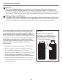
NOTE: This unit comes equipped with a safety switch on the side panel which disables
theheater(Seegure3).
To enable the heater, please ensure the switch is in the “On” mode. The heater will
function using the remote control or control panel on the front of the unit.
Infrared Remote Control
Figure 2 Figure 3
Enable Heater/Calefacción habilitada/
Chauffage activé
Disable Heater/Calefacción deshabilitada/
Chauffage désactivé

10
OPERATING INSTRUCTION
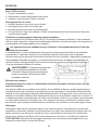
Thereplacefeaturesconvenientlyseparatecontrolsforameeffectandforheatercontrol.
This allows you to operate the unit in two (2) different modes:
• As a full-featured replace-bothameeffectandheaterareon.Thismodeallowsyoutoenjoy
thelookoftherealongwiththeheatoutputofaheater.
• As a visual effect-onlytheameeffectison,theheaterisoff.Werecommendthismodefor
warmweatherapplication,whenyouwanttheambianceofare,withoutanyheatoutput.
Thereplacecontrolfunctionscanbeaccessedintwo(2)ways:
• Usingthetouchpadcontrolpanel,locatedintheupperright-handcornerofthereplace
behind the sliding control panel cover.
• Usingthemultifunctionremotecontrolunit.
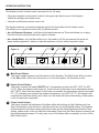
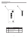
1
2
3
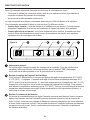
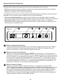
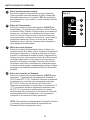
Main Power Button:
Thisbuttonsuppliespowertoallthefunctionsofthereplace.TheMainPowerbuttonmustbe
in the ON position, either from the remote or on the touch pad for the functions to work.
Heater Control Button:
This button controls the heater ON/OFF and 11 temperature modes from 68°F (20°C) to 88°F
(31°C).Whentheheaterisrstturnedon,itwillcomeonatthelowestroomtemperaturesetting
68°F (20°C). Each time the Heater Control button is pressed, the temperature set point increases
2°F(1°C),allowingyoutoadjusttheambienttemperature,upto88°F(31°C).Thereplacewill
remember the last heat setting, and in later use, the heater will start at that setting, unless power
to the unit has been interrupted.
Flame Control button:
ThisbuttoncontrolsthebrightnessoftheameeffectwithsettingsatHigh,MediumandLow.
Whenthereplaceisrstturnedon,theamewillcomeonatthehighestsetting.Thereplace
willrememberthelastamesettingusedandinlaterusetheamebrightnesswillstartatthat
setting, unless power to the unit has been interrupted. Each time the Flame button is pressed, the
amebrightnessdecreases.Theonlywaytoturnofftheameeffectcompletelyistoturnoffthe
Main Power button.
Figure 4
5 4 2 3 1

11
OPERATING INSTRUCTION
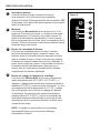
4
5
Timer Button:
This button controls the timer ON/OFF and 10-time setting from 30 minutes to 9 hours. When the
Timerisrstturnedon,itwillcomeonattheshortesttimesetting(30minutes).Eachtimethe
Timer button is pressed, the time increases 1 hour, up to the longest setting (9 hours). Once the
settimeexpires,allreplacefunctionswillbeautomaticallyturnedoff.
Temperature/Timer Display
This LED display shows the set point for the temperature and timer functions. When either of
thesefunctionsisactivated,thedisplayreectsthesetpointforvesecondsandthenfadesto
black. Any change in the set point of the temperature or timer will reactivate the display, which
againfadesafterveseconds.
Theinfraredremotecontrolreliesonalineofsightandmustbepointedattheame/screenofthe
replacetowork.TheremotecontrolunithasthecontrolsrequiredtoturnON/OFF both the main
power and the heater. If you prefer to use the touchpad
controlonthereplaceunititself,thelayout
of the buttons on touchpads and remote control unit can
be seen in Figures 4 and 6, respectively.
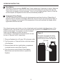
1.Plugyourreplaceintoa15-amp,120-voltpoweroutlet.
2. Turn the power on. Flame will show on the back screen
ofthereplace.
3. Remove plastic tab from inside battery compartment
to activate remote control (See Figure 5).
4.Pointtheremotecontroldirectlyatthereplace
ame/screenandusethebuttonstooperatethe
replace.
The plastic tab inside the battery
compartment MUST be removed
before remote control will operate.
Figure 5
(Pull tab)

12
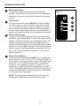
Main Power Button:
This button supplies power to all the functions of the
replace.ThemainpowerbuttonmustbeintheON position,
either from the remote or on the touch pad for the functions
to work.
Timer Button:
This button controls the timer ON/OFF and 10-time setting
from30minutesto9hours.WhentheTimerisrstturned
on, it will come on at the shortest time setting (30 minutes).
Each time the Timer button is pressed, the time increases 1
hour, up to the longest setting (9 hours). Once the set time
expires,allreplacefunctionswillbeautomaticallyturnedoff.
Flame Control button:
Thisbuttoncontrolsthebrightnessoftheameeffectwith
settingsatHigh,MediumandLow.Whenthereplaceisrst
turnedon,theamewillcomeonatthehighestsetting.The
replacewillrememberthelastamesettingusedandin
laterusetheamebrightnesswillstartatthatsetting,unless
power to the unit has been interrupted. Each time the Flame
buttonispressed,theamebrightnessdecreases.Theonly
waytoturnofftheameeffectcompletelyistoturnoffthe
Main Power button.
Heater Control Button:
This button controls the heater ON/OFF and 11 temperature
modes from 68°F (20°C) to 88°F (31°C). When the heater is
rstturnedon,itwillcomeonatthelowestroomtemperature
setting 68°F (20°C). Each time the Heater Control button
is pressed, the temperature set point increases 2°F (1°C),
allowing you to adjust the ambient temperature, up to 88°F
(31°C).Thereplacewillrememberthelastheatsetting,and
in later use, the heater will start at that setting, unless power
to the unit has been interrupted.
NOTE: To switch between Fahrenheit/Celsius modes see
control panel Fahrenheit/Celsius display instructions.
OPERATING INSTRUCTION
1
2
3
4
Figure 6
2
3
4
1

13
CARE AND MAINTENANCE
Glass Information:
Maintenance of Motors:
Before attempting ANY maintenance:
1. Turn off power to the unit.
2. Unplug the power cord from outlet.
3. Letreplacecoolifithasbeenoperating.
1. Under no circumstances should this product be operated with broken glass.
2. Do not strike or slam the glass.
3. Do not use abrasive cleaners to clean the glass.
4. This product uses tempered glass. Replacement of the glass supplied by the manufacturer
shouldbedonebyaqualiedserviceperson.
Always disconnect the appliance from the main power supply and allow it to cool before any
servicing operation.
Themotorsusedonthefanheaterandameblowerarepre-lubricatedforextendedbearinglifeand
require no further lubrication. However, periodic cleaning/vacuuming of the appliance around the air
intake and exhaust, as well as the fan heater is recommended. For heavy or continuous use, periodic
cleaning must be done more frequently. If the heater blows alternating cold and warm air, check the
fanforfreemovementandfordebrisrestrictingairow.Ifthefandoesnotmovefreely,theunitmust
be turned off and the fan replaced immediately in order to prevent further damage to the unit.
Cleaning:
Cleaningofthecontrolpanel,locatedintheupperright-handcornerofthereplacebehindthe
sliding control panel cover, is to be done only using a soft cloth, slightly dampened in water
(if needed, a small amount of dish soap can be added to the water) and dried using a clean,
dry soft cloth. Cleaning of the screen diffuser is to be done using only water and a lint free cloth.
DO NOT use any abrasive household cleaners as these products will damage the touch-pad
controls and the diffusing screen.
Light Bulb Inspection and Replacement
The ame effect is created by two 40-Watt light bulbs with an E-12 (small) socket base. Use only this
type of light bulb. If the ame effect does not work, the bulbs may have come loose or been damaged
during shipping.
To inspect or replace the bulbs, rst unplug the power cord from the outlet. Locate the access panel
on the back of the stove. Remove the screws and the panel. Check the bulbs to be sure they are
nger tight and in working order. Replace any damaged or faulty bulbs. Reattach the access panel.
Do not operate this heater without the access panel in place. Do not remove the back cover of this
heater. There are no serviceable parts inside.
Light bulbs become very hot during use. Allow at least 10 minutes for the bulbs to cool
before touching.
WARNING: Do not exceed 40 watts per bulb.
Use of higher rated bulbs may result in a re,
causing property damage or personal injury.

14
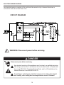
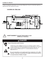
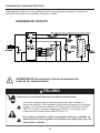
Disconnect power before servicing.
Anyelectricalre-wiringofthisappliancemustbedonebyaqualiedelectrician.
This wiring must be done in accordance with local codes and/or in Canada with
the current CSA C22.1 Canadian Electrical Code, and for US installations, the
National Electrical Code ANSI/NFPA NO 70.
If repairing or replacing any electrical component or wiring, the original
wire routing, color coding and securing locations must be followed.
DANGER
Any electrical repairs or rewiring of this unit should be carried out by a licensed electrician in
accordance with national and local codes.
ELECTRIC WIRING DIAGRAM
CIRCUIT DIAGRAM
WARNING: Disconnect power before servicing.

15
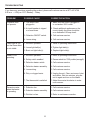
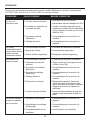
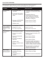
TROUBLESHOOTING
If you have any questions regarding the product, please call customer service at 877-447-4768
8:30 a.m. – 4:30 p.m. CST, Monday – Friday.
PROBLEM POSSIBLE CAUSE CORRECTIVE ACTION
Fireplace does
not operate.
Power light is ON
but the ame effect
is not visible.
Excessive noise
when the heater
is operating.
Heater is not
operating.
1. The stove is not
plugged in.
2. A circuit breaker is tripped
or a fuse blown.
3. Defective ON/OFF switch.
4. Loose wiring.
1. Incorrect operation.
2. Loose light bulb(s).
3. Burnt out light bulb(s).
1. Defective fan.
2. Defective heater assembly.
3. Dirt/dust on fan.
1. Incorrect operation.
2. Safety switch enabled
3. Defective heater switch.
4. Defective heater assembly.
5. Loose wiring.
6. Dirty or clogged vents.
7. The thermostat is satised.
1. Make sure the stove is plugged in
to a standard 120V outlet.
2. Check additional appliances on the
circuit; ideally the stove should be
on a dedicated 15 Amp circuit.
3. Call customer service.
4. Call customer service.
1. Refer to operating instructions.
2. Tighten light bulb(s).
3. Replace light bulb(s).
1. Call customer service.
2. Call customer service.
3. Refer to maintenance section.
1. Refer to operating instructions.
2. Ensure switch is in "ON" position (see pg 8)
3. Call customer service.
4. Call customer service.
5. Call customer service.
6. Unplug the unit. Clear vent area of dust
and debris. Wait ten minutes, plug the
unit in again and turn on the heater.
7. Adjust thermostat clockwise to make
room warmer.

16
Themanufacturerwarrantsthatyournewelectricreplaceisfreefrommanufacturingand
material defects for a period of one year from date of purchase, subject to the following conditions
and limitations.
1. Thiselectricreplacemustbeinstalledandoperatedatalltimesinaccordancewiththe
instructions furnished with the product. Any alteration, willful abuse, accident, or misuse of the
product shall nullify this warranty.
2. This warranty is non-transferrable, and is made to the original owner, provided that the purchase
wasmadethroughanauthorizedsupplierofthemanufacturer.
3. This warranty is limited to the repair or replacement of part(s) found to be defective in material
or workmanship, provided that such part(s) have been subjected to normal conditions of use and
service,aftersaiddefectisconrmedbythemanufacturer’sinspection.
4. The manufacturer may, at its discretion, fully discharge all obligations with respect to this warranty
by refunding the wholesale price of the defective part(s).
5. Any installation, labor, construction, transportation, or other related costs/expenses arising from
defective part(s), repair, replacement, or otherwise of same, will not be covered by this warranty,
nor shall the manufacturer assume responsibility for same. Further, the manufacturer will not be
responsible for any incidental, indirect, or consequential damages, except as provided by law.
6. All other warranties - expressed or implied - with respect to the product, its components and
accessories, or any obligations/liabilities on the part of the manufacturer are hereby expressly
excluded.
7. Themanufacturerneitherassumes,norauthorizesanythirdpartytoassume,onitsbehalf,
any other liabilities with respect to the sale of this product.
8. The warranties as outlined within this document do not apply to non-manufacturer accessories
used in conjunction with the installation of this product.
This warranty is void if:
a) Thereplacehasbeenoperatedinatmospherescontaminatedbychlorine,uorineorother
damaging chemicals.
b)Thereplaceissubjectedtoprolongedperiodsofdampnessorcondensation.
c) Any alteration, willful abuse, accident, or misuse of the product.
IF WARRANTY SERVICE IS NEEDED . . .
1) Contact customer service. Make sure you have your warranty, your sales receipt, and the
model/serial number of your product.
2)DONOTATTEMPTTODOANYSERVICEWORKYOURSELF.
WARRANTY
GHP Group, Inc.
6440 W. Howard St.
Niles, IL 60714-3302
877-447-4768

17
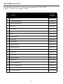
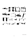
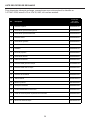
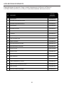
REPLACEMENT PARTS LIST
For replacement parts, call our customer service department at 877-447-4768,
8:30 a.m. – 4:30 p.m. CST, Monday – Friday.
Ref.
24-900-001,
GLF-2404,
GEF24CRG11
1 EF24900001AC
2 EF24900002AC
3 EF24900003AC
4 EF24900004AC
5 EF24900005AC
6 EF24900006AC
7 EF24900007AC
8 EF24900008AC
9 EF24900009AC
10 EF24900010AC
11 EF24900011AC
12 EF24900012AC
13 EFEST330008ST
14 EF24900013AC
15 EF33510AS-12
16 EFES323020ST
17 EF24900014AC
18 EF24900015AC
19 EF24900016AC
20 EF24900017AC
21 EFES323021ST
Curve logset
Left side panel assembly
Control panel circuit board
Synchronous motor
Control panel
Remote control
Toggle switch
Power cord & connector
Description
Top panel
Trim assembly
Flame panel
Heater
Projection screen
Right side panel assembly
Back panel
Main board
Lamp socket & bracket
Flame reflector
Left brick side panel
Right brick side panel
Access panel

18
Printed in China

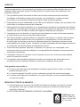
19
Des questions, des problèmes, des pièces manquantes? Avant de retourner
l’articleaudétaillant,appeleznotreserviceàlaclientèleau8774474768,
entre8h30et16h30,HNC,dulundiauvendredi,ouenvoyez-nousuncourrielà
l’adressesuivante:[email protected].
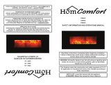
DIRECTIVES D’INSTALLATION ET D’UTILISATION
À installer avec le
manteau pour foyer
Pleasant Hearth.
C US
REMARQUE À L’INTENTION DE L’INSTALLATEUR : Veuillez laisser ce manuel au propriétaire.
REMARQUE À L’INTENTION DU CLIENT : Veuillez conserver ce manuel pour vous
y référer ultérieurement.
AVERTISSEMENT!
RESPECTEZ SCRUPULEUSEMENT LES DIRECTIVES DU PRÉSENT MANUEL
POUR PRÉVENIR LES CHOCS ÉLECTRIQUES, LES INCENDIES, LES
DOMMAGES AINSI QUE LES BLESSURES GRAVES OU MORTELLES.
CONSIGNES IMPORTANTES
VEUILLEZ LIRE CE MANUEL AVANT D’INSTALLER OU D’UTILISER LE FOYER.
FOYER ÉLECTRIQUE ENCASTRABLE PLEASANT HEARTH
MODÈLE Nº #24-900-001, GLF-2404, GEF24CRG11
FRANCÁIS
20-10-175 Rev. 7/13
6440 W. Howard St.
Niles, IL 60714-3302
877-447-4768

20
IMPORTANT : Lisez attentivement toutes les directives et les avertissements avant
de procéder à l’installation. Le non-respect de ces directives peut provoquer un choc
électrique, des blessures et un incendie, et annule la garantie.
Veuillez lire les directives d’installation et d’utilisation avant d’utiliser ce foyer.
TABLE DE MATIÉRES
Consignesdesécurité .................................................................................................................... 21
Directivesd’installation ................................................................................................................... 25
Directivesd’utilisation ..................................................................................................................... 29
Entretien .........................................................................................................................................32
Schémadecâblage ........................................................................................................................33
Dépannage .....................................................................................................................................34
Garantie ..........................................................................................................................................36
Liste des pièces de rechange ......................................................................................................... 37
Merci et félicitations pour votre achat d’un foyer
électrique de GHP Group.
La page est en cours de chargement...
La page est en cours de chargement...
La page est en cours de chargement...
La page est en cours de chargement...
La page est en cours de chargement...
La page est en cours de chargement...
La page est en cours de chargement...
La page est en cours de chargement...
La page est en cours de chargement...
La page est en cours de chargement...
La page est en cours de chargement...
La page est en cours de chargement...
La page est en cours de chargement...
La page est en cours de chargement...
La page est en cours de chargement...
La page est en cours de chargement...
La page est en cours de chargement...
La page est en cours de chargement...
La page est en cours de chargement...
La page est en cours de chargement...
La page est en cours de chargement...
La page est en cours de chargement...
La page est en cours de chargement...
La page est en cours de chargement...
La page est en cours de chargement...
La page est en cours de chargement...
La page est en cours de chargement...
La page est en cours de chargement...
La page est en cours de chargement...
La page est en cours de chargement...
La page est en cours de chargement...
La page est en cours de chargement...
La page est en cours de chargement...
La page est en cours de chargement...
La page est en cours de chargement...
La page est en cours de chargement...
-
 1
1
-
 2
2
-
 3
3
-
 4
4
-
 5
5
-
 6
6
-
 7
7
-
 8
8
-
 9
9
-
 10
10
-
 11
11
-
 12
12
-
 13
13
-
 14
14
-
 15
15
-
 16
16
-
 17
17
-
 18
18
-
 19
19
-
 20
20
-
 21
21
-
 22
22
-
 23
23
-
 24
24
-
 25
25
-
 26
26
-
 27
27
-
 28
28
-
 29
29
-
 30
30
-
 31
31
-
 32
32
-
 33
33
-
 34
34
-
 35
35
-
 36
36
-
 37
37
-
 38
38
-
 39
39
-
 40
40
-
 41
41
-
 42
42
-
 43
43
-
 44
44
-
 45
45
-
 46
46
-
 47
47
-
 48
48
-
 49
49
-
 50
50
-
 51
51
-
 52
52
-
 53
53
-
 54
54
-
 55
55
-
 56
56


Pleasant Hearth 24-900-001 Homeowner's Installation And Operating Instructions Manual
- Catégorie
- Chauffe-eau
- Taper
- Homeowner's Installation And Operating Instructions Manual
- Ce manuel convient également à
dans d''autres langues
- English: Pleasant Hearth 24-900-001
- español: Pleasant Hearth 24-900-001
Documents connexes
-
Pleasant Hearth SES-42 Important Instructions Manual
-
-
-
-
-
-
-
-
-
Autres documents
-
Muskoka MFB25WSC-1 Mode d'emploi
-
-
Heat & Glo E-Stove Install Manual
-
 FLAMELUX Z1520026R Mode d'emploi
-
World Marketing of America Keystone Mode d'emploi
-
Ameriwood HD93815 Guide d'installation
-
 American Comfort SILVER ACW0032 Manuel utilisateur
-
Duraflame DFI-550-22 Black Infrared Freestanding Electric Fireplace Stove Manuel utilisateur
-
Legrand Single to Triple Outlet Adaptor, 1219 Guide d'installation
-
 HomComfort EWH58 Mode d'emploi


