
|| Krentz Photography, Germany
Scoro
Operating instructions | Bedienungsanleitung | Mode d‘emploi
Bron Elektronik AG
4123 Allschwil 1 / Switzerland
www.broncolor.swiss
|| Reinhard Scheuregger, Germany
BA114.00 | Printed in Italy 03/22
|| Nadja Winzenried, Switzerland
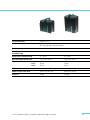
Scoro S WiFi / RFS 2
Scoro E WiFi / RFS 2

5
13
14
15
16
12 11 10 9.2
9.1
7.2
7.1
8
6.1
6.2
20 22 1 2 3 423 21
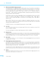
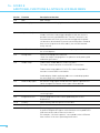
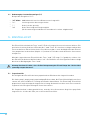
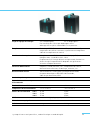
Eléments de commande et d‘affichage
1. Interrupteur principal
2. Disjoncteur
3. Prise de raccordement pour ordinateur
4. Prise de synchronisation
5. Prise pour raccordement câble réseau
6.1 Prise de torche 1
6.2 Prise de torche 2
6.3 Prise de torche 3*
7.1 Interrupteur torche 1, en / hors service
7.2 Interrupteur torche 2, en / hors service
7.3 Interrupteur torche 3, en / hors service*
8. Cellule réceptrice IR et cellule photo-électrique*
9.1 Réglage de la puissance torche 1 "q/p"
9.2 Réglage de la puissance torche 2 "q/p"
9.3 Réglage de la puissance torche 3 "q/p"*
10. Réglage principal de la puissance "q/p"
11. Affichage numérique de la répartition lumineuse par torche
12. Affichage numérique principal de la puissance
13. Cellule photo-électrique marche / arrêt
14. Cellule réceptrice IR et / ou interface RFS marche / arrêt
15. Lumière de mise au point marche / arrêt
16. Touche "test", indicateur de disponibilité bleu, indicateur de défaillance rouge
17. Touche "speed" (pour temps de charge et durée d’éclair courts)*
18. Touche "user" (touche utilisateur)*
19. Touche "reset" (touche de réinitialisation)*
20. Affichage LCD
21. Touche de sélection (fonction d’affichage identique à l’affichage LCD)
22. Touche "menu"
23. Poignée avec antenne intégrée
* seulement Scoro S
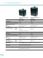
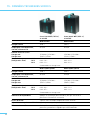
Scoro E
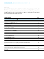
SCORO BESTSELLER
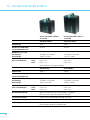
Pulso G
1600 J: 120 V 32.115.XX | 230 V 32.098.XX
3200 J: 120 V 32.116.XX | 230 V 32.099.XX
Reflector "Beauty Dish"
Reflektor "Beauty Dish"
Réflecteur "Beauty Dish"
33.111.00
Picobox for Picolite
Picobox zu Picolite
Picobox pour Picolite
33.128.00
Attachment with 3 honeycomb grids and 2 aperture masks
Vorsatz mit 3 Wabenrastern und 2 Lochmasken
Adaptateur avec 3 nids d‘abeilles et 2 masques à trou
for / zu / pour Picolite / Mobilite 2
33.204.00
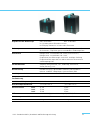
Pulso Adapter for Picolite / Mobilite 2
Pulso Adapter zu Picolite / Mobilite 2
Adaptateur Pulso pour Picolite / Mobilite 2
33.501.00
Fresnel spot attachment for Picolite / Mobilite 2
Fresnel-Spotvorsatz zu Picolite / Mobilite 2
Adaptateur spot Fresnel pour Picolite / Mobilite 2
33.631.00
Projection attachment for Picolite
Projektionsvorsatz zu Picolite
Adaptateur de projection pour Picolite
33.641.00
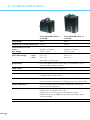
Picolite
32.021.00
Boxlite 40
32.341.XX (5500 K)
Litestick
32.451.00 (5500 K*)
Ringflash C
32.462.XX
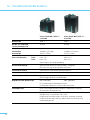
Balloon
33.161.00
Honeycomb grids for Ringflash C, 3 pieces
Wabenraster zu Ringflash C, 3 Stück
Grilles en nid d‘abeilles pour Ringflash C
33.219.00
Para 88 Kit without adapter
Para 88 Kit ohne Adapter
Para 88 Kit sans adaptateur
33.483.03
Para 88 reflector
Para 88 Reflektor
Réflecteur Para 88
33.482.00
*guarantees neutral colour reproduction, garantiert eine neutrale Farbwiedergabe, assure une reproduction neutre des couleurs
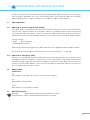
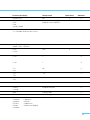
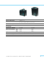
Bedienungs- und Anzeigeelemente
1. Netzschalter
2. Sicherungsautomat
3. Computeranschlussbuchse
4. Synchronbuchsen
5. Anschlussdose für Netzkabel
6.1 Leuchtenbuchse 1
6.2 Leuchtenbuchse 2
6.3 Leuchtenbuchse 3*
7.1 Leuchtenanschluss 1, ein / aus
7.2 Leuchtenanschluss 2, ein / aus
7.3 Leuchtenanschluss 3, ein / aus*
8. IR Empfängerzelle und Fotozelle*
9.1 Energieregelung Leuchte 1 "q/p"
9.2 Energieregelung Leuchte 2 "q/p"
9.3 Energieregelung Leuchte 3 "q/p"*
10. Hauptenergieregelung "q/p"
11. Leuchtzifferanzeige für Blitzenergieverteilung
pro Leuchte
12. Leuchtziffer Hauptenergieanzeige
13. Fotozelle ein / aus
14. IR-Empfänger und / oder RFS-Interface ein / aus
15. Einstelllicht ein / aus
16. Test-Taste & Bereitschaftsanzeige blau,
Störungsanzeige rot
17. Speed-Taste (für schnelle Lade- und Blitzabbrennzeiten)*
18. User-Taste (Benutzer Taste)*
19. Reset-Taste (Rücksetz Taste)*
20. LCD-Display
21. Auswahl-Tasten (Funktion analog Anzeige im LCD-Display)
22. Menu-Taste
23. Griff mit eingebauter Antenne
* nur Scoro S
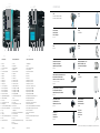
Controls and displays
1. Mains switch
2. Circuit breaker
3. Connection socket for computer
4. Sync socket
5. Connection socket for mains cable
6.1 Lamp outlet 1
6.2 Lamp outlet 2
6.3 Lamp outlet 3*
7.1 Lamp key 1, on / off
7.2 Lamp key 2, on / off
7.3 Lamp key 3, on / off*
8. IR receiver cell and photocell*
9.1 Power selector lamp 1 "q/p"
9.2 Power selector lamp 2 "q/p"
9.3 Power selector lamp 3 "q/p"*
10. Master power selector "q/p"
11. Digital power distribution display per lamp
12. Digital master power display
13. Photocell on / off
14. IR receiver and / or RFS-interface on / off
15. Modelling light on / off
16. Test key and "ready" indicator blue, fault display red
17. Speed key (for fast charge and flash duration)*
18. User key*
19. Reset key*
20. LCD display
21. Selection keys (function analogue to display in LCD)
22. Menu key
23. Handle with integrated antenna
* Scoro S only
5
13
14
15
16
17
18
19
12 11 10 9.3
9.2
9.1
7.3
7.2
7.1
8
6.1
6.2
6.3
20 22 1 2 3 423 21
Scoro S


OPERATING INSTRUCTIONS | BRONCOLOR SCORO S | E
Before use
We are pleased you have chosen a broncolor Scoro power pack which is a high-quality product in every
respect. If used properly, it will render you many years of good service. Please read all the information
contained in these operating instructions carefully. They contain important details on the use, safety
and maintenance of the appliance. Keep these operating instructions in a safe place and pass them on
to further users if necessary.
Observe the safety instructions.
Contents Page
Important safety instructions 6
1. Start up 9
2. LCD display and menu system 10
3. Energy control 12
4. Lamp outlets 13
5. Modelling light 14
6. Release 16
7. bronControl App and WiFi settings 17
8. Displays visual / audible 18
9. Special functions 19
10. Protective facilities 21
11. Lamp compatibility 21
12. Service / repair 21
13. Additional functions and their listing in LCD main menu Scoro S 22
14. Additional functions and their listing in LCD main menu Scoro E 28
15. Technical data Scoro S WiFi / RFS 2 30
16. Technical data Scoro E WiFi / RFS 2 32
17. Environmental protection information 34
18. Guarantee 34

6
IMPORTANT SAFETY INSTRUCTIONS
broncolor flash light systems should be utilised exclusively for professional photo shootings by
qualified personnel. Before starting up your flash light equipment carefully read all the informa-
tion in your operating instructions. The safety instructions in the operating instructions must be
strictly followed!
> Read and understand all instructions before using!
> Remove the transport protection and the packing material!
> Close supervision is necessary when any appliance is used near children. Do not leave the flash
light appliance unattended while in use!
> Flash light contains, similar to sunlight, a specific portion of UV radiation! The undesirable side ef-
fects on skin and eyes are considerably reduced by using flash tubes or protecting glasses with UV
safety measures! Nevertheless, taking pictures at close distances with unprotected skin and eyes
should be avoided! Also avoid eye contact with the light source! The maximum daily UV radiation
according to IEC 60335-2-27 / DIN 5031-10 is: 50 J/m2. This value should not be exceeded!
> With due allowance for heat radiation, the distance between the lamp and a person or between the
lamp and inflammable or heat sensitive surfaces should be at a minimum distance of 1 m!
> The power pack must be switched off to plug-in and to unplug! The lamp plugs and sockets have
mechanical interlocks! When plugging in, ensure that those interlocks engage completely! To
unplug, push down the locking spring below the cable guide and lift out the plug from the socket!
> Prior to replacing flash tubes, halogen lamps, protecting glasses or fuses, disconnect the power
pack and the lamp from the power supply! Prior to replacing the halogen lamp or the flash tube,
the lamp should cool down for 10 min.!
> broncolor flash light systems should only be equipped with original broncolor flash tubes, original
broncolor combustible and packing material, original broncolor accessories, and also original
broncolor spare parts!
> broncolor power packs, lamps and accessories meet an extremely high safety standard! When
connecting broncolor lamps to power packs of other brands or broncolor power packs to lamp
bases or accessories of other brands, integrated safety measures may become ineffective! Due
to different design features and contact assignment of the lamp plugs of other brands, the user
himself / herself may even be at risk. We offer no guarantee and accept no liability for damages
which may be caused by this type of usage!
> Only lamps which are approved for operation with this power pack should be utilised!
> Only earthed extension cables which are approved for operation with the corresponding lamp
should be utilised!
> To avoid the risk of fire, electric shock or injury to persons utilise exclusively the accessory recom-
mended by the manufacturer!
> Check that the mains voltage corresponds to the information on the type plate of the unit!
> The flash light equipment is designed for use in dry conditions and in an ambient temperature
from 0 °C to 35 °C! The flash light equipment has to be protected from wetness, condensation,
from dripping and splash water, humidity, dirt, sand, metal chips and exposure to dust!

7
> Protect the flash light equipment from electromagnetic fields, shock and vibration!
> Protect the flash light equipment from heat and frost! If the power pack freezes continuous
loss of power output and serious technical damage can result!
> Sudden temperature differences can cause condensation water in the unit! In such situations
the equipment must stay for 1 hour in a well ventilated place to acclimatise to the new tem-
perature before start up!
> Do not operate the units in an environment where there is a risk of explosion!
> The power pack should not be operated in or near water! Attention: high voltage!
> The power pack and the lamps should not be immersed in water or other liquids!
It could cause an electric shock!
> Remove the transport protection cap on the front side of the lamp before connecting it to the
power pack!
> For safety reasons, never operate the lamp base without the protecting glass in place! UV-
coated protecting glasses or UV-coated flash tubes must be utilised as a protection against UV
radiation for eyes and skin!
> Before operation the lamp has to be fastened on a stand or a suspension device!
The lamp must be locked by tightening the mounting screw!
> Only sand-filled fuses of the type indicated on the safety type plate may be used! Sand-filled
fuses can be identified by their opaque fuse body! With incorrect fuse protection the halogen
lamp may burst!
> Filters or diffusers should not be fastened directly on the flash tube, halogen modelling lamp
or protecting glass!
> Do not operate appliance with a damaged earthed cable. Cables which are damaged or twisted
must be replaced!
> The unit must only be connected to an earthed socket, or an emergency power generator!
> If an extension cable is necessary, a cable with a current rating at least equal to that of the
appliance should be used. Cables rated for less amperage than the appliance may overheat.
When using a cable reel, it must be completely unrolled before use to prevent overheating of
the cable!
> The unit is suitable for operation with a motor generator provided that the voltage lies within
all the load conditions (including capacitive load) and within the tolerance limit of 200 – 264 V
or 95 – 135 V! From experience this means that only electronic stabilised motor generators are
to be utilised! When operating on unstabilised motor generators, voltage peaks of 300 V and
more have been observed! This can lead to damages for which we assume no liability!
> Do not operate the lamps inside a bag or a box!
> The ventilation slots on the unit or on the lamp should not be covered!
> Pay attention when laying, clearing away or rolling up cables that they do not contact hot sur-
faces or parts of lamps and that they will not be tripped over by persons!

8
> Do not touch the connection socket for mains cable and lamp outlets on the power pack and do not
poke in them with metal objects!
> Flash tubes, halogen modelling lamps and protecting glasses heat up to a high operating tem-
perature, this also applies to the front side of the lamps! Therefore the attachments also assume
high temperatures! Handle with care! Contact with hot components can cause injuries!
> Do not come into contact with glass or metal whilst operating the flash light system!
> Let the unit and its connected lamp base cool completely after use and before packing!
> Always unplug appliance from electrical socket before cleaning and servicing and when not in use!
Never jerk cable to pull the plug from the socket. Grasp plug and pull to disconnect!
> Dropped or damaged units or lamps must be checked by a specialist before reconnection!
>
To reduce the risk of electric shock, never open the power pack or lamps! Dangerous voltages
could still remain inside the unit even after it has been disconnected from the mains supply. There-
fore, take the unit to an authorised broncolor service station when service or repair work is required.
Incorrect reassembly can cause electric shock, even when the unit is closed.
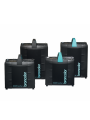
Shipping instructions Scoro:
> Use original broncolor packing for the transport of the power pack!
Shipping instructions lamps:
> Use original broncolor packing for the transport of the lamps. Before shipping flash tubes, halo-
gen lamp and protecting glass pack them with our protective packing material (foam plastic and
transport cap). If the protective packaging is incomplete, remove flash tube, halogen lamp and
protecting glass from the lamp and send them separately!
IMPORTANT SAFETY INSTRUCTIONS

9
We thank you very much that you have chosen a "Scoro" power pack which is a high-quality pro-
duct in every respect. If used properly, it will render you many years of good service.
Please read all the information contained in these operating instructions carefully and keep the
manual in a safe place for all users to retrieve the best from the power packs.
1. START UP
1.1 Mains voltage
As a standard feature, all the Scoro power packs are supplied as multi-voltage units.
The Scoro power packs automatically adapt to the respective mains voltage.
Scoro power packs deliver for all operating voltages (85 – 240 V) constant 1600 J or 3200 J.
Attention: Ensure that the operating voltage of the modelling lamp corresponds to the local
mains supply (max. 650 W on 200 – 240 V or 300 W on 100 – 120 V).
Please note: Since November 2019 broncolor is supplying 300 W modelling lamps only.
1.2 Earthed mains (AC-line)
Always connect unit to current supply always using an earthed mains plug.
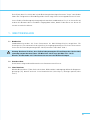
1.3 Start up
Use the mains (AC-line) switch (1) to power up the unit. During the charging process, the digital
master power display (12) flashes, after which, it becomes continuous (see section 8, "Displays
visual / audible").

10
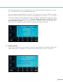
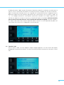
2. LCD DISPLAY AND MENU SYSTEM
It has never been so easy to activate that many settings with so few keys; thanks to the LCD
display. The display is a significant tool, and therefore it is important that, firstly, you become well
acquainted with the structure of the menu system.
The brightness of the user interface can be automatically or manually* dimmed dependent on the
ambient light. See LCD setting function "Brightness display" (section 13.19).
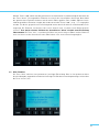
2.1 LCD display menu system
Directly after switching on the unit a start display appears for approximately 5 s with information
about the unit and the owner. Afterwards the unit changes automatically to the normal operat-
ing mode. By default, the flash duration (t 0.1) is shown permanently. In addition, depending on
whether the flash duration or the colour temperature have been altered*, the display will adjust
and the current value will be indicated.
Scoro E shows additionally the performance in joules of the connected lampheads.
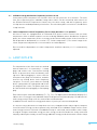
When delay (dly), sequence (seq), interval (int), alternate (alt) are activated as well as the studio
and unit address (if desired), the corresponding functions will be shown on the main page. The
functions shown in the display give an overview of the most important activated additional func-
tions of the power pack*.
The main menu is called up with the key "menu" (22). At the same time, at the bottom edge of the
display, a user guide appears, showing the selection keys (21 & 22) each with their supplementary
functions ("q/p", "+/–", "select", "cancel", "quit", "help"). To return to normal mode, press the key
"menu" (22). Each set value is displayed in a box at the top of the LCD.
* Scoro S only

11
The desired unit functions are selected with the keys "q/p" and confirmed with the key "select".
The selected function is visually highlighted with a bar.
After selecting the desired function, one reaches the second level. There, the options are visible
within the chosen function, which can then be selected with the keys "q/p", or "–/+". The previ-
ously stored setting is always indicated in a box at the top line. The function on which the cursor
is currently positioned is marked with a bar. The new setting will only be set after the "select"
key has been pressed again. The key "quit" or menu (22) leads back to the respective higher level.
Therefore, it is also possible to quit the submenu without storing a new setting.
2.2 Auxiliary function
The key "help" activates an info text for the respective setting. A practical short description of the
addressed functions is stored there. To return to the main menu press the key "menu" (22).

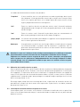
12
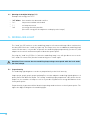
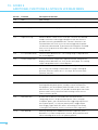
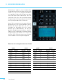
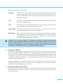
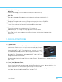
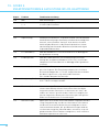
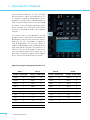
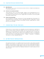
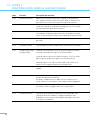
3. ENERGY CONTROL
Use the "q/p" keys (9.1,9.2,9.3*) to control the
flash energy (flash intensity) on each individual
outlet (1, 2 & 3*) within the respective range of
f-stops. The entire energy, however, cannot ex-
ceed 1600 J respectively 3200 J. A value of 10 in
the digital master power display (12) indicates
maximum intensity, 1.0 respectively 0.1 mini-
mum intensity (3 joules).
Whole numbers are full f-stops, decimals indi-
cate 1/10 of a whole f-stop. Brief pressure on
the keys "q/p" (9.1, 9.2, 9.3*, 10) runs the power
up (or down) by a 1/10 f-stop level, prolonged
pressure by a full f-stop. The digital display (12)
then blinks until charging or discharging has
reached the newly selected level and the "test"
key light (16) goes out. An acoustic signal an-
nounces that the new energy level has been
achieved.
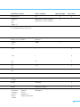
3200 E 1600 E
Energy f-stop Energy f-stop
3200 J 10 1600 J 10
1600 J 9800 J 9
800 J 8400 J 8
400 J 7200 J 7
200 J 6100 J 6
100 J 550 J 5
50 J 425 J 4
25 J 312 J 3
12 J 2
3200 S 1600 S
Energy f-stop Energy f-stop
3200 J 10 1600 J 10
1600 J 9800 J 9
800 J 8400 J 8
400 J 7200 J 7
200 J 6100 J 6
100 J 550 J 5
50 J 425 J 4
25 J 312 J 3
12 J 26 J 2
6 J 13 J 1
3 J 0.1
Overview power range of Scoro E and S
* Scoro S only

13
3.1 Individual energy distribution (asymmetry) & flash cut-off
Scoro power packs incorporate an electronic flash cut-off system for all 3 channels. The units
have two respectively three individual lamp outlets which can be controlled, with neutral col-
our (Enhanced Colour Temperature Control) over the whole range, and with asymmetry up to
6 f-stop intervals and independently of each other. The unit allows power selection in 1/10 and whole
f-stop intervals.
3.2 Colour temperature control / Asymmetry (in case flash duration t 0.1 is optimal)*
All Scoro S units are equipped with an enhanced ECTC process which ensures that no colour
temperature shifts or double exposure can occur during individual power distribution. On partial
power, the colour temperature of the set energy can be influenced by relative shifts in intervals of
200 K upwards or downwards (see section 13.5, "Colour temperature"). The control range of the
colour temperature adjustment is increased when on reduced power.
Due to the direct dependence of colour temperature and flash duration, t 0.1 is automatically
adjusted.
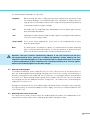
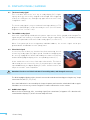
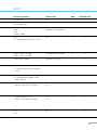
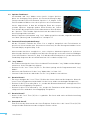
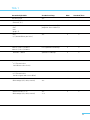
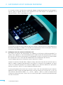
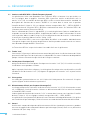
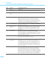
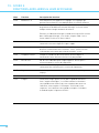
4. LAMP OUTLETS
The lamp outlets of the Scoro units are marked
with the numerals 1 – 2 respectively 1 – 3. Lamp
plugs and sockets have a mechanical locking
device to prevent them from accidentally com-
ing loose. When plugging in, ensure that the
front part of the plug is inserted first, and after
that the rear locking device locks completely
into place. To release, press down the locking
device spring under the cable guide and lift out
the plug from the socket. The power pack must
be switched off whilst plugging in and unplug-
ging.
Each outlet may be switched individually (7.1, 7.2, 7.3*). The digital power distribution displays (11)
indicate the set energy of each individual lamp. The digital master power display (12) indicates the
total energy control range of all the connected or activated lamps.
In addition Scoro E shows the energy performance in joules per connected lamphead.
It is unnecessary to disconnect a lamp when not in use, simply deactivate it by using the lamp out-
let on/off switch. Energy can be asymmetrically allocated to the individual lamps until the maxi-
mum energy has been achieved. If an additional lamp is connected, and should the other lamps
already be using the maximum energy, no more energy can be allocated to the newly connected
lamp. By reducing the already set total energy, additional energy can be allocated to a further lamp.
* Scoro S only

14
4.1 Meaning of the digital displays (11)
Example with energy level "8.7":
> "8.7" blinks flash monitor has detected a misfire
> "—" lamp connected but switched off
> " " no lamp connected
> "-o" no energy allocation possible
(the entire energy has already been used up by other lamps)
5. MODELLING LIGHT
The "mod" key (15) switches on the modelling lamp for all connected lamps. When switched on,
the blue LED next to the "mod" key lights up. The lamps have also an additional modelling lamp
switch. Furthermore, it is possible to operate the modelling light proportionally (section 6.1) and
adapt it to the various maximum outputs of broncolor power packs.
Pressing the "mod" key (15) (for 1 s) when the modelling lamp is on, will give direct access to the
"full" mode. To return to the previous mode briefly press "mod" again.
Attention: Please ensure that the modelling lamp voltage corresponds with the local mains
(AC-line) voltage.
5.1 Proportionality
The modelling light brightness can be set proportionally to the flash intensity.
Stages prop1, prop2, prop3, prop4 and prop5 are used to adapt the modelling light brightness of
power packs with different output. The setting "modelling light proportional" duly allows for the
output set, the number of lamps as well as a possible asymmetrical energy distribution of the
Scoro power packs.
Proportionality is guaranteed if the identical operating mode has been set for all power packs. The
higher the digit, the brighter the modelling light.

15
The following operating modes are possible:
"propmax" When working with only a single power pack (in asymmetrical operation); using
the setting "propmax", the modelling light of the lamp with the highest flash en-
ergy operates at full output, and the other lamps will be proportionally dimmed,
in accordance with their power settings.
"full" All lamps with full modelling light, independent of flash output, type of power
pack and output distribution.
"low" Lighting level reduced for all lamps to reduce power consumption and extend the
service life of the halogen lamps.
"prop1-prop5" These levels allow adapting the Scoro units to the proportionality of other
broncolor power packs.
Note: If a power pack is used with less power, it is known that the halogen modelling
light is relatively weak and yellowish. To solve this problem, all broncolor power
packs may be operated with higher modelling light proportionality.
Attention: The Scoro software automatically indicates in the LCD selection text the pos-
sible proportionality levels, and warns of sudden altered power settings made by the user.
Important: The modelling lights of all the connected lamps are proportional when all the pow-
er packs (independently of their output) have the same proportionality level. This only applies
when all the modelling lights have the same wattage.
5.2 Reduced modelling light
To avoid overloading the mains supply (AC-line), the 100 – 120 V versions of the power packs re-
duce the modelling light intensity during charging. You can clear this factory-installed feature if
the power rating of the mains supply (AC-line) is sufficient - see setting possibilities of the dimmer
in section 13.12. When working on poor-quality mains supplies (AC-line) you can also slow down
the charging rate with the additional function "charge time" – this reduces the risk of blowing the
supply fuses (section 13.11).
During fast charging of Scoro, the modelling light is dimmed, with the exception of the lamp with
the highest power, to avoid overloading the mains supply, even when no reduction / dimmer was
set (section 13.12).
5.3 Modelling light switch on the lamp
The switch on the lamp is used to switch the modelling light on and off. To avoid damage to the
lamp filament, always switch off the modelling light before moving the lamp.

16
6. RELEASE
6.1 RFS 2 Interface (Radio Frequency System)
Scoro power packs are supplied with built-in RFS 2 radio release. The antenna is not visible as
it is integrated into the handle. RFS 2 can be switched on or off with the key "ir / rf" (14). A flash
control is activated via RFS 2 and IR by default. The definition of the IR / RFS key is entered in
the LCD display under the position "Flash control" (section 13.13). The following settings are
possible: IR / -, - / RFS 2, IR / RFS 2. Switching off the RFS 2, simultaneously deactivates all the RFS 2
functions from the camera transmitter.
For RFS 2 flash control, the channel (studio address) must correspond with the Transceiver’s RFS 2
channel. The channel (studio address) is defined in the LCD display under "studio address"
(section 13.15).The lamp (lamp address) is defined in the LCD display under "lamp address"
(section 13.15).
With the RFS 2 Transceiver you can define and adjust the individual lamp outlets on the flash
units as you wish. To make these adjustments, please follow the procedure given in the operating
instructions for the RFS 2 Transceiver.
The RFS 2 Transceiver is not included in the power pack’s scope of supply.
6.2 "test" key
This key (16) allows manual release of the power pack. Flash release is possible as soon as 70 %
of the set energy is available.
The visual ready signal (16), however, lights up only when 100 % is available.
6.3 Photocell (cell)
The photocell can be switched on or off using the "cell" key (13). If it is activated, the blue LED next
to the key lights up. After the first flash of a sequence, the active photocell will be deactivated and
the blue info LED next to the "cell" key (13) blinks. By pressing the "cell" key it is reactivated.
6.4 Sync socket
The synchronous cables art. no. 34.111.00 and 34.112.00 may be plugged into the sync socket (4)
to trigger flashes via cable.
6.5 Flash triggering via infrared receiver (ir)*
The IR receiver can be switched on or off with the key "ir / rf" (14). If the function is activated, the
blue LED next to the key lights up. A flash release is activated via RFS and IR by default. The
definition of the IR / RF key is entered in the LCD display under "Flash control"(section 13.13). The
following settings are possible: IR / -, - / RFS, IR / RFS.
Scoro power packs may be triggered by broncolor infrared transmitters. If the power pack is trig-
gered via infrared, the flash release follows with a minimal time delay of approximately 0.8 msec.
6.6 Servor*
All broncolor infrared remote controls (servor) can cause inadvertent flash triggering. In this case,
switch off the "IR" function (see section 13.13).
* Scoro S only

17
7. BRONCONTROL APP AND WIFI SETTINGS
In order to control your Scoro power pack you can download the app "bronControl" free of charge.
You can find the app under the search term "bronControl" in the particular app store of Google,
Apple and Microsoft. The app is available for smartphones, tablets and computers.
7.1 Operating modes
7.1.1 Operation in "private" mode (factory setting)
If the WiFi mode is activated on more than one Scoro WiFi / RFS 2, these units all link up automati-
cally to form a private network. A smartphone, tablet or a computer must then be connected to
this network in order to control it. To use this, activate the WiFi function on your device. It will then
automatically search for available WiFi networks. Connect your device to the Bron-Studio network.
Factory setting:
- SSID: Bron-Studio XY
- Password: bronControl
Now start the bronControl app on your device and choose the appropriate Bron-Studio network.
For further instructions about operation, please use the help function “?” in the app.
7.1.2 Operation in "enterprise" mode
If there is an existing WiFi network (router), the unit can be integrated into this network using a
smartphone, tablet or computer. To achieve this, in the “bronControl” app, under settings, go to
“Network Settings” and enter your router’s settings in “enterprise” mode. Make sure the units are
set to the correct studio address. Scoro saves the last type of connection and tries to connect to
the last network the next time it starts.
7.2 Menu settings
on/off/reset
on
WiFi module is activated. The unit tries to connect to a network.
off
WiFi module is deactivated.
reset
WiFi mode is reset on factory setting.
7.3 WiFi display on unit
Blinking WiFi is activated, but not connected to a network
Permanently on WiFi is activated and connected to a network

18
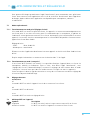
8. DISPLAYS VISUAL | AUDIBLE
8.1 The visual ready signal
This is the blue LED at the "test" key or ready display (16). It lights
up only when the unit is fully charged or discharged. After triggering
a flash, this LED goes out, and lights up again when the unit is fully
charged once more.
The visual ready signal is easy to read even from larger distances. The
brightness (dark / bright) can be altered by the user (see LCD menu
"Brightness test" section 13.16)*.
8.2 The audible ready signal
An acoustic signal (beep) sounds when the power capacitors are 100 % charged, or discharged. The
signal may be switched on or off, and the volume may be regulated*. The corresponding setting
options are explained in LCD menu "Audio ready signal" (section 13.17).
When Scoro power packs are assigned an individual address, the acoustic signal can be pro-
grammed with an individual acoustic (beep) tone*.
8.3 Visual fault signal
In case of a technical fault or activation of the flash monitoring, the test
release key / ready signal (16) lights up red. Should the lamp plug not
be correctly engaged, this will be indicated by the red test release key
and the blinking digital display of the corresponding channel (11).
At the end of their service lives, flash tubes often misfire. This fault is
indicated by the test release key of the Scoro power packs that lights
up red. Additionally, the digital display (11) of the channel to which the
lamp concerned is connected, blinks.
Attention: Check to see if the flash tube is in working order, and change if necessary.
The blinking digital display of the channel concerned can be deactivated by pressing the key "lamp
connection on / off" (7.1, 7.2, 7.3*).
If the fault indication is not caused by the lamp, the power pack must be switched off and on again.
Should the test release key remain red, please contact a broncolor service station.
8.4 Audible fault signal
When the flash discharge fails, a warning signal (two-sound tone) of approx. 0.5 s duration will
sound and the display (11) of the relevant lamp will flash.
* Scoro S only

19
8.5 Audible messages
Clicking tone:
> Key sound (setting of volume is explained in section 13.18).
"Beep" tone:
> End of charging or discharging (setting of volume is explained in section 13.17).
"Double-beep" tone:
> Energy limit top or bottom when controlling energy via RFS / RFS 2 transmitter.
> "reset" key pressed for 2 s (resetting of additional functions).
> "reset" key pressed for 10 s (reset to factory settings).
"Two-sound" tone:
> Technical fault. Ready signal (16) lights red.
> Flash monitoring. The display of the lamp which has not fired lights up.
> Beginning and end of a thermal blocking procedure. Display in LCD.
> A suggestion appears on the LCD when setting changes are not possible with the previous
specifications.
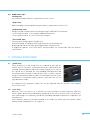
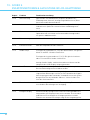
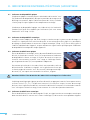
9. SPECIAL FUNCTIONS
9.1 "speed" key*
Flash duration t 0.1 and charge time are reduced by pressing the
"speed" key (17). Therefore, Scoro power packs are optimised for the
shooting of moving objects and / or fast image sequences. As soon as
the "speed" key is activated, the corresponding LED lights blue and
the
maximum flash energy is reduced from 1600 J to 1200 J, and the
energy
is reduced from 3200 J to 2400 J. In speed operation, the colour
temperature is fractionally colder, however, consistent over the en-
ergy adjustment range.
The display of the maximum output (12) can be adjusted with the function "max. display"
(see section 13.21).
9.2 "user" key*
When the "user" key (18) is "on" it activates the initial settings of a further operator. With this,
Scoro S power packs can be individually configured for two users in which all the relevant func-
tions and settings are separately stored, thus providing independent preference capabilities for
multiple users.
Those functions, which are stored in standard or user mode, are shown in the two columns "Mem"
(memory) and "Standard / User" in chapter 13.
* Scoro S only

20
9.3 Memory functions*
In standard and user mode, there are four memories each. All the
unit settings can be stored therein (see LCD function "memory 1 – 4"
section 13.20). Selecting one of the four memories redirects to an in-
formation window in the LCD, in which the most important data of the
corresponding memory are indicated. Pressing the "recall" key reini-
tializes the data in the memory. Pressing the "store" key overwrites
the memory contents with the latest unit settings.
Those functions, which are stored in standard or user mode, are
shown in the two columns "mem" (memory) and "Standard / User" in
chapter 13.
9.4 Freemask / Alternate release*
With the Freemask function of Scoro S it is possible to generate a freemask. For this purpose
two power packs are released asynchronously, for the background and the object to be isolated
(section 13.8).
Alternate release enables to realise even faster shooting sequences. Alternate release also enables
shorter sequences, up to four times faster, even with higher energy (see LCD function "Alternate",
section 13.9). With the same function it is possible to reduce the interval of stroboscopic sequences
down to a minimum of 0.01 s (section 13.6).
9.5 Easy mode*
You can minimize the operating display due turn on the easy mode. Please read the following
instructions:
> Press the "user" key (18) for 5 s. The menu skips to the program setting "easy mode".
> Activate or deactivate the easy mode by pressing "on" respectively "off".
> Turn off and turn on the unit. The easy mode is now activated.
9.6 "reset" key Scoro S
> Brief pressure on the "reset" key (19) advances the cursor directly to the main page. When press-
ing the "menu" key (22) the cursor returns to the beginning of the main menu.
> Pressing this key for approximately 2 s resets the flash additional functions. This is confirmed by
a double-beep tone.
> Pressing this key for approximately 10 s resets all the functions to the factory settings. This is
confirmed by a double-beep tone.
9.7 Reset Scoro E
Press the "test" key (16) for 4 s. The unit will reset all the functions to the factory settings.
9.8 Submenu Scoro E
To reach the submenu of the Scoro E please press the "menu" key (22) for 4 s. The correspondent
functions will be more explained in chapter 14.
* Scoro S only
La page est en cours de chargement...
La page est en cours de chargement...
La page est en cours de chargement...
La page est en cours de chargement...
La page est en cours de chargement...
La page est en cours de chargement...
La page est en cours de chargement...
La page est en cours de chargement...
La page est en cours de chargement...
La page est en cours de chargement...
La page est en cours de chargement...
La page est en cours de chargement...
La page est en cours de chargement...
La page est en cours de chargement...
La page est en cours de chargement...
La page est en cours de chargement...
La page est en cours de chargement...
La page est en cours de chargement...
La page est en cours de chargement...
La page est en cours de chargement...
La page est en cours de chargement...
La page est en cours de chargement...
La page est en cours de chargement...
La page est en cours de chargement...
La page est en cours de chargement...
La page est en cours de chargement...
La page est en cours de chargement...
La page est en cours de chargement...
La page est en cours de chargement...
La page est en cours de chargement...
La page est en cours de chargement...
La page est en cours de chargement...
La page est en cours de chargement...
La page est en cours de chargement...
La page est en cours de chargement...
La page est en cours de chargement...
La page est en cours de chargement...
La page est en cours de chargement...
La page est en cours de chargement...
La page est en cours de chargement...
La page est en cours de chargement...
La page est en cours de chargement...
La page est en cours de chargement...
La page est en cours de chargement...
La page est en cours de chargement...
La page est en cours de chargement...
La page est en cours de chargement...
La page est en cours de chargement...
La page est en cours de chargement...
La page est en cours de chargement...
La page est en cours de chargement...
La page est en cours de chargement...
La page est en cours de chargement...
La page est en cours de chargement...
La page est en cours de chargement...
La page est en cours de chargement...
La page est en cours de chargement...
La page est en cours de chargement...
La page est en cours de chargement...
La page est en cours de chargement...
La page est en cours de chargement...
La page est en cours de chargement...
La page est en cours de chargement...
La page est en cours de chargement...
La page est en cours de chargement...
La page est en cours de chargement...
La page est en cours de chargement...
La page est en cours de chargement...
La page est en cours de chargement...
La page est en cours de chargement...
La page est en cours de chargement...
La page est en cours de chargement...
La page est en cours de chargement...
La page est en cours de chargement...
La page est en cours de chargement...
La page est en cours de chargement...
La page est en cours de chargement...
La page est en cours de chargement...
-
 1
1
-
 2
2
-
 3
3
-
 4
4
-
 5
5
-
 6
6
-
 7
7
-
 8
8
-
 9
9
-
 10
10
-
 11
11
-
 12
12
-
 13
13
-
 14
14
-
 15
15
-
 16
16
-
 17
17
-
 18
18
-
 19
19
-
 20
20
-
 21
21
-
 22
22
-
 23
23
-
 24
24
-
 25
25
-
 26
26
-
 27
27
-
 28
28
-
 29
29
-
 30
30
-
 31
31
-
 32
32
-
 33
33
-
 34
34
-
 35
35
-
 36
36
-
 37
37
-
 38
38
-
 39
39
-
 40
40
-
 41
41
-
 42
42
-
 43
43
-
 44
44
-
 45
45
-
 46
46
-
 47
47
-
 48
48
-
 49
49
-
 50
50
-
 51
51
-
 52
52
-
 53
53
-
 54
54
-
 55
55
-
 56
56
-
 57
57
-
 58
58
-
 59
59
-
 60
60
-
 61
61
-
 62
62
-
 63
63
-
 64
64
-
 65
65
-
 66
66
-
 67
67
-
 68
68
-
 69
69
-
 70
70
-
 71
71
-
 72
72
-
 73
73
-
 74
74
-
 75
75
-
 76
76
-
 77
77
-
 78
78
-
 79
79
-
 80
80
-
 81
81
-
 82
82
-
 83
83
-
 84
84
-
 85
85
-
 86
86
-
 87
87
-
 88
88
-
 89
89
-
 90
90
-
 91
91
-
 92
92
-
 93
93
-
 94
94
-
 95
95
-
 96
96
-
 97
97
-
 98
98


Broncolor Scoro S Le manuel du propriétaire
- Taper
- Le manuel du propriétaire
- Ce manuel convient également à
dans d''autres langues
- English: Broncolor Scoro S Owner's manual
- Deutsch: Broncolor Scoro S Bedienungsanleitung
Documents connexes
-
Broncolor Scoro A2 / A4 Le manuel du propriétaire
-
-
-
-
-
-
-
-
-
Autres documents
-
Elinchrom EL26647 Mode d'emploi
-
Elinchrom Litemotiv 120 & 190 Manuel utilisateur
-
 Elinca Digital RX Manuel utilisateur
-
Elinchrom Zoom Pro HD Manuel utilisateur
-
-
Profoto 300 Manuel utilisateur
-
-
