Sirona SUROTorque L+ Operating Instructions Manual
- Taper
- Operating Instructions Manual

båÖäáëÜLcê~å´~áë
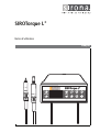
pfolqçêèìÉ=i
H
léÉê~íáåÖ=fåëíêìÅíáçåë=
kçíáÅÉ=ÇDìíáäáë~íáçå=
Motor Speed
Motor Speed
Gear Ratio
Gear Ratio
1 2
Endo
3
SIROTorque L
SIROTorque L
+
BL
BL ISO

Sirona Dental Systems GmbH
Operating Instructions / Notice d'utilisation SIROTorque L
+
60 52 208 D 3489
2 D 3489.201.01.03.07

båÖäáëÜ
pfolqçêèìÉ=i
H
léÉê~íáåÖ=fåëíêìÅíáçåë=
Motor Speed
Motor Speed
Gear Ratio
Gear Ratio
1 2
Endo
3
SIROTorque L
SIROTorque L
+
BL
BL ISO

General information Sirona Dental Systems GmbH
Operating Instructions SIROTorque L
+
60 52 208 D 3489
2 D 3489.201.01.03.02
General information
Dear customer, Thank you for purchasing a SIROTorque L
+
unit from
Sirona.
The technical documentation supplied is also part of the
product. You should always keep this documentation
within reach.
Please read these operating instructions carefully to
familiarize yourself with your SIROTorque L
+
.
Please observe also the Operating Instructions of the
corresponding electric motor and of the straight and
contra-angle handpieces.
If, having carefully studied the operating instructions,
you are nevertheless unable to proceed, contact your
local dental depot.
Your SIROTorque L
+
and Instruments Team

Sirona Dental Systems GmbH Contents
Operating Instructions SIROTorque L
+
60 52 208 D 3489
D 3489.201.01.03.02
3
båÖäáëÜ
Contents
1 Warning and safety information ................................................................................ 5
2 Technical description ................................................................................................. 7
3 Controls and functional elements ............................................................................. 9
4 Installing and connecting the unit............................................................................. 10
5 Operation ..................................................................................................................... 13
6 Error messages ........................................................................................................... 18
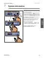
7 System information..................................................................................................... 19
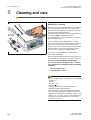
8 Cleaning and care ....................................................................................................... 20
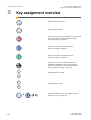
9 Key assignment overview .......................................................................................... 22
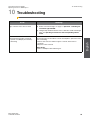
10 Troubleshooting .......................................................................................................... 23

Contents Sirona Dental Systems GmbH
Operating Instructions SIROTorque L
+
60 52 208 D 3489
4 D 3489.201.01.03.02

Sirona Dental Systems GmbH 1 Warning and safety information
Operating Instructions SIROTorque L
+
60 52 208 D 3489
D 3489.201.01.03.02
5
båÖäáëÜ
1 Warning and safety information
Intended use The SIROTorque L
+
was developed for the purpose of
converting the compressed air emitted by a dental treat-
ment center into electrical energy. A dental handpiece
can be powered by this energy. The electric motor of the
SIROTorque L
+
(motor BL (4) or motor BL ISO (5))
replaces the air drive port (for highspeed handpieces or
air-driven motors) previously used on the dental treat-
ment center.
Implantology is not permisible!
Endodontics are permissible only in connection
with a SIRONiTi contra-angle handpiece!
SIROTorque L
+
complies with the latest regulations
reflecting the current state of the art. According to the
regulations, this product may only be used for the
described application by trained personnel, in compli-
ance with the applicable occupational safety regulations
and accident prevention measures as well as the
present operating instructions.
According to these regulations, users are obliged to use
only faultless materials, to ensure correct application
and to protect themselves, the patient and other persons
against hazards.
This unit is not intended for operation in areas subject
to explosion hazards.
General safety information As manufacturers of dental medical equipment and in
the interest of the operational safety of your system, we
stress the importance of having maintenance and
repair of this product performed only by Sirona Dental
Systems or by agencies expressly authorized by Sirona
Dental Systems. Furthermore components must always
be replaced with original spare parts upon failure.
When having such work done, we suggest that you
request
a certificate stating the type and extent of work
performed, including
information about any modifica-
tions of the rated parameters or of the operating ranges
(if applicable), as well as the date, name of organization
and signature.
Modifications to this system which might affect the safety
of the system owner, patients or other persons are pro-
hibited by law!
For reasons of product safety, this product may be oper-
ated only with original Sirona accessories or third-party
accessories expressly approved by Sirona. The user is
responsible for any damage resulting from the use of
non-approved accessories.

1 Warning and safety information Sirona Dental Systems GmbH
Operating Instructions SIROTorque L
+
60 52 208 D 3489
6 D 3489.201.01.03.02
It is not permitted to modify the design or construction of
the unit.
The system owner is obliged to use only technically
faultless products. Prior to engaging the system into ser-
vice, its proper functioning must be checked. In case of
unusual noises, please check the unit, electric motor and
straight/contra-angle handpiece.
The unit is not sterile.
Please observe the operating instructions for the rele-
vant electric motors.
NOTE
i
When the supply voltage drops for a moment, you must
reckon with a brief speed reduction.
Wireless phone interference with dental electrical
equipment
To ensure safe operation of medical electrical equip-
ment, the use of mobile wireless phones in practice or
hospital environments must be prohibited.
Highlighting of warning and safety information To avoid personal injury and material damage, you must
also observe the warning and safety information pro-
vided in the present operating instructions. All such infor-
mation is highlighted by the signal words NOTE,
CAUTION or WARNING.
Symbols used Observe accompanying documents!
Disposal It generally applies that any disposal of this product must
comply with the relevant national regulations.
Please observe the regulations applicable in your coun-
try.
Within the European Economic Community, Council
Directive 2002/96/EU (WEEE) requires environmentally
sound recycling/disposal of electrical and electronic
devices.
Your product is marked with the adjacent symbol.
Disposal of your product with domestic refuse is not
compatible with the objectives of environmentally sound
recycling/disposal.
The black bar underneath the "garbage can" symbol
means that it was put into circulation after Aug. 13, 2005
(see EN 50419:2005).
Please note that this product is subject to Council
Directive 2002/96/EU (WEEE) and the applicable
national law of your country and must be recycled or dis-
posed of in an environmentally sound manner.
Please contact your dealer if final disposal of your prod-
uct is required.
The unit must be disinfected prior to disposal!
CAUTION According to US Federal Law, this product may be sold
only to or by instruction of dentists, general medical
practitioners and medical specialists.
i

Sirona Dental Systems GmbH 2 Technical description
Operating Instructions SIROTorque L
+
60 52 208 D 3489
D 3489.201.01.03.02
7
båÖäáëÜ
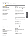
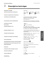
2 Technical description
Model designation SIROTorque L
+
Transformer primary voltage 120 V∼ 50/60 Hz 120 V~ 60 Hz 230 V∼ 50 Hz
TIYM 24 - 02 M TDYN - 01 M TIYE 24 - 02 M
100 VA 75 VA 100 VA
Transformer secondary voltage 24 VAC
Cooling air pressure Nominal operating pressure: 44 psi (3 bar),
maximum operating pressure: 73 psi (5 bar)
depending on control pressure
ISO 4-hole connection
Cooling air consumption Depending on control pressure (min. 18 NL/min,
at nominal operating pressure of 44 psi (3 bar))
Spray air pressure 2.7 + 0.1 bar
Spray water 2 + 0.1 bar, min. 100 ml/min
Air requirements Dry, oil-free, dirt-free, not contaminated.
If necessary: Use compressor with dry air system, install
air filter (50 µ), blow through hoses before connnecting
them.
Water requirements The spray water must be dirt-free according to the appli-
cable regulations. It must not be contaminated.
Operating conditions Ambient temperature: 50 °F – 104 °F (10 °C – 40 °C)
Relative humidity: 30 % – 75 %
Air pressure: 700 hPa – 1060 hPa
Transport and storage conditions Temperature: -40 °F – 158 °F (-40 °C – +70 °C)
Relative humidity: 10 % – 95 %
Air pressure: 500 hPa – 1060 hPa
Protection class Protection class I
Degree of protection against electric shock Type B applied parts
Degree of protection against ingress of water Ordinary equipment (not protected)
Mode of operation Intermittent operation 60 s, 10 min pause
(“INT 1/10 MIN“)
Dimensions Width: 150 mm, depth: 130 mm, height: 70 mm
Weight (without electric motor and hose) approx. 560 g
Weight of transformer approx. 2300 g
Year of manufacture (on rear side of unit)
OMuu

2 Technical description Sirona Dental Systems GmbH
Operating Instructions SIROTorque L
+
60 52 208 D 3489
8 D 3489.201.01.03.02
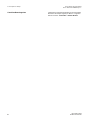
Tests/approvals This unit is intended exclusively for operating electric
motors approved by Sirona. This applies to: BL motor
and BL ISO motor

Sirona Dental Systems GmbH 3 Controls and functional elements
Operating Instructions SIROTorque L
+
60 52 208 D 3489
D 3489.201.01.03.02
9
båÖäáëÜ
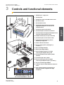
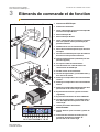
3 Controls and functional elements
1. SIROTorque L
+
supply unit
2. Control panel
3. Supply hose for BL or BL ISO electric motor
4. BL electric motor
5. BL ISO electric motor
6. Supply hose of an air-driven instrument
(highspeed handpiece, air motor) of the
treatment center
7. Connecting cable to transformer
8. Connection piece for electric motor hose
9. Connection piece for highspeed handpiece or air
motor hose from treatment center
10. ON/OFF switch (only for a part of the unit)
11. Connection piece for transformer cable
12. Transformer with connecting cable to
SIROTorque supply unit
13. Power cable for transformer
14. Keys for setting motor speed higher (+)
or lower (–)
15. Burr speed digital display
16. Motor speed digital display
17. Gear ratio digital display for straight/
contra-angle handpiece being used
18. Counterclockwise motor rotation symbol
(flashes)
19. Instrument light "ON" symbol
20. Keys for setting gear ratio of straight/
contra-angle handpiece higher (+) or lower (–)
21. Key for instrument light ON/OFF
22. "Reverse" key for counterclockwise rotation of
motor
23. Four colored save keys for presettings of
differently colored straight/contra-angle
handpieces
Motor Speed Gear Ratio
1 2
Endo
3
SIROTorque L
+
Motor Speed Gear Ratio
Bur Speed
5
Sirona Dental System
sGmbH
Fabrikstraße
31
D-64625
Bensheim
Germ
any
Sirona
Dental
Systems
GmbH
Fabrikstraße
31
D-64625
Bensheim
Germany
TIYE24-02M (230V)
TIYE24-02M
(230V)
TIYM24-02M (120V)
TIYM24-02M
(120V)
0123
1
2
3 64
5
7
3
6
7
8
9
13
14 15 16 20 21 22
12
18 2319
10
11
17

4 Installing and connecting the unit Sirona Dental Systems GmbH
Operating Instructions SIROTorque L
+
60 52 208 D 3489
10 D 3489.201.01.03.02
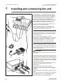
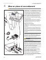
4 Installing and connecting the unit
The SIROTorque L
+
was developed for the purpose
of converting the compressed air emitted by a dental
treatment center into electrical energy. A straight/con-
tra-angle dental handpiece can be powered by this
energy. The electric motor of the SIROTorque L
+
(motor BL (4) or motor BL ISO (5)) replaces the air drive
port (for highspeed handpieces or air-driven motors)
previously used on the dental treatment center.
It is connected and controlled solely via the hose cou-
pling (6a) of the air-driven instrument.
Control is effected by means of the pneumatic foot
switch (A) which is available on the unit side. Power
is supplied by an external transformer (12).
Site of installation
Mount the SIROTorque L
+
(1) at an easily accessible
location on top of or adjacent to the dentist element of
the treatment center.
Be sure to choose the installation site of the
SIROTorque L
+
so that the SIROTorque L
+
can easily be
connected to the dentist element with the previously
used highspeed handpiece or air motor hose (6).
Ensure that the unit has a safe and stable stand.
Connection
Detach the highspeed handpiece, quick coupling or air
motor used until now from the supply hose and plug con-
nection piece (6a) into the four-hole connection (9) on
the rear side of the unit.
ATTENTION
With a 5-hole hose, remove the lamp from the hose prior
to operation.
Fit the electric motor hose (3) to the connection piece (8)
on the rear side of the SIROTorque L
+
. Attach the corre-
sponding electric motor to the motor hose (see Operat-
ing Instructions of motor). Place the motor in the holder
on the dentist element which was previously occupied by
the air-driven instrument.
Connect the connector of the transformer connecting
cable (7) to the connection piece (11) of the
SIROTorque L
+
.
Plug the power cable (13) into the transformer.
All cables must be safely routed, avoid stumbling
hazards!
Plug the transformer power plug into a grounded socket
outlet.
Do not use any transformer other than the one approved
and supplied by Sirona, i.e. TIYM24-02M (120 V) or
TDYN-01M (120V) or TIYE24-02M (230 V)!
5
Siro
n
a
D
e
n
ta
l
Sy
ste
m
s
G
m
b
H
Fa
b
rikstraß
e
3
1
D
-6
4
6
2
5
B
e
n
sh
e
im
G
e
rm
a
n
y
Sirona
Dental
Systems
GmbH
Fabrikstraße
31
D-64625
Bensheim
Germany
TIYE24-02M
(230V)
TIYE24-02M
(230V)
TIYM24-02M
(120V)
TIYM24-02M
(120V)
0123
1
3
4
12
5
6
6a
9
A
8
3
7
7
11
13

Sirona Dental Systems GmbH 4 Installing and connecting the unit
Operating Instructions SIROTorque L
+
60 52 208 D 3489
D 3489.201.01.03.02
11
båÖäáëÜ
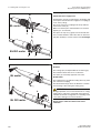
Supplementary notes for installing
SIROTorque L
+
The connecting cable (7) between the transformer (12)
and the SIROTorque L
+
(1) must be run in such a way
that it can not be damaged by moving appliances such
as chairs with wheels, carts, etc.:
• Place the transformer (12) directly next to the supply
unit (C).
• Run the connecting cable (7) so that it does not
touch the floor anywhere. To do this, use the
adhesive cable clamps (D) supplied.
• Run the connecting cable (7) in such a way that it
cannot be damaged at the supply unit.
• Install the power cable (13) of the transformer as
required by the relevant national regulations.
Satellite version
Upon your request, the supplied SIROTorque L
+
table-
top unit may be converted to a "satellite version" by your
service engineer.
Conversion kit, Order No: 60 57 223
In this version, the control panel is separated from the
SIROTorque L
+
tabletop unit and is connected to the
latter by a permanently wired cable having a length of
approx. 3 m.
The control panel (A) can be fastened at a place that is
easily accessible for the user, e.g. in the control panel
front area, either with screws (from the top) or with the
Velcro strap included in the scope of supply (from the
front).
Fastening of the control panel is done at your own risk,
make sure not to damage any cables etc. with the
screws.
The SIROTorque L
+
supply unit (B) can be installed
e.g. below the dentist element.
Establish all connections as described under
"Connection".
ATTENTION
Repair and maintenance work on the SIROTorque L
+
must be performed only by properly trained service engi-
neers. Before opening the housing, pull the power plug or
disconnect all poles from the power supply so as to deen-
ergize the unit. Wait for at least 10 seconds.
The compressed air delivered by the highspeed hand-
piece or air motor hose must be dry, oil-free and dirt-free.
It must not be contaminated!
If necessary, install a filter or water separator.
The spray water must be dirt-free according to the appli-
cable regulations. It must not be contaminated.
5
Siro
na
D
ental
Syste
m
s
G
m
bH
Fab
rikstraß
e
3
1
D
-6
46
2
5
Ben
sheim
G
erm
a
ny
Sirona
Dental
Systems GmbH
Fabrikstraße
31
D-64625
Bensheim
Germany
T
IY
E
2
4
-0
2
M
(2
3
0
V
)
TIYE24-02M
(230V)
T
IY
M
2
4
-0
2
M
(1
2
0
V
)
TIYM24-02M
(120V)
0123
120V/60Hz
A
B
7
C
12
1
D
13

4 Installing and connecting the unit Sirona Dental Systems GmbH
Operating Instructions SIROTorque L
+
60 52 208 D 3489
12 D 3489.201.01.03.02
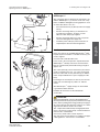
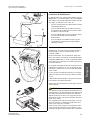
Connecting the BL or BL ISO electric motor
Connection to the supply hose
Push back the cap nut (1) and insert the small tubes and
contact pins of the motor in the supply hose coupling (2)
as far as they will go.
The arrow on the hose coupling must line up with the
notch on the motor (A).
Make sure that the pins and small tubes are inserted
properly (i.e. are not bent).
First press the cap nut (1) gently onto the thread; then
turn it counterclockwise until a faint click can be heard.
Only then should you screw it onto the motor hand-tight.
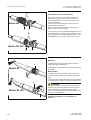
Adjusting the cooling spray
BL motor
The cooling spray is adjusted with the control ring (3).
The maximum water flow rate is set when the
two marks (4) are lined up opposite each other.
BL ISO motor
The cooling spray is set with the rotating sleeve (5) at the
rear of the hose coupling.
The threshold arrow (6) shows the direction of rotation
for increasing or decreasing the cooling spray.
ATTENTION
During preparation work, a sufficient amount of cooling
media (water component > 50 ml/min) must always be
available. Insufficient cooling leads to overheating of the
cavity and to damage to the tooth substance.
Please always make sure that the flow rate is
sufficient!
12
1
BL motor
BL ISO motor
A
A
2
max
3
4
5
6
BL motor
BL ISO motor

Sirona Dental Systems GmbH 5 Operation
Operating Instructions SIROTorque L
+
60 52 208 D 3489
D 3489.201.01.03.02
13
båÖäáëÜ
5 Operation
ATTENTION
Make sure that the compressed air is always dry, clean
and not contaminated. Dirty or humid compressed air
leads to premature wear of the motor.
Permissible speed range: 90 – 40,000 rpm
The compressed air emitted at the highspeed handpiece
hose connection piece should have a pressure of
at least 44 psi (3 bar) to enable the electric motor to
reach its maximum speed.
ATTENTION
The displayed speed is an approximate value. The actual
speed may differ from the displayed speed.
If you need an accurate speed, you should operate the
motor at a speed close to 40,000 rpm and use the corre-
sponding contra-angle handpieces.
e.g. desired speed: 347 rpm.
– Set motor to 40,000 rpm.
– Use reduction gear instrument (115 : 1).
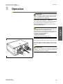
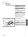
Switching the unit on
with the ON/OFF switch (10) on the rear side of the unit.
The display lights up and the settings of the last hand-
piece used appear (even if they deviate from the stored
values).
ATTENTION
This unit offers a higher power output than a highspeed
handpiece. You should practice treatment on a phantom
element before using it on a patient.
5
Sirona
D
ental System
sG
m
bH
Fabrikstraße
31
D-64625
Bensheim
G
erm
any
Sirona
Dental
Systems
GmbH
Fabrikstraße
31
D-64625
Bensheim
Germany
TIYE24-02M (230V)
TIYE24-02M
(230V)
TIYM24-02M (120V)
TIYM24-02M
(120V)
0123
10

5 Operation Sirona Dental Systems GmbH
Operating Instructions SIROTorque L
+
60 52 208 D 3489
14 D 3489.201.01.03.02
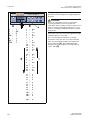
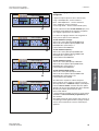
Setting the gear ratio
Attach the selected straight/contra-angle handpiece to
the motor.
ATTENTION
Be sure to compare the gear ratio of the straight/
contra-angle handpiece you're using with the
"Gear Ratio" display reading. If these two values are not
identical, the burr speed display reading is not correct,
since it is calculated by multiplying the motor speed by
the gear ratio.
Set the gear ratio of the attached straight/contra-angle
handpiece with the +/- keys (20).
This is also possible when the motor is running.
Preselection of the gear ratio occurs in the following
order. The most popular straight/contra-angle hand-
pieces appear first
(A). Then additional possible
straight/contra-angle handpieces are displayed from
1:0.5 to 199:9
(B).
Motor Speed Gear Ratio
1 2
Endo
3
SIROTorque L
+
Motor Speed Gear Ratio
Bur Speed
20
1:1
1:4.2
1:5
2.4 : 1
6:1
24 : 1
115 : 1
1:0.5
1:1
1:1.5
1:2
1:2.5
1:3
–
1:9
1:9.5
1.5 : 1
1.5 : 1.5
1.5 : 2
1.5 : 2.5
1.5 : 3
–
1.5 : 9.5
2:1
2:1.5
2:2
–
2:9.5
–
10 : 1
10 : 1.5
10 : 2
10 : 2.5
–
11 : 1
11 : 2
11 : 3
11 : 4
–
11 : 9
12 : 1
12 : 2
12 : 3
12 : 9
–
199 : 1
199 : 2
199 : 3
–
199 : 9
A
B
–
+

Sirona Dental Systems GmbH 5 Operation
Operating Instructions SIROTorque L
+
60 52 208 D 3489
D 3489.201.01.03.02
15
båÖäáëÜ
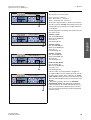
Recalling stored handpiece settings
The unit has four save keys (23)
Red – Gear ratio, save key 1
Blue – Gear ratio 1:1, save key 2
Green – Reduction ratio, save key 3
Endo contra-angle handpiece – Endo save key (black)
After the respective save key (23) is briefly pressed, the
corresponding stored settings are recalled and shown
on the display.
The following values and settings are stored in the save
keys at the factory:
Save key 1 (red):
Burr speed 200,000 rpm
Motor speed 40,000 rpm
Gear ratio 1:5
Instrument light ON
Save key 2 (blue):
Burr speed 40,000 rpm
Motor speed 40,000 rpm
Gear ratio 1:1
Instrument light ON
Save key 3 (green):
Burr speed 1,000 rpm
Motor speed 6,000 rpm
Gear ratio 6:1
Instrument light ON
Endo save key (black):
Burr speed 347 rpm
Motor speed 40,000 rpm
Gear ratio 115:1
Instrument light OFF
If the foot switch is actuated while the straight/con-
tra-angle handpiece is removed from its holder, the elec-
tric motor starts running. At the same time, the actual
motor speed and burr speed as well as the preselected
gear ratio of the handpiece being used are shown on the
display.
If the pedal is pressed to the floor, the maximum
programmed speed is then displayed and attained.
If the air supply can be variably adjusted with the foot
switch, the speed and the displayed speed value will
also vary between the minimum and the programmed
maximum speed.
Motor Speed Gear Ratio
1 2
Endo
3
SIROTorque L
+
Motor Speed Gear Ratio
Bur Speed
Motor Speed Gear Ratio
1 2
Endo
3
SIROTorque L
+
Motor Speed Gear Ratio
Bur Speed
Motor Speed Gear Ratio
1 2
Endo
3
SIROTorque L
+
Motor Speed Gear Ratio
Bur Speed
Motor Speed Gear Ratio
1 2
Endo
3
SIROTorque L
+
Motor Speed Gear Ratio
Bur Speed
23
23
23
23

5 Operation Sirona Dental Systems GmbH
Operating Instructions SIROTorque L
+
60 52 208 D 3489
16 D 3489.201.01.03.02
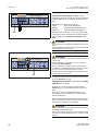
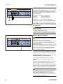
Adjusting the speed
Using the two "Motor Speed" +/– keys (14), the
recalled speed can be manually increased or decreased
and then indicated as the maximum speed on the dis-
play.
Adjustment is possible in increments of:
10 rpm – between 90 and 400 rpm
200 rpm – between 400 and 5,000 rpm and
1,000 rpm – between 5,000 and 40,000 rpm
The speed last set with the +/– keys (14) is preserved
even after the unit is switched OFF and back ON again
if the foot switch was previously actuated at least
once.
ATTENTION
The speed can be changed even while the motor is run-
ning.
The instrument must not be in the patient’s mouth when a
speed adjustment is performed.
Reversal of rotation
ATTENTION
From your carbide burs, you may be used to clockwise
rotation only.
Please note that your new electric motor can also be
operated counterclockwise.
Prior to switching to counterclockwise rotation, make
sure that the contra-angle handpiece and the respective
inserts used can be operated counterclockwise
(Caution: Contra-angle handpiece for prophylaxis must
be operated clockwise only!).
To switch the electric motor to counterclockwise rotation,
press the "Reverse" key (22).
Counterclockwise rotation is signaled by the flashing
CCW arrow on the display.
Changeover to counterclockwise rotation with the
"Reverse" key is also possible while the motor is run-
ning.
In this case, the motor gradually runs down in the
selected direction of rotation before starting up again
in the other direction.
After the unit is switched OFF and back ON again, the
motor is automatically reset to clockwise rotation and the
flashing arrow disappears on the display.
ATTENTION
The instrument must not be in the patient’s mouth when a
speed adjustment is performed.
Prior to each motor start, please check to make sure the
motor has not inadvertently been set to counterclockwise
rotation!
Motor Speed Gear Ratio
1 2
Endo
3
SIROTorque L
+
Motor Speed Gear Ratio
Bur Speed
14
Motor Speed Gear Ratio
1 2
Endo
3
SIROTorque L
+
Motor Speed Gear Ratio
Bur Speed
22

Sirona Dental Systems GmbH 5 Operation
Operating Instructions SIROTorque L
+
60 52 208 D 3489
D 3489.201.01.03.02
17
båÖäáëÜ
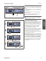
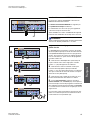
Instrument light OFF/ON
With key (21) you can switch the instrument light OFF
and ON.
Instrument light ON is signaled by the lamp symbol
on the display.
Changeover with key (21) is also possible while the
motor is running.
After the unit is switched OFF and back ON again,
the last lamp status set remains saved.
NOTE
i
After the foot switch is released, the instrument light
illuminates for approx. 1 second.
Programming handpiece settings
The gear ratio, motor speed and instrument light status
(ON/OFF) can all be reprogrammed together. If you
want to overwrite the factory-programmed values and
settings in the four program keys, proceed as follows:
A – Select the gear ratio of the required straight/
contra-angle handpiece using the +/– keys (20).
This value then appears on the display.
B – Select the desired maximum motor speed with the
+/– keys (14). This value then appears on the display,
and also determines the value of the burr speed.
C – Use key (21) to determine whether or not the instru-
ment light should be switched on.
D – To program the new values, press the respective
save key (1, 2, 3 or Endo) (23) (in the example shown
here, it would be advisable to press green program key 3
due to the preselected reduction ratio) > 3 seconds.
The new setting is confirmed by a brief acoustic signal.
The newly programmed values can be recalled when-
ever required by briefly pressing the corresponding
save key (23).
Motor Speed Gear Ratio
1 2
Endo
3
SIROTorque L
+
Motor Speed Gear Ratio
Bur Speed
21
Motor Speed
Gear Ratio
1 2
Endo
3
SIROTorque L
+
Motor Speed Gear Ratio
Bur Speed
A
Motor Speed Gear Ratio
1 2
Endo
3
SIROTorque L
+
Motor Speed Gear Ratio
Bur Speed
B
Motor Speed Gear Ratio
1 2
Endo
3
SIROTorque L
+
Motor Speed Gear Ratio
Bur Speed
C
Motor Speed Gear Ratio
1 2
Endo
3
SIROTorque L
+
Motor Speed Gear Ratio
Bur Speed
D
>3 s
20
14
21
23

6 Error messages Sirona Dental Systems GmbH
Operating Instructions SIROTorque L
+
60 52 208 D 3489
18 D 3489.201.01.03.02
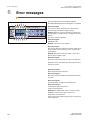
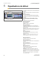
6 Error messages
Errors are indicated on the "Bur Speed" display.
The display illumination flashes during the error display.
Error message F1
The motor has been switched off for safety reasons
(overheating or insufficient supply voltage).
Remedy: Remove your foot from the foot switch and
wait for approx. 1 minute until "F1" disappears from the
display.
The unit is ready for operation.
Error message F2
"EEPROM" error
Remedy: Call your service engineer.
Error message F3
The unit was disconnected from the power supply while
the foot switch was pressed (e.g. loose contact, brief
power failure).
Remedy: Remove foot from foot switch, ensure trou-
ble-free power supply, restart.
Error message F5
No motor connected or motor or motor hose defective.
Remedy: Connect motor properly; replace motor hose or
motor if necessary.
Error message F11
Short-circuit protection activated.
Error message F12
Electrical connection between motherboard and motor
too weak.
Error message F13
Position detection of turbine in motor defective.
Error message F14
Overcurrent in motor lamp circuit.
Lamp or motor defective.
Remedy F11 – F14: Switch unit off, check for proper
installation of motor incl. lamp or motor hose.
Then switch the unit back on.
If the error message appears again, please contact your
service engineer.
Motor Speed Gear Ratio
1 2
Endo
3
SIROTorque L
+
Motor Speed Gear Ratio
Bur Speed
La page charge ...
La page charge ...
La page charge ...
La page charge ...
La page charge ...
La page charge ...
La page charge ...
La page charge ...
La page charge ...
La page charge ...
La page charge ...
La page charge ...
La page charge ...
La page charge ...
La page charge ...
La page charge ...
La page charge ...
La page charge ...
La page charge ...
La page charge ...
La page charge ...
La page charge ...
La page charge ...
La page charge ...
La page charge ...
La page charge ...
La page charge ...
La page charge ...
La page charge ...
La page charge ...
La page charge ...
La page charge ...
-
 1
1
-
 2
2
-
 3
3
-
 4
4
-
 5
5
-
 6
6
-
 7
7
-
 8
8
-
 9
9
-
 10
10
-
 11
11
-
 12
12
-
 13
13
-
 14
14
-
 15
15
-
 16
16
-
 17
17
-
 18
18
-
 19
19
-
 20
20
-
 21
21
-
 22
22
-
 23
23
-
 24
24
-
 25
25
-
 26
26
-
 27
27
-
 28
28
-
 29
29
-
 30
30
-
 31
31
-
 32
32
-
 33
33
-
 34
34
-
 35
35
-
 36
36
-
 37
37
-
 38
38
-
 39
39
-
 40
40
-
 41
41
-
 42
42
-
 43
43
-
 44
44
-
 45
45
-
 46
46
-
 47
47
-
 48
48
-
 49
49
-
 50
50
-
 51
51
-
 52
52


Sirona SUROTorque L+ Operating Instructions Manual
- Taper
- Operating Instructions Manual
dans d''autres langues
- English: Sirona SUROTorque L+
Documents connexes
Autres documents
-
NSK NLZ Mode d'emploi
-
-
-
SciCan STATIS 1.1 ST Operating Instructions Manual
-
 B.A. International BA-Optima BA121T Mode d'emploi
-
Midmark 1000 Dental Delivery System Mode d'emploi
-
SciCan SANAO PSO Instructions For Use Manual
-
EMS PIEZON 250 Operation Instructions Manual
-
-
 MELAG Care Oil Spray Mode d'emploi

