Asco Series 569 570 571 BUSLINK Generation C Le manuel du propriétaire
- Taper
- Le manuel du propriétaire

5
3
1
A
S
I
IN
1
-1
IN
1
-2
P
W
R
IN
1
-3
IN
1
-4
IN
2
-1
IN
2
-2
IN
2
-3
IN
2
-4
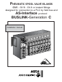
Installation manual
MS-P586-5.GB.R2a
P
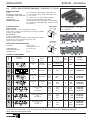
NEUMATIC SPOOL VALVE ISLANDS
ØM5 - G1/8 - G1/4 or instant fittings
designed for connection to a PLC by field bus and
AS-Interface protocol
BUSLINK-Generation C
NTERFACE
N˚ 21401

2
BUSLINK - AS-Interface INSTALLATION
COPYRIGHT © 1999 - 2000 - ASCO/JOUCOMATIC - All rights reserved.
CAUTION
To avoid malfunction of the bus system, please check on any valve island
• for correct addressing parameters.
• all installation, adjustment and maintenance operations must be carried out by qualified personnel.
NOTICE
The information in this manual is subject to change without notice.
In no event shall ASCO/JOUCOMATIC be liable for technical or editorial errors or omissions. Neither is any liability assumed
for accidental or consequential damages arising out of or in connection with the supply or use of the informaton contained
herein.
THIS MANUAL CONTAINS INFORMATION PROTECTED BY COPYRIGHT. NO PART OF THIS DOCUMENT MAY BE
PHOTOCOPIED OR REPRODUCED IN ANY FORM OR MANNER WHATSOEVER WITHOUT PRIOR WRITTEN PERMISSION
FROM JOUCOMATIC.
CONTENTS Page
1. The BUSLINK system - Generation C - with AS-Interface protocol _________________________________ 3
2. System components _______________________________________________________________________ 5
2.1 Functional description ______________________________________________________________ 5
2.2 Component assembly _______________________________________________________________ 5
2.3 Dimensions - Mounting ______________________________________________________________ 6
2.4 Ordering information for a BUSLINK valve island - Generation C - with AS-Interface ______________ 7
2.5 Manual override ___________________________________________________________________ 8
2.6 Spool valves series 569 - 570 - 571 ____________________________________________________ 9
3. Assembly of BUSLINK Generation C with AS-Interface __________________________________________ 10
3.1 Mounting _________________________________________________________________________ 10
3.2 Pneumatic connection ______________________________________________________________ 10
4. Electrical connection ______________________________________________________________________ 12
4.1 General __________________________________________________________________________ 12
4.2 Voltage supply ____________________________________________________________________ 12
4.3 Calculation of power draw ___________________________________________________________ 12
4.4 Connection of inputs ________________________________________________________________ 13
4.5 Addressing of inputs/outputs _________________________________________________________ 14
4.6 Control signals ____________________________________________________________________ 16
5. AS-Interface network ______________________________________________________________________ 18
5.1 Connection of AS-Interface bus (yellow cable) ___________________________________________ 18
5.2 Programming instructions ____________________________________________________________ 18
5.3 Connection of supply voltage (black cable) ______________________________________________ 19
5.4 Startup of AS-Interface network _______________________________________________________ 19
5.5 Diagnostics _______________________________________________________________________ 19
5.6 Fuses ___________________________________________________________________________ 19
5.7 Accessories for AS-Interface _________________________________________________________ 20
5.8 Dimensions of the accessories for AS-Interface __________________________________________ 20
A separate Declaration of Incorporation relating to EEC-Directive 89/392/EEC Annex II B is available on request.
Please provide acknowledgement number and serial numbers of products concerned.
This product complies with the essential requirements of the EMC-Directive 89/336/EEC and amendments. A
separate Declaration of Conformity is available on request.

3
INSTALLATION BUSLINK - AS-Interface
5
3
1
3
2
1
A
S
I
IN
1-
1
IN
1
-2
P
W
R
IN
1
-3
IN
1
-4
IN
2
-1
IN
2
-2
IN
2
-3
IN
2
-4
Max. 8 outputs (valves)
24V =
ASi
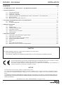
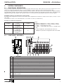
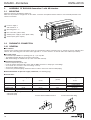
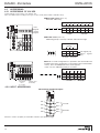
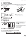
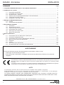
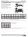
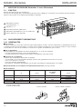
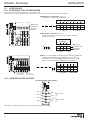
1. The BUSLINK system - generation C - with AS-Interface protocol
Pneumatic islands of 4 to 8 monostable or bistable spool valves, ØM5 - G1/8 - G1/4, with integrated connections for data
exchange with a control system (PLC) by means of a field bus and standardized AS-Interface protocol.
(
*
) Bistable spool valves series 569 - 570 - 571
with
integrated push/pull pilot valves (pilots placed on
one side of the island offering a compact solu-
tion).
ADVANTAGES
With the many advantages it offers, the Buslink system meets modern needs for automated installations.
• No bulky and difficult wiring.
• Time and money saved due to direct electric cabling and common air supply.
• Unit tested and equipped with spool valves at delivery.
• Easy maintenance.
COMBINATIONS
Buslink units can be grouped as follows:
•
Islands of 4, 6 or 8 monostable 3/2, 5/2 or 5/3 spool valves or 4 bistable spool
valves or 4 double 3/2 NC.
•
Differently sized islands for spool valve series 569 - 570 - 571 (only one valve
size per island
).
• Upon request, each island can be equipped with four 5-pin female panel
connectors M12 to connect 4 inputs (1 node configuration) or 8 outputs (2
node configuration).
• Monostable and bistable spool valves with integrated push/pull pilot valves
(
*
), all functions available on one island.
• Any configuration possible upon request.
42
513
14
12
NTERFACE
N˚ 21401
1
Spool valves ( 8 monostable or 4 bistable valves at maximum )
2
Module for AS-Interface connection
3
4 or 8 inputs at option
NOTE - No additional input or output modules available
CONNECTION DIAGRAM
yellow cable
black cable
AS-Interface
supply
AS-Interface
master
AS-Interface bridge to
other protocols
(Profibus-DP, FIPIO,
Device NET, . . .)

4
BUSLINK - AS-Interface INSTALLATION
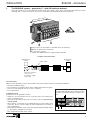
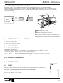
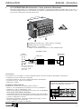
AS-INTERFACE (AS-Interface)
Pneumatic spool valve island for data exchange via field bus
and standardized AS-Interface protocol.
The connection between a control system (PLC) and several spool
valve islands by means of a field bus allows the transmission of data
with a standard AS-Interface cable :
• control signals to the spool valves,
• information signals from the sensor inputs.
ADVANTAGES
With the many advantages it offers, the Buslink system meets
modern needs for automated installations.
• No bulky and difficult wiring.
• Time and money saved due to direct electric cabling and common
air supply.
• Visual display and quick disconnection for easy maintenance.
• Unit tested and equipped with spool valves at delivery.
COMBINATIONS
Buslink units can be grouped as follows:
• Modules for 3/2, 2x3/2, 5/2 or 5/3 spool valves series 569 (ØM5 or
instant fittings) - 570 (G1/8 or instant fittings) - 571 (G1/4).
OPTIONS
• Island with air supplied at two different pressure rates.
• Island with external air supply for pilot pressure.
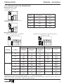
COMMUNICATION CHARACTERISTICS
Communication protocol : AS-Interface (bidirectional mode)
Transmission : flat AS-Interface cable (yellow, 2 wires)
Bus structure : any structure according to AS-Interface standards
Max. number of spool valve islands : 31 nodes (1 valve island can have 2 nodes)
Number of valves per island : 4 to 8
Number of inputs/outputs : 0, 4 or 8 inputs
Max. bus cable length : 100 m (300 m with repeaters)
Island addressing (participants) : AS-Interface master
Compatibility with control system : no modification of current programmes
Compatible equipment : various options
ELECTRICAL CHARACTERISTICS
Supply voltage : 24 V DC, ±10% at the island.
Supply to the valves with an additional flat AS-Interface cable (black, 2 wires).
Max. ripple ratio : 10 %
Consumption : 79 mA per valve and 9 mA per input
Coil insulation class : F
Protection : IP65
Electrical insulation of the inputs : optocouplers
Peak voltage suppression : integrated in the island for each coil
Additional 24 V supply connection : vampire-type panel connector for AS-Interface cable (black cable)
Bus connection (IN/OUT) : vampire-type panel connector for AS-Interface cable (yellow cable)
Input connection : 5-pin female panel connector M12
Earth connection : earthing screw on the pneumatic subbase
Electromagnetic compatibility : in accordance with the EU directive EMC 89/336/EEC
CE identification
PNEUMATIC CHARACTERISTICS
Fluid : air or neutral gas, filtered at 30 µm, lubricated or not
Operating pressure : 1.5 to 8 bar (2.5 to 8 bar with 3/2 NO spool valves and series 569 functions 5/3)
Flow rate (Qv at 6 bar) series 569 : 175 l/min
series 570 : 600 l/min (3/2: 400 l/min - 2x3/2 : 550 l/min)
series 571 : 1050 l/min
Allowable temperature : +5 °C to +50 °C
ACCESSORIES: see following page
5
3
1
A
S
I
IN
1
-1
IN
1
-2
P
W
R
IN
1
-3
IN
1
-4
IN
2
-1
IN
2
-2
IN
2
-3
IN
2
-4
24V =
ASi
yellow cable
black cable
AS-Interface
supply
AS-Interface
master
AS-Interface bridge to other protocols
(Profibus-DP, FIPIO, Device NET etc.)

5
INSTALLATION BUSLINK - AS-Interface
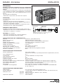
2. SYSTEM COMPONENTS
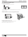
2.1 FUNCTIONAL DESCRIPTION
The spool valve islands are connected to a PLC with a (yellow) AS-Interface bus cable to pilot the spool valves and detect the sensor
status if the island is provided with inputs. A second adapter is used to supply the valves with power (black cable).
The pressure supply and exhaust are collected in the pneumatic subbase. The spool valves ensure the pressure supply and exhaust
of the pneumatic actuators. The pneumatic connection of the actuators is made on the top side of the spool valves. The island can be
equipped with inputs upon request. The electrical sensors are connected to the input modules with male connectors ØM12.
MAXIMUM CAPACITY OF THE SPOOL VALVE ISLAND
According to the configuration you choose, the islands can be equipped with a maximum of 8 inputs and 8 outputs (1 output = 1 spool
valve pilot).
The maximum capacity of the island depends on the number of nodes (see table below).
Example for maximum configuration:
Number
of nodes
Max. number
of valves
Max. number
of inputs
1
4 monostable
or 2 bistable
or 2 double 3/2 NC
4
2
8 monostable
or 4 bistable
or 4 double 3/2 NC
or 4 monostable +
2 bistable (1)
8
NOTE:
- Maximum configuration for 1 node
: 4 outputs / 4 inputs
- Maximum configuration for 2 nodes: 8 outputs / 8 inputs
- 1 output = 1 monostable spool valve
- 2 outputs = 2 monostable spool valves or 1 bistable spool
valve
(1) In this configuration, the bistable spool valves are
always to be placed on the right-hand side of the island.
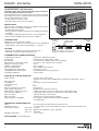
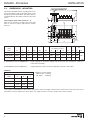
2.2 COMPONENT ASSEMBLY
No. Description
1 Subbase for pneumatic connection of the Buslink valve island
2 AS-Interface bus connection
3 Monostable or bistable 3/2-2x3/2-5/2-5/3 spool valves (max. 8)
4 Operating ports "2-4" with threaded connection or instant fittings (top side ports)
5 Pressure supply "1" and exhausts "3-5" with threaded connections
6 Connecting flange for pressure supply (for island with 8 valves) (see page 11)
7 LED visual indicator for pilot valves
8 AS-Interface; adapter for AS-Interface bus cable (yellow)
9 AS-Interface; adapter for additional AS-Interface power supply cable (black)
10 Island addressing
11
2 LEDs for AS-Interface and supply
8 LEDs for inputs
12 Input connection with female panel connectors ØM12 (upon request)
13 Common exhaust of pilots 82-84 (ØM5)
6
3 4
5
3
1
5
7
1
NTERFACE
ASI
PWR
IN1-1 IN1-2
IN1-3 IN1-4
2
12
8
9
10 11
IN2-1
IN2-2
IN2-3 IN2-4
13

6
BUSLINK - AS-Interface INSTALLATION
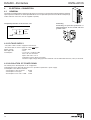
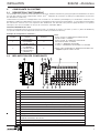
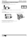
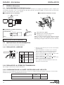
2.3 DIMENSIONS - MOUNTING
The island is provided with four mounting holes in the
spool valve subbase and two mounting holes on the
left side for input/output modules. The centre distance
L2 is dependent on the number and size of the spool
valves.
Total length of spool valve island: L2 + 77
Make sure to provide for enough room on the right
side for pressure supply and optional exhaust
silencers.
B C D ØF K1 K2 4 6 8 P1 P2 (1) (2)
163 23 47.5 4.5 60.4 15 91.5 123.5 155.5 3 35 120
163.5 28.3 59 5.5 60.4 21 105 143 181 3 33 130 190
181.5 34.7 70.5 5.5 60.4 26 126.5 172.5 218.5 3 31 170
Valve
series
569 (M5)
570 (G1/8)
571 (G1/4)
L2
n2: number of valves
(1) BUSLINK AS-Interface without input : height required for pneumatic cabling with rilsan hoses (the AS-Interface cables are
connected horizontally).
(2) BUSLINK AS-Interface with inputs : height required for electric connection with M12 connectors and cables.
Weight of one bus module
- without input : 0.550 kg
- with inputs : 0.600 kg
468
0.9 1.32 1.73
1.14 1.6 2.06
1.18 1.66 2.14
1.61 2.31 3.01
n2: number of valves
Weight of a Buslink island without bus module (kg)
Valve
series
569
570 (3/2)
570 (5/2-5/3)
571
66,5 L2
28,5
B
P3 (1) (2)
C
P2K2
5 5,5
CK1D
4 ØF
2 Ø5,5
P1
n2
NTERFACE
ASI
PWR
IN1-1 IN1-2
IN1-3 IN1-4
IN2-1
IN2-2
IN2-3 IN2-4
WEIGHTS
Total weight of a BUSLINK spool valve island - generation C: define the weight of the pneumatic components from the spool valve series
and number of valves required (see above table) + the weight of the bus connection module (with or without inputs).
mm
P3

7
INSTALLATION BUSLINK - AS-Interface
(1) For detailed information on spool valves see chapter 2.1.
ORDERING EXAMPLE:
Reference : CEBI00A4
CP300Q0G106-KKMMJJ
BUSLINK valve island - Generation C, AS-Interface protocol, with 2 nodes, 8 outputs and 8 inputs over 4 ØM12 connectors.Island for 6 spool
valves series 570 with outputs and instant fitting for flexible hose OD 6 mm,
equipped as follows:
- Positions nos. 1 and 2 : 2 monostable 3/2 spool valves NC, type K
- Positions nos. 3 and 4 : 2 monostable 5/2 spool valves, type M
- Positions nos. 5 and 6 : 2 bistable 5/2 spool valves, type J
NOTE : In this configuration, the bistable spool valves are always to be placed on the right-hand side of the island.
ACCESSORIES (see page 20)
2.4
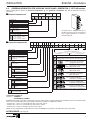
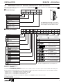
ORDERING INFORMATION FOR A BUSLINK VALVE ISLAND - GENERATION C - WITH AS-Interface
When ordering please specify the electrical compontents (1), the pneumatic components (2), and the optional accessories
separately.
■■
■■
■
Electrical components
1234 5678
No. of
places
-
8
OPTION
GR
P
C
▲
▲
▲
▲
▲
▲
Number of positions : - 4 bistable valves or
- 4 to 8 monostable valves (1)
P Pneumatic components
GR
Spool valve
series and size
▲
2 569 (ØM5 or instant fittings)
3 570 (G1/8 or instant fittings)
4 571 (G1/4)
4
6
OPTIONS
00 without
- -
other options
99
}
G Gaz thread
N NPT thread
Q instant fittings (metric)
Connection
Ports : 2 - 4
Position
0 top side
G Gaz thread
N NPT thread
Connection
Position
Ports: 1 - 3 - 5
1 lateral
04
06
08
Number of spool valve
places
on the island
1
■■
■■
■
Pneumatic components
2
A
A
SI
IN
1-1
IN
1
-2
PW
R
IN
1
-3
IN
1
-4
IN
2-1
I
N
2
-2
IN
2-
3
IN
2
-4
(1)
Generation C
▲
▲
-
▼
▼
▲
OPTION
TYPE
B
I
Generation C
OPTION
00 without option
- -
other options
99
}
▼
C
E
BI BUSLINK-AS-Interface
E Electrical components
▼
A1 1 node - 4 outputs
A2 1 node - 4 outputs / 4 inputs
A3 2 node - 8 outputs
A4 2 node - 8 outputs / 8 inputs
Input/Output number
An island can be equipped with two or
four M12 connectors (A) for connection of
four or eight input/sensors as shown in
the table opposite.
Type
Spool valve functions
Blanking plates for electr./pneum. mounting surface
3/2 NC- Solenoid air operated pilot
Spring/Differential return
2 x -
Solenoid air operated pilot
3/2 NC
Differential return
5/2 - Solenoid air operated pilot
Differential return
5/2 - Solenoid air operated
pilot and return
5/3 - Pressure held (W1)
Solenoid air operated pilot
5/3 - Pressure applied (W2)
Solenoid air operated pilot
5/3 - Exhaust released (W3)
Solenoid air operated pilot
24
3
5
14
12
1
14 1214
2
3
5
4
1
14
12
14
2
3
5
4
1
24
3
5
14
12
1
24
3
5
14
12
1
A
E
B
G
J
M
K
Z
2
3
1

8
BUSLINK - AS-Interface INSTALLATION
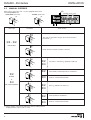
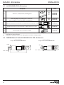
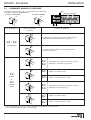
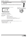
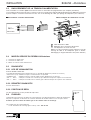
2.5 MANUAL OVERRIDE
Spool valves series 569 - 570 - 571 are equipped with manual
override by impulse (A).
monostable spool valve bistable spool valve
Valve type
Procedure Valve function
3/2 - 5/2
monostable
5/2
bistable
or
5/3
with neutral position
The valve is activated as long as the manual override is
pressed in (
*
)
Reset when the manual override is released
The valve is activated (
*
) (identical to pilot 14)
5/2
5/3
5/2
Permanently activated position is maintained
5/3
Reset to central neutral position
5/2
5/3
5/2
Reset position is maintained
5/3
Reset to central neutral position
(
*
) These changes can only be made if the valve is under pressure.
Supply pressure at port 1 (min. 1.5 bar).
(A)
(A)
42
513
14
12
(A)
Reset (
*
) (identical to return 12)
(bistable spool valve)

9
INSTALLATION BUSLINK - AS-Interface
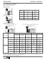
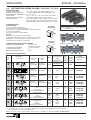
2.6
SPOOL VALVE SERIES 569 (ØM5) - 570 (G1/8) - 571 (G1/4)
The 5/2 spool valves can be used in function 3/2 NC (by plugging port 2) or 3/2 NO (by plugging port 4).
(1) The function of push/pull pilot valves corresponds to the function of conventional valves. Marking to ISO 1219-1.
NOTE - Only one valve size per island.
SPECIFICATIONS
FLUID : air or neutral gas, filtered 30µm, lubricated or not
OPERATING PRESSURE : 1.5 to 8 bar (2.5 to 8 bar series 569 functions 5/3)
ALLOWABLE TEMPERATURE : +5 °C to +50 °C
FUNCTION : 3/2 - 2x3/2 - 5/2 - 5/3, monostable or bistable
OPERATORS : solenoid air operated with internal supply
SPECIAL FEATURE : in the push/pull version both pilots are integrated in
the operator placed on one side = compact solution
(see P586-2).
CONSTRUCTION
SPOOL VALVE
Body in light alloy, cover in thermoplastic (PA-Ar)
Internal parts in stainless steel, light alloy and acetal resin (POM)
Sealings in nitrile (NBR)
PILOT VALVE
Sealings in nitrile (NBR)
Electrical equipment in compliance with standard NF C79300
Coil and iron circuit encapsulated in epoxy resin
Impulse manual override (A)
ELECTRICAL SPECIFICATIONS
VOLTAGE : 24V DC ±10%
max. ripple ratio: 10%
CONSUMPTION : 1.7 W (per coil)
INSULATION CLASS : F
PROTECTION : IP 65
CHOICE OF EQUIPMENT
M5
G1/8
G1/4
569 00 020
570 00 020
571 00 020
M5
G1/8
G1/4
569 00 018
570 00 018
571 00 018
M5
G1/8
G1/4
569 00 016
570 00 016
571 00 016
M5
G1/8
G1/4
569 00 014
570 00 014
571 00 014
M5
G1/8
G1/4
569 00 012
570 00 012
571 00 012
2 (569)
3 (570)
4 (571)
2 (569)
3 (570)
4 (571)
2 (569)
3 (570)
4 (571)
2 (569)
3 (570)
4 (571)
2 (569)
3 (570)
4 (571)
24
3
5
14
12
1
24
3
5
14
12
1
24
3
5
14
12
1
14
12
14
2
3
5
4
1
14 1214
2
3
5
4
1
175
600
1050
175
600
1050
175
600
1050
175
600
1050
175
600
1050
2,5
4
6
2,5
4
6
2,5
4
6
2,5
4
6
2,5
4
6
5/3
5/3
5/3
5/2
5/2
E
B
G
J
M
K
TYPE
(A)
Monostable
spool valve
(A)
Bistable
spool valve
VALVE
CODES
(24 VDC)
Pilot
(14)
Return
(12)
Operators
Solenoid
air
Differential
Solenoid
air
Solenoid
air
GR
Symbols
(1)
Functions
Pressure held
W1
solenoid air
Flow
at 6 bar
(l/min.)
Ø
Ports
2 - 4
Pressure applied
W2
solenoid air
Exhaust released
W3
solenoid air
Ori-
fice
(mm)
2x
3/2
NC
Solenoid
air
Differential
3
(570)
G1/8
550
5
570 00 103
1 = Pressure 12 = Return
2-4 = Operating ports 14 = Pilot
3-5 = Exhausts
570 spool valve (2 x 3/2)
570 spool valve (5/2)
3/2
NC
Solenoid
air
Spring/
Differential
Z
3 (570)
G1/8
Instant fitting for flexible
hose O.D.6 mm
400
5
570 00 053
570 00 051
2
3
1

10
BUSLINK - AS-Interface INSTALLATION
3 ASSEMBLY OF BUSLINK Generation C with AS-Interface
3.1 MOUNTING
Mount the island as described in chapter 2.3.
Make sure to provide for enough room for the cables, connectors and optional exhaust silencers. Proceed with pneumatic and
electrical connection.
A
Pressure supply 1
and exhausts 3 - 5
Operating ports 2 - 4
Bus connection (yellow cable)
24VDC power supply to valves (black cable)
Sensor inputs (upon request)
B
C
D
E
3.2 PNEUMATIC CONNECTION
3.2.1 GENERAL
■■
■■
■ To subbase
569 G 1/8 G 1/8 M 5 M 5 (❇)
570 (3/2-2x3/2) G 1/4 G 1/4 M 5
instant fittings
G1/8
570 (5/2-5/3) G 1/4 G 1/4 M 5 G 1/8 (❇)
571 G 3/8 G 3/8 M 5 G 1/4
Pressure supply
(1)
Exhausts
(3) (5)
Pilot valve exhausts
(82/84)
Operating ports
(2) (4)
Series
(❇) or with connecting flange and instant fittings for flexible hose:
• OD 4 mm (569)
• OD 6 mm (570)
5
3
1
B
5
3
1
A
E
A
S
I
1
I
N
1
1
I
N
2
2
4
V
D
C
1
I
N
3
1
I
N
4
2
I
N
1
2
I
N
2
2
I
N
3
2
I
N
4
C
D
82-84
4
2
4
2
Version with threaded connection Version with instant fitting
The lines for the following common pneumatic signals are collected in the subbase: supply pressure (1), exhausts (3) and (5),
and pilot valve
exhaust. The connecting ports are either on the right side or - in some versions - on the left side of the subbase (see below).
■■
■■
■ To spool valves
Two connection possibilities for operating ports (2 - 4) on top side:
- Threaded connection directly on the spool valve body.
- With instant fittings for flexible hose (for valve series 569 and 570).
■■
■■
■ Connecting instructions
- Remove all protective plastic caps.
- Insert the gasket which generally comes with the ØM5 connectors or banjo-type screw-fittings.
- Screw down the connectors and screw-fittings correctly.
- Screw in the exhaust silencers.
- Connect the pneumatic piping. Gather the tubes in order to have neat and accessible piping.
■ Recommendation for pressure supply connection (see following page)
■ Connections

11
INSTALLATION BUSLINK - AS-Interface
3.2.2 CONNECTION OF PNEUMATIC SUPPLY
■ SUPPLY WITH 1 PRESSURE (P1)
- Island with 4 to 6 spool valves: pressure supply on right side.
569 G1/8
570 G1/4
571 G3/8
Valve
series
Ports
1 - 3 - 5
5
1
P1
3
+
+
NTERFACE
ASI
PWR
IN1-1 IN1-2
IN1-3 IN1-4
IN2-1
IN2-2
IN2-3 IN2-4
A maximum of five spool valves can be operated at the same time without pneumatic malfunction.
- Island with 8 spool valves
The pressure on an island with more than 6 spool valves must be supplied from both sides.
For this purpose, all islands for 8 to 16 spool valves are equipped with a connecting flange.
NTERFACE
ASI
PWR
IN1-1 IN1-2
IN1-3 IN1-4
IN2-1
IN2-2
IN2-3 IN2-4
5
1
1
5
3
P1
3
P1
■ Supply with 2 different pressures (P1 - P2)
Possibility of supplying 1 to 4 spool valves with pressure P2 (consult us).
1
P1
3
5
A
S
I
I
N
1
-
1
I
N
1
-
2
P
W
R
I
N
1
-
3
I
N
1
-
4
I
N
2
-
1
I
N
2
-
2
I
N
2
-
3I
N
2
-
4
■ External pressure supply of pilot valves (consult us)

12
BUSLINK - AS-Interface INSTALLATION
V N.N
GND
4 ELECTRICAL CONNECTION
4.1 GENERAL
The islands are equipped with 2 vampire-type AS-Interface connectors to connect the bus network and power supply (B).
Upon request, the subbases can also be provided with two or four 5-pin female panel connectors M12 for the inputs (A).
Cables and M12 connectors must be supplied separately.
Bobine
Coil
Spule
Grounding for personal protection is
effected directly on the island with the
ground screw.
A
B
ASI
IN
1-1
IN1
-2
P
W
R
IN
1-3
IN
1-4
IN
2-1
IN
2-2
IN
2-3
IN
2-4
Integrated protection circuit for each coil.
Grounding
1
3
5
4.2 VOLTAGE SUPPLY
- The yellow cable is used to supply the AS-Interface.
- The black cable is used to supply the valves and inputs.
Supply voltage : 24 VDC, ±10%
Max. ripple ratio : ±10 %
Consumption : 1.7 per coil, + 0.2 W per LED
max. 5 W / bus electronics
Inputs: total value < 0.5 A
Calculation of power draw (see below).
Check the supply voltage during operation and make sure the admissible tolerance (±10%) is observed.
4.3 CALCULATION OF POWER DRAW
The island's power draw depends on its configuration.
Calculating this power draw will allow the user to provide for optimal 24 V power supply.
Consumption of the different elements:
- Consumption of bus electronics : 40 mA
- Consumption of one input : 9 mA
- Consumption of one valve + LED : 79 mA

13
INSTALLATION BUSLINK - AS-Interface
CONNECTION WITH M12 CONNECTOR
The two following M12 connector types are recommended:
- Straight duo connector (A) for the connection of 2 separate cables (one for each sensor)
- Straight mono connector (B) for the connection of a sensor or cable bundle.
(B) 881 00 330
(A) 881 00 253
4.4 CONNECTION OF INPUTS (inputs upon request)
Connection with detachable M12 connectors with protection to IP65.
Possibility of connecting sensors with 2 or 3 wires
Sensor Sensor Sensor Sensor Sensor
Connectors to be supplied separately:
(A) Straight 5-pin male duo connector
M12, cable feed-throughs of 3 to
5 mm dia. for each cable
code: 881 00 253
(B) Straight 5-pin male mono connector
M12 for 1 cable feed-through of 4 to
6 mm dia.
code : 881 00 330
Pin Name Description
1 24V DC Supply of inputs
2 IN x +1 Input: positive logic x + 1
3 0 V Common ground (sensors with 3 wires)
4 IN x Input: positive logic x
5 PE Protection earth
A
S
I
I
N
1
-
1
I
N
1
-
2
I
N
1
-
3
I
N
1
-
4
I
N
2
-
1
I
N
2
-
2
I
N
2
-
3
I
N
2
-
4
P
W
R
Wiring diagram of inputs
View from screw side of male connector
● Sensors with 2 wires ● Sensors with 3 wires (magnetoresistive example)
1
2
4
3
5
+
-
+
-
IN x+1
IN x
Sensor
x
Sensor
x+1
24V 24V
GND GND
1
2
4
3
5
Sensor x
IN x
IN x+1
Sensor
x+1
24V 24V
NOTE:
The status of the connected sensors can be sampled over the inputs. The inputs have positive logic, they can be operated together
with sensors with pnp outputs. The inputs are "LOW" and must be switched to + 24 V (HIGH) in order to be activated.
Typical input current: 9 mA at 24 VDC.
● Logical status "LOW" : < 8 V ● Logical status "HIGH" : > 14 V
Max. input voltage for external power supply of inputs: 40 V.
When 2-wires sensors are connected, the max. residual current must be < 1 mA.
In "LOW" status, the max. residual current at the input must be < 1 mA.
Input addressing:
x : IN1-1, IN1-3, IN2-1, IN2-3
X + 1 : IN1-2, IN1-4, IN2-2, IN2-4
(see chapter 4.5)
Island provided with
four M12 panel connectors
for 8 inputs
(2 inputs for each connector)
A
S
I
I
N
1
-
1
I
N
1
-
2
I
N
1
-
3
I
N
1
-
4
I
N
2
-
1
I
N
2
-
2
I
N
2
-
3
I
N
2
-
4
P
W
R
Input addressing:
x : IN1-1, IN1-3
X + 1 : IN1-2, IN1-4
(see chapter 4.5)
Island provided with
two M12 panel connectors
for 4 inputs
(2 inputs for each connector)

14
BUSLINK - AS-Interface INSTALLATION
Valve
position
1234
4.5 ADDRESSING
4.5.1 ADDRESSING OF VALVES
Control signals for the valves (see chapter 4.6)
Valve are addressed according to the type of valve used (monostable or bistable valve).
ASI
PWR
IN1-1 IN1-2
IN1-3 IN1-4
IN2-1
IN2-2
IN2-3 IN2-4
V0.0 V0.2 V0.4 V0.6 V1.0 V1.2 V1.4 V1.6
__ _____ _
■ Bistable valves (max. = 4)
Addressing priority is from top to bottom and from left to right.
V0.0 V0.2 V0.4 V0.6
V0.1 V0.3 V0.5 V0.7
■ NOTE: In 2-node configuration it is possible to mix monostable and
bistable valves (max. configuration = 4 monostable valves and 2 bistable
valves). These are always placed as shown opposite.
In this case, the addressing priority is as follows:
V0.0 V0.2 V0.4 V0.6 V1.0 V1.2
__ __
V1.1 V1.3
ASI
PWR
IN1-1 IN1-2
IN1-3 IN1-4
IN2-1
IN2-2
IN2-3 IN2-4
4.5.2 INPUT ADDRESSING
4 monostable
valves
(1st node)
2 bistable valves
(2nd node)
AS-Interface island with inputs
IN1-1
IN1-3
IN1-2
IN1-4
IN2-1
IN2-3
IN2-2
IN2-4
ASI
PWR
IN1-1 IN1-2
IN1-3 IN1-4
IN2-1
IN2-2
IN2-3 IN2-4
1st node
2nd node
Connect 2 sensors (2 inputs) for each M12 connector (see previous page).
1st node 2nd
node
1st node 2nd node
1st node 2nd node
Valve position
12345678
Addressing:
Pilot
signals
Return
signals
Addressing :
Pilot signals (14)
Return signals
(12)
Valve position
123456
Adressing:
■ Monostable valves (max. = 8)
Horizontal addressing:

15
INSTALLATION BUSLINK - AS-Interface
4.5.3 ADDRESSING SUMMARY
■ AS-Interface island with 1 node
4 monostable valves
(Island reference : A1)
+
+
NTERFACE
ASI
PWR
IN1-1 IN1-2
IN1-3 IN1-4
IN2-1
IN2-2
IN2-3 IN2-4
1
2
3
4
4 monostable valves and 4 inputs
(Island reference : A2)
NTERFACE
ASI
PWR
IN1-1 IN1-2
IN1-3 IN1-4
IN2-1
IN2-2
IN2-3 IN2-4
+
+
1
2
3
4
Data bit
Addressing
Valves Inputs
D0
Valve no.1 / 14 Input 1
V0.0 IN1-1
D1
Valve no. 2 / 14 Input 2
V0.2 IN1-2
D2
Valve no. 3 / 14 Input 3
V0.4 IN1-3
D3
Valve no. 4 / 14 Input 4
V0.6 IN1-4
■ AS-Interface island with 2 nodes
8 monostable valves or 4 bistable valves 8 monostable valves or 4 bistable valves and 8 inputs
(Island reference : A3) (Island reference : A4)
Node number Data bit 8 monostable
valves
4 bistable
valves
4 monostable
valves
and
2 bistable valves
4 inputs 8 inputs
Valve addressing Input addressing
Valve 1/14 Valve 1/14 Valve 1/14 Input 1 Input 1
V0.0 V0.0 V0.0 IN1-1 IN1-1
Valve 2/14 Valve 1/12 Valve 2/14 Input 2 Input 2
V0.2 V0.1 V0.2 IN1-2 IN1-2
Valve 3/14 Valve 2/14 Valve 3/14 Input 3 Input 3
V0.4 V0.2 V0.4 IN1-3 IN1-3
Valve 4/14 Valve 2/12 Valve 4/14 Input 4 Input 4
V0.6 V0.3 V0.6 IN1-4 IN1-4
Valve 5/14 Valve 3/14 Valve 5/14
_
Input 5
V1.0 V0.4 V1.0 IN2-1
Valve 6/14 Valve 3/12 Valve 5/12
_
Input 6
V1.2 V0.5 V1.1 IN2-2
Valve 7/14 Valve 4/14 Valve 6/14
_
Input 7
V1.4 V0.6 V1.2 IN2-3
Valve 8/14 Valve 4/12 Valve 6/12
_
Input 8
V1.6 V0.7 V1.3 IN2-4
D0
D1
D2
D3
D0
D1
D2
D3
1
2
+
+
NTERFACE
ASI
PWR
IN1-1 IN1-2
IN1-3 IN1-4
IN2-1
IN2-2
IN2-3 IN2-4
1
2
3
4
5
678
+
+
NTERFACE
ASI
PWR
IN1-1 IN1-2
IN1-3 IN1-4
IN2-1
IN2-2
IN2-3 IN2-4
1
2
3
4
5
6
7
8
Valve X/14 = voltage supply to "pilot" coil 14
(1)
: port 4 under pressure
Valve X/12 = voltage supply to "return" coil 12 : port 2 under pressure
(1)Except for monostable 3/2 valves series 570 where the pilot is 12 (port 2 under pressure). Return by cutting supply voltage to coil
12 (for pilot signals see chapter 4.6 and following pages).

16
BUSLINK - AS-Interface INSTALLATION
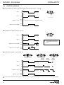
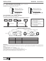
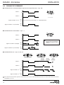
4.6 CONTROL SIGNALS
■ MONOSTABLE 5/2 SPOOL VALVES (differential pneumatic return) - Type: M
■ BISTABLE 5/2 SPOOL VALVE - Type: J
P
0
P
0
24 V
0 V
24 V
0 V
P
0
P
0
24 V
0 V
24 V
0 V
1
1
Port 2
Port 4
Signal to coil 12
not necessary (no coil 12, differential return)
Signal to coil 14 (pilot)
14
12
14
2
3
5
4
1
P = Pressure
These signals can be pulsed
or maintained until change of
status.
1
Port 2
Signal to coil 12 (return)
Port 4
Signal to coil 14 (pilot)
14 1214
2
3
5
4
1
In the 5/3 pressure held version type W1, the pressure at ports 2 and 4 is that which existed when coils 12 and 14 were deenergized.
2
P
0
P
0
24 V
0 V
24 V
0 V
2
2
W2 (B) W3 (E) W1 (G)
Port 2
Signal to coil14
Signal to coil 12
Port 4
■ 5/3 SPOOL VALVES - Types: B - E - G
24
3
5
14
12
1
24
3
5
14
12
1
24
3
5
14
12
1

17
INSTALLATION BUSLINK - AS-Interface
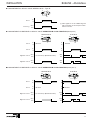
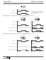
■ MONOSTABLE 3/2 SPOOL VALVE SERIES 570 NC - Type: Z
P
0
24 V
0 V
1
2
3
12
P
0
P
0
24 V
0 V
24 V
0 V
P
0
P
0
24 V
0 V
24 V
0 V
Blocked
Blocked
14
12
14
2
3
5
4
1
14 1214
2
3
5
4
1
BISTABLE
MONOSTABLE
Port 2
Port 4
Signal to coil 14
Signal to coil 12 not necessary (differential return)
■ MONOSTABLE OR BISTABLE 5/2 SPOOL VALVE OPERATED IN 3/2 NO FUNCTION (block port 4)
P
0
P
0
24 V
0 V
24 V
0 V
P
0
P
0
24 V
0 V
24 V
0 V
Blocked
Blocked
14
12
14
2
3
5
4
1
14 1214
2
3
5
4
1
MONOSTABLE
BISTABLE
Port 4
Signal to coil 14
Signal to coil 12
Port 2
■
MONOSTABLE OR BISTABLE 5/2 SPOOL VALVE OPERATED IN 3/2 NC FUNCTION (block port 2)
not necessary (differential return)
Coil 12 (
*
)
Port 2
(
*
) Take signal 14 for the addressing and
pilot connection of the 3/2-spool valves
NC into account.

18
BUSLINK - AS-Interface INSTALLATION
5 AS-INTERFACE NETWORK
5.1 CONNECTION OF AS-Interface BUS
The front panel of the pneumatic spool valve island for AS-Interface is equipped with vampire-type panel connectors for instant
connection. The yellow flat profiled AS-Interface bus cable is screwless and unstripped. It is used to transmit control signals and
supply the sensor inputs.
■■
■■
■ AS-Interface connection to island
+
_
AS-Interface
C
brown
blue
Master
C
X
C
Yellow AS-Interface cable
X
Adapter for AS-Interface connector
This adapter is supplied with the island.
NOTE: When connecting the cable to the island, please
observe the mounting direction of the cable and adapter
(mounting direction of adapter secured by differently sized
side pieces).
NOTE - Carry out all programming instructions prior
to connecting the black power supply cable.
5.2 PROGRAMMING INSTRUCTIONS
See AS-Interface manufacturer's manual.
5.2.1 ADDRESS SELECTION
NTERFACE
ASI
PWR
IN1-1 IN1-2
IN1-3 IN1-4
IN2-1
IN2-2
IN2-3 IN2-4
1
2
3
5.2.2 SETTING OF THE TRANSMISSION SPEED
The transmission speed is fixed and preset by the AS-Interface master.
5.2.3 CONTROLLER CARD CONFIGURATION WITH THE ISLANDS
In case the AS-Interface network is configured with the AS-Interface coupler which is integrated in the PLC, the identification codes
for a JOUCOMATIC AS-Interface island are as follows:
Code
inputs/outputs
ID code
Identificator code of JOUCOMATIC island 7 F
Switch
position
Node
number
1
Addressing
node 1
2
Addressing
node 2
1+2 RUN
■■
■■
■ Connection to AS-Interface master
■■
■■
■ Connection of the AS-Interface bus
AS-
Interface
PC
24V =
AS-
Interface
master
Bridge
1
2
3
1
2
3
1
2
3
1 -
Unscrew the threaded plug to access the addressing
switch.
2 - Set the switch into position 1 and connect the island
to the master or the hand-held programmer.
3 - Program the address for the 1st node, or
increment
or decrement with the hand-held programmer and
press "write".
4 - Set the switch into position 3.
5 - Set the address for the 2nd node, or
increment or
decrement with the hand-held programmer and press
"write".
6 - Set the switch into position 2.
7 - The 2 addresses are saved in the island memory.
Remount the threaded plug.

19
INSTALLATION BUSLINK - AS-Interface
5.3 CONNECTION OF SUPPLY VOLTAGE
The supply voltage is connected after having carried out all programming instructions (see preceding chapters).
The operating voltage is connected to the front of the island with the black profiled AS-Interface cable and the vampire-type
connector provided for instant connection of the cable to the island with a clip-on adapter (see below). No screw or stripping of
cable ends is required).
D
Black AS-Interface cable
X
Adapter for AS-Interface connector
This adapter is supplied with the island.
NOTE: When connecting the cable to the island, please
observe the mounting direction of the cable and adapter
(mounting direction of adapter secured by differently sized
side pieces).
■■
■■
■ Connection to supply unit ■ Connection of supply voltage to island
D
X
C
+
_
24V =
D
brown
blue
Power supply
5.4 STARTUP OF AS-Interface NETWORK
1 - Connect the yellow cable.
2 - Connect the black cable.
3 - Power-on the AS-Interface master.
5.5 DIAGNOSTICS
5.5.1 LED INDICATIONS
ON THE BUSLINK MODULE:
The Buslink AS-Interface module is provided with 2, 6 or 10 diagnostic LEDS (according to the version).
• AS-Interface (green) lights up as soon as data exchange is possible.
• POWER (green) lights up to indicate correct 24 V power supply through the black cable to the valves.
• IN1-1 .... IN1-4 4 LEDs (1-node island with 4 inputs) light up as soon as the sensors are activated.
• IN1-1 .... IN2-4 8 LEDs (2-node island with 8 inputs) light up as soon as the sensors are activated.
5.5.2 DIAGNOSTICS REGISTER
See AS-Interface information.
5.5.3 RESET POSITION
AS-Interface islands are provided with a reset into zero position.
5.6 FUSES
The power supply by the black cable is protected with a fuse enclosed in the bus module housing.
Replace the fuse by unscrewing the lid of the module housing. Remove the fuse with a thin pair of tweezers.
Only fuses of the same type and value may be used for replacement.
(A) Fuse type: 20 mm × 5 mm - 250V/2A
(A)

20
BUSLINK - AS-Interface INSTALLATION
5.8 DIMENSIONS OF THE ACCESSORIES FOR THE AS-Interface
5.7 ACCESSORIES FOR AS-Interface
881 66 905
881 67 001
881 67 101
881 35 525
881 35 532
881 00 253
881 00 330
881 00 302
(3)
569
570
571
569
570
Valve
series
Description
Codes
+
INPUTS (ØM12)
Straight mono connector: 881 00 330
INPUTS (ØM12)
Straight duo connector: 881 00 253
63
M12
Ø 20
M12
Ø 20
60
Ø 3 - 5 mm
PG11
Ø 4 - 6 mm
PG7
(1) (2) These plates can be adapted to islands to block the electrical and pneumatic mounting surfaces of an unused valve place
(removable for further extension).
(3) Length to be specified in metres: max. 100 m (please consult us for longer cables).
A Electrical
(1)
and pneumatic
(2)
blanking plates
Connecting flange for operating ports 2 and 4 with
pressure indicators and instant fittings for flexible hose
Straight 5-pin male duo connector M12 for 2 inputs/outputs (2 cables Ø3 - 5 mm)
Straight 5-pin male mono connector M12 (1 cable Ø 4-6 mm) for 1 input
D Black profiled cable for 24V power supply
La page est en cours de chargement...
La page est en cours de chargement...
La page est en cours de chargement...
La page est en cours de chargement...
La page est en cours de chargement...
La page est en cours de chargement...
La page est en cours de chargement...
La page est en cours de chargement...
La page est en cours de chargement...
La page est en cours de chargement...
La page est en cours de chargement...
La page est en cours de chargement...
La page est en cours de chargement...
La page est en cours de chargement...
La page est en cours de chargement...
La page est en cours de chargement...
La page est en cours de chargement...
La page est en cours de chargement...
La page est en cours de chargement...
La page est en cours de chargement...
-
 1
1
-
 2
2
-
 3
3
-
 4
4
-
 5
5
-
 6
6
-
 7
7
-
 8
8
-
 9
9
-
 10
10
-
 11
11
-
 12
12
-
 13
13
-
 14
14
-
 15
15
-
 16
16
-
 17
17
-
 18
18
-
 19
19
-
 20
20
-
 21
21
-
 22
22
-
 23
23
-
 24
24
-
 25
25
-
 26
26
-
 27
27
-
 28
28
-
 29
29
-
 30
30
-
 31
31
-
 32
32
-
 33
33
-
 34
34
-
 35
35
-
 36
36
-
 37
37
-
 38
38
-
 39
39
-
 40
40


Asco Series 569 570 571 BUSLINK Generation C Le manuel du propriétaire
- Taper
- Le manuel du propriétaire
dans d''autres langues
Documents connexes
-
Asco Series 881 Connectors for Asinterface Connections Le manuel du propriétaire
-
-
-
-
-
-
-
-
-