Asco Series 641 642 669 670 671 BUSLINK Interface Dis Le manuel du propriétaire
- Taper
- Le manuel du propriétaire

DEMONTAGE
1- Démonter le couvercle supérieur en des-
serrant les 6 vis (rep. 6)
2- Desserrer la vis de terre
*
(rep.7)
3- Retirer le (ou les) connecteur(s) nappe
-
connecteur nappe pour distributeur (rep.8)
- connecteur nappe pour module
d'entrée/sortie (rep.9) si présent
4- Retirer l'interface réseau
REMONTAGE
1- Brancher le (ou les) connecteur(s) nappe
(rep.8-9) sur l'interface réseau
2-
Glisser l'interface réseau dans la rainure (rep. A)
3- Visser les cosses de terre
*
(rep.7)
4- Remonter le couvercle et serrer les 6 vis
*
Sur les versions avant date, la vis de terre
se trouve fixée sur le fond arrière du
module. Il faut alors dévisser le couvercle
du fond pour y accéder.
Pour la connexion électrique voir :
- MS-P586-3 (BUSLINK - Génération C)
- MS-P588-3 (BUSLINK - VDMA)
- MS-P589-3 (BUSLINK - ISO)
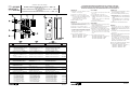
PROCEDURE DE DEMONTAGE-REMONTAGE DE L'INTERFACE BUSLINK
PROCEDURE FOR BUSLINK INTERFACE DISASSEMBLY AND REASSEMBLY
ANLEITUNG ZUR MONTAGE UND DEMONTAGE DES BUSLINK-INTERFACE
PR-P586-1
DISASSEMBLY
1 - Loosen the 6 screws (ref. 6) to remove the
top cover.
2 -Loosen the earth screw * (ref. 7).
3 -Unplug the ribbon cable connector(s):
- Ribbon cable connector for spool valve
(ref. 8)
- Ribbon cable connector for I/O module
(ref. 9) (if existing)
4 -Remove the network interface.
REASSEMBLY
1 - Plug the ribbon cable connector(s) (ref. 8-9)
into the network interface.
2 -
Slide the network interface into the slot (ref. A).
3 -Screw tight the ground lug * (ref.7).
4 -Mount the cover and tighten the 6 screws.
*
On versions of older generations the earth
screw is on the back of the module. Uns-
crew the back cover to access the earth
screw.
For the electrical connection see:
- MS-P586-3 (BUSLINK - Generation C)
- MS-P588-3 (BUSLINK - VDMA)
- MS-P589-3 (BUSLINK - ISO)
DEMONTAGE
1 - Lösen Sie die 6 Schrauben (Nr. 6), um die
obere Abdeckung zu entfernen.
2 -Lösen Sie die Erdungsschraube
* (Nr. 7).
3 - Ziehen Sie den bzw. die Flachbandkabel-
stecker heraus:
- Flachbandkabelstecker für Magnetventil
(Nr. 8).
- Flachbandkabelstecker für Eingangs-/
Ausgangs-Modul (Nr. 9) sofern vorhan-
den.
4 -Entfernen Sie das Netzwerk-Interface.
MONTAGE
1 -Stecken Sie den bzw. die Flachband-
kabelstecker (Nr. 8-9) in das Netzwerk-
Interface.
2 - Schieben Sie das Netzwerk-Interface in die
Rille (Nr. A).
3 - Schrauben Sie den Erdungs-Kabelschuh
fest
* (Nr. 7).
4 -Montieren Sie die Abdeckung und ziehen
Sie die 6 Schrauben an.
*
Bei den Ausführungen der älteren Genera-
tion befindet sich die Erdungsschraube
hinten am Modul. Um an die Erdungs-
schraube zu gelangen, muss die hintere
Abdeckung abgeschraubt werden.
Hinweise zum elektrischen Anschluss finden
Sie in den folgenden Druckschriften:
- MS-P586-3 (BUSLINK - Generation C)
- MS-P588-3 (BUSLINK - VDMA)
- MS-P589-3 (BUSLINK - ISO)
DE
GB
FR
Sachets de pièces de rechange
INTERFACE POUR ILOTS BUSLINK Génération C - VDMA - ISO
Spare parts kits for
INTERFACE FOR BUSLINK SPOOL VALVE ISLANDS Generation C – VDMA - ISO
Ersatzteilliste
INTERFACE FÜR BUSLINK-VENTILINSELN Generation C – VDMA - ISO
Series
Baureihe
641-642
669-670-671
Type/Typ: BUSLINK
(383 45 36)
PR-P586-1
Rep.
DESIGNATION du sachet DESIGNATION of kit
BEZEICHNUNG
der Ersatzteilpackung
CODE
1-4
5
978 02 137
978 02 406
1
2
3
4
5
- Connection M12 + écrou Pp9
- Connecteur d'alimentation 24V - M18
- Obturateur fileté plastique + joint
- Couvercle + joint + étiquette
- Carte interface PROFIBUS-DP
Nomenclature semblable à ci-dessus
adaptée à INTERBUS-S
- Carte interface INTERBUS-S avec
option 25
-
Carte interface INTERBUS-S avec option 13
Interface pour protocole PROFIBUS-DP
Interface pour protocole INTERBUS-S
2
4
1
3
5
8
7
9
1-4
5
978 02 139
Nomenclature semblable à ci-dessus
adaptée à DEVICE-NET y compris
la carte interface DEVICE-NET
Interface pour protocole DEVICE-NET
1-4
5
978 02 140
Nomenclature semblable à ci-dessus
adaptée à FIPIO y compris
la carte interface FIPIO
Interface pour protocole FIPIO
1-4
5
978 02 141
Nomenclature semblable à ci-dessus
adaptée à MODBUS y compris
la carte interface MODBUS
Interface pour protocole MODBUS
+5V
+24V
RUN
COM
I/O
ERR
Pg21
6
7
A
- M12 connection + Pp9 nut
- 24 V power supply connector - M18
- Threaded plastic plug + seal
- Cover + seal + label
- Profibus-DP interface card
Same description as above adapted to
INTERBUS-S
- INTERBUS-S interface card with option 25
.
-
INTERBUS-S interface card with option 13
Interface for PROFIBUS-DP protocol
Interface for INTERBUS-S protocol
Same description as above adapted to
DEVICE-NET
- DEVICE-NET interface card
Interface for DEVICE-NET protocol
Same description as above adapted to
FIPIO
- FIPIO interface card
Interface for FIPIO protocol
Same description as above adapted to
MODBUS
- MODBUS interface card
Interface for MODBUS protocol
- M12-Anschluss + Pp9 Mutter
- 24V-Spannungsversorgungsstecker - M18
- Kunststoffstopfen mit Außengewinde + Dichtung
- Abdeckung + Dichtung – Etikett
- PROFIBUS-DP-Interface-Karte
Teilebezeichnung wie oben auf
INTERBUS-S abgestimmt.
- INTERBUS-S-Interface-Karte mit optie 25
.
- INTERBUS-S-Interface-Karte mit optie 13
Interface für PROFIBUS-DP-Protokoll
Interface für INTERBUS-S-Protokoll
Teilebezeichnung wie oben auf
DEVICE-NET abgestimmt.
- DEVICE-NET-Interface-Karte
Interface für DEVICE-NET-Protokoll
Teilebezeichnung wie oben auf FIPIO
abgestimmt
- FIPIO-Interface-Karte
Interface für FIPIO-Protokoll
Teilebezeichnung wie oben auf
MODBUS abgestimmt
- MODBUS-Interface-Karte
Interface für MODBUS-Protokoll
1-4
5
978 02 423
Nomenclature semblable à ci-dessus
adaptée à ASinterface y compris :
- Carte interface ASinterface
avec 1 noeud sans entrée
- Carte interface ASinterface
avec 2 noeuds sans entrée
- Carte interface ASinterface
avec 1 noeud avec entrées
- Carte interface ASinterface
avec 2 noeuds avec entrées
Interface pour protocole ASinterface
Same description as above adapted to
ASinterface
- ASinterface interface card
with 1 node without input
- ASinterface interface card
with 2 nodes without input
- ASinterface interface card
with 1 node with inputs
- ASinterface interface card
with 2 nodes with inputs
Interface for ASinterface protocol
Teilebezeichnung wie oben auf
ASinterface abgestimmt
- ASinterface-Interface-Karte
mit 1 Konten Ohne Eingänge
- ASinterface-Interface-Karte
mit 2 Konten Ohne Eingänge
- ASinterface-Interface-Karte
mit 1 Konten mit Eingängen
- ASinterface-Interface-Karte
mit 2 Konten mit Eingängen
Interface für ASinterface-Protokoll
978 02 424
978 02 425
978 02 426
978 02 504
-
 1
1

Asco Series 641 642 669 670 671 BUSLINK Interface Dis Le manuel du propriétaire
- Taper
- Le manuel du propriétaire
dans d''autres langues
Documents connexes
-
Asco Series 569 570 571 BUSLINK Generation C Le manuel du propriétaire
-
-
-