Craftsman 55 lb. Tractor Wheel Weight Le manuel du propriétaire
- Taper
- Le manuel du propriétaire

PRINTED IN USA FORM NO. 42567 (06/25/12)
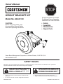
WEIGHT BRACKET KIT
Model No. 486.24100
Owner's Manual
®
STOP
DO NOT RETURN TO STORE
For Missing Parts or Assembly
Questions Call 1-866-576-8388
CAUTION:
Before using this product, read
this manual and follow all Safety
Rules and Operating Instructions.
Sears Brand Management Corporation, Hoffman Estates, IL 60179 U.S.A.
www.craftsman.com
• Safety
• Assembly
• Maintenance
• Repair Parts
SAFETY RULES
Remember, any power equipment can cause injury if operated improperly or if the user does not understand how to operate the
equipment. Exercise caution at all times when using power equipment.
LOOK FOR THIS SYMBOL TO POINT OUT
IMPORTANT SAFETY PRECAUTIONS. IT
MEANS — ATTENTION! BECOME ALERT!
YOUR SAFETY IS INVOLVED.
VEHICLE BRAKING AND STABILITY MAY
BE AFFECTED WITH THE ADDITION OF AN
ACCESSORY OR AN ATTACHMENT. BE AWARE
OF CHANGING CONDITIONS ON SLOPES.
• Refer to your tractor owners manual for "Rules For Safe
Operation."
• Do not use more than one 55 lb. weight with this bracket.
• Use 55 lb. weight for snow removal or tilling only.
• Weight must be removed when mower deck is installed.

2
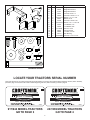
Look under the seat of your tractor and locate the model number. For tractors with model numbers beginning with 917 (944 in Canada),
proceed to page 3. For tractors with model numbers beginning with 247 (459 in Canada), proceed to page 4.
193653
®
MODEL
917. 000000
SERIAL
000000A000000
193653
®
MODEL
247. 000000
SERIAL
000000A000000
917/944 MODEL TRACTORS
GO TO PAGE 3
247/459 MODEL TRACTORS
GO TO PAGE 4
CARTON CONTENTS
HARDWARE PACKAGE
REF QTY PART NO DESCRIPTION
1 1 24215 Weight Bracket
2a 2 26553 Weight Bracket Arm
2b 2 27347 Weight Bracket Arm
3 6 43001 Hex Bolt, 3/8-16 x 1"
4 2 43840 Hex Bolt, 5/16-18 x 1-1/4"
5 2 R19171616 Washer, .1/2" x 1" O.D.
6 2 43081 Washer, 5/16"
7 4 47630 Hex Bolt, 5/16-18 x 3/4"
8 2 R19172410 Washer, 1/2" x 1-1/2" O.D.
9 2 43353 Lock Washer, 1/2"
10 6 43003 Lock Washer, 3/8"
11 2 712-0206 Nex Nut, 1/2-13
12 6 43015 Hex Nut, 3/8-16
13 2 43064 Lock Nut, 5/16-18
14 2 1657-5 Step Bushing
15 2 R74760884 Hex Bolt, 1/2-13 x 5-1/2"
1
2a
2a
2b 2b
3 4
5
6
8
9
10
15
12
13
14
11
7
LOCATE YOUR TRACTORS SERIAL NUMBER

3
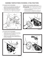
FIGURE 1
FIGURE 2
IF YOU HAVE THIS STYLE DRAWBAR:
1. Assemble two 1.5" O.D. washers (8) onto two 3/8-16 x 1" hex
bolts (3). Insert bolts through drawbar and assemble weight
bracket (1) onto bolts. Fasten securely with two 3/8" lock
washers(10)andtwo3/8-16hexnuts(12).Seegure1.
2. Assemble wheel weight to weight bracket (1) using two 1/2" x
5-1/2" hex bolts (15), 1" O.D. washers (5), 1/2" lock washers
(9)and1/2-13hexnuts(11).Tightensecurely.Seegure1.
10
15
9
11
DRILL 13/32"
HOLE ON
OLDER
TRACTORS
5
3
8
12
ASSEMBLY INSTRUCTIONS FOR MODEL 917/944 TRACTORS
FIGURE 3B
12
10
3
5
5
P
O
U
N
D
S
9
11
15
5
Use these two holes
5
5
P
O
U
N
D
S
9
11
15
5
12
10
3
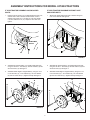
FIGURE 3A
Usegure3Aformosttractorswiththisstyle
drawbar.Usegure3Biftheweightbracketinterferes
withthegastank.
5. Assemble weight bracket (1) to weight bracket arms (2a) using
four 3/8-16 x 1" hex bolts (3), 3/8" lock washers (10) and 3/8-
16hexnuts(12).Seegure3.
6. Assemble wheel weight to weight bracket (1) using two 1/2" x
5-1/2" hex bolts (15), 1" O.D. washers (5), 1/2" lock washers
(9)and1/2-13hexnuts(11).Tightensecurely.Seegure3.
12
10
3
14
4
6
13
IF YOU HAVE THIS STYLE DRAWBAR:
3. Assemble bottom of two weight bracket arms (2a) to sides of
drawbar using two 3/8-16 x 1" hex bolts (3), 3/8" lock washers
(10)and3/8-16hexnuts(12).Seegure2.
4. Assemble top of two weight bracket arms (2a) to sides of
drawbar using front notches in arms. Use two 5/16-18 x 1-1/4"
hex bolts (4), step bushings (14), 5/16" washers (6) and 5/16"
locknuts(13).Seegure2.

4
FIGURE 4
ASSEMBLY INSTRUCTIONS FOR MODEL 247/459 TRACTORS
1. Place the second notch in top of weight bracket arm (2a) onto
shoulder bolt in side of drawbar. Secure bottom of arm to
drawbar using a 3/8-16 x 1" hex bolt (3), a 3/8" lock washer
(10) and a 3/8-16 hex nut (12). Repeat on other side. See
gure4.
1. Attach both weight bracket arms (2b) to drawbar using four
5/16"x3/4"hexbolts.Seegure6.
12
10
3
SHOULDER
BOLTS
12
10
3
5
5
P
O
U
N
D
S
9
11
15
5
2. Assemble the weight bracket (1) to weight bracket arms (2a)
using four 3/8-16 x 1" hex bolts (3), 3/8" lock washers (10) and
3/8-16hexnuts(12).Seegure4.
3. Assemble wheel weight to weight bracket (1) using two 1/2" x
5-1/2" hex bolts (15), 1" O.D. washers (5), 1/2" lock washers
(9)and1/2-13hexnuts(11).Tightensecurely.Seegure4.
2. Assemble the weight bracket (1) to weight bracket arms (2b)
using four 3/8-16 x 1" hex bolts (3), 3/8" lock washers (10) and
3/8-16hexnuts(12).Seegure4.
3. Assemble wheel weight to weight bracket (1) using two 1/2" x
5-1/2" hex bolts (15), 1" O.D. washers (5), 1/2" lock washers
(9)and1/2-13hexnuts(11).Tightensecurely.Seegure7.
FIGURE 5
FIGURE 6
FIGURE 7
7
11
12
9
10
3
15
5
IF YOUR TRACTOR DRAWBAR HAS SHOULDER
BOLTS:
IF YOUR TRACTOR DRAWBAR DOES NOT HAVE
SHOULDER BOLTS:

5
• Sécurité
• Assemblage
• Entretien
• Piècesderechange
CONSIGNES DE SÉCURITÉ
Tout appareil mécanique ou motorisé risque de provoquer des blessures si ce dernier n'est pas utilisé correctement ou si l'utilisateur ne
sait pas comment l'utiliser. Faites preuve de prudence à tout moment lorsque vous utilisez un appareil mécanique ou motorisé.
CE SYMBOLE INDIQUE DES CONSIGNES
DE SÉCURITÉ IMPORTANTES. IL SIGNIFIE:
ATTENTION ! SOYEZ VIGILANT ! VOTRE
SÉCURITÉ EN DÉPEND!
ATTENTION : LE FREINAGE ET LA
STABILITÉ DU VÉHICULE RISQUENT D’ÊTRE
MODIFIÉS PAR L’AJOUT D’UN ACCESSOIRE.
AYEZ CONSCIENCE DES CONDITIONS
CHANGEANTES SUR LES PENTES.
• Consultez les « Règles d'utilisation sécuritaires » du
manuel d’utilisation de votre tracteur.
• N’utilisez pas plus d’un contrepoids de 25 kg (55 lb) avec
ce support.
• N’utilisez le contrepoids de 25 kg (55 lb) que pour le
déneigement ou le labourage.
• Le contrepoids doit obligatoirement être déposé lors de
l’installation du capot de la tondeuse.
PRINTED IN USA FORM NO. 42567 (06/25/12)
JEU DE SUPPORT POUR CONTREPOIDS
Modèle N° : 486.24100
Manueldupropriétaire
®
ATTENTION:
Lire et suivre attentivement les
instructions et consignes de sécurité de
ce manuel avant d'utiliser cet article.
Sears Brand Management Corporation, Hoffman Estates, IL 60179 É.-U.
www.craftsman.com

6
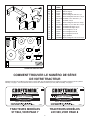
Identiezlenumérodemodèledevotretracteur,souslaselle.Pourlestracteursdontlenumérodemodèlecommencepar917(944au
Canada), voir page 7. Pour les tracteurs dont le numéro de modèle commence par 247 (459 au Canada), voir page 8.
193653
®
MODEL
917. 000000
SERIAL
000000A000000
193653
®
MODEL
247. 000000
SERIAL
000000A000000
TRACTEURS MODÈLES
917/944, VOIR PAGE 7
TRACTEURS MODÈLES
247/459, VOIR PAGE 8
CONTENU DU CARTON
SACHET DE QUINCAILLERIE
RÉF. QTÉ Nº DE
PIÈCE
DESCRIPTION
1 1 24215 Support de contrepoids
2a 2 26553 Bras du support
2b 2 27347 Bras du support
3 6 43001 Boulon hexagonal, 3/8-16 x 1 po
4 2 43840 Boulon hexagonal, 5/16-18 x 1-1/4 po
5 2 R19171616 Rondelle, 0,12 x diam. ext. 1 po
6 2 43081 Rondelle, 5/16 po
7 4 47630 Boulon hexagonal, 5/16-18 x 3/4 po
8 2 R19172410 Rondelle, 1/2 po x diam. ext. 1-1/2 po
9 2 43353 Rondelle de blocage, 1/2 po
10 6 43003 Rondelle de blocage, 3/8 po
11 2 712-0206 Écrou hexagonal, 1/2-13
12 6 43015 Écrou hexagonal, 3/8-16
13 2 43064 Écrou hexagonal, 5/16-18
14 2 1657-5 Bague épaulée
15 2 R74760884 Boulon hexagonal, 1/2-13 x 5-1/2 po
1
2a
2a
2b 2b
3 4
5
6
8
9
10
15
12
13
14
11
7
COMMENT TROUVER LE NUMÉRO DE SÉRIE
DE VOTRE TRACTEUR

7
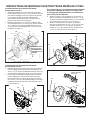
FIGURE 1
FIGURE 2
SI VOTRE TRACTEUR EST ÉQUIPÉ D’UNE BARRE
D’ATTELAGE DE CE TYPE :
1. Mettez deux rondelles de 1,5 po de diam. ext. (8) sur deux
boulons hexagonaux de 3/8-16 x 1 po (3). Passez ces boulons
dans la barre d’attelage et montez le support de contrepoids
(1) sur celles-ci. Bloquez l’ensemble solidement avec
deux rondelles de blocage de 3/8 po (10) et deux écrous
hexagonauxde3/8-16(12).Voirlagure1.
2. Montez le contrepoids sur son support (1) à l’aide de deux
boulons hexagonaux de 1/2 x 5-1/2 po (15), de deux rondelles
de 1 po diam. ext. (5), de deux rondelles de blocage de 1/2
po (9) et de deux écrous hexagonaux de 1/2-13 (11). Serrez
fermement.Voirlagure1.
INSTRUCTIONS DE MONTAGE POUR TRACTEURS MODÈLES 917/944
FIGURE 3B
5
5
P
O
U
N
D
S
9
11
15
5
12
10
3
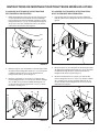
FIGURE 3A
Voirlagure3Apourlaplupartdestracteurséquipés
d’unebarred’attelagedecetype.Voirlagure3B
silesupportducontrepoidscauseuneinterférence
avecleréservoirdecarburant.
5. Montez le support (1) de contrepoids sur ses bras (2a) à
l’aide de quatre boulons hexagonaux de 3/8-16 x 1 po (3),
de quatre rondelles de blocage de 3/8 po (10) et de quatre
écroushexagonauxde3/8-16(12).Voirlagure3.
6. Montez le contrepoids sur son support (1) à l’aide de
deux boulons hexagonaux de 1/2 x 5-1/2 po (15), de deux
rondelles de diam. ext. 1 po (5), de deux rondelles de
blocage de 1/2 po (9) et de deux écrous hexagonaux de
1/2-13(11).Serrezfermement.Voirlagure3.
12
10
3
14
4
6
13
SI VOTRE TRACTEUR EST ÉQUIPÉ D’UNE BARRE
D’ATTELAGE DE CE TYPE :
3. Montez le bas des deux bras du support (2a) sur les côtés de
la barre d’attelage à l’aide de deux boulons hexagonaux de
3/8-16 x 1 po (3), de deux rondelles de blocage de 3/8 po (10)
etdedeuxécroushexagonauxde3/8-16(12).Voirlagure2.
4. Fixez le haut des deux bras des supports (2a) aux côtés de
la barre d’attelage, en vous servant des deux encoches à
l’avant des bras. Fixez à l’aide de deux boulons hexagonaux
de 5/16-18 x 1-1/4 po (4), des bagues épaulées (14), de deux
rondelles de 5/16 po (4) et de deux contre-écrous de 5/16 po
(13).Voirlagure2.
10
15
9
11
PERCEZ UN TROU
DE 13/32 po SUR
LES MODÈLES DE
TRACTEURS PLUS
ANCIENS
5
3
8
12
12
10
3
5
5
P
O
U
N
D
S
9
11
15
5
Vissez dans ces
deux trous

8
FIGURE 4
INSTRUCTIONS DE MONTAGE POUR TRACTEURS MODÈLES 247/459
1. Mettez la deuxième encoche en haut du bras du support (2a)
sur la vis épaulée de la paroi latérale de la barre d’attelage.
Fixez le bas du bras à la barre d’attelage à l’aide d’un boulon
hexagonal de 3/8-16 x 1 po (3), d’une rondelle de blocage de
3/8 po (10) et d’un écrou hexagonal de 3/8-16 (12). Faites la
mêmechosedel’autrecôté.Voirlagure4.
1. Fixez les deux bras du support (2b) à la barre d’attelage à
l’aide de quatre boulons hexagonaux de 5/16 x 3/4 po. Voir la
gure6.
12
10
3
VIS
ÉPAULÉE
12
10
3
5
5
P
O
U
N
D
S
9
11
15
5
2. Montez le support (1) de contrepoids sur ses bras (2a) à l’aide
de quatre boulons hexagonaux de 3/8-16 x 1 po (3), de quatre
rondelles de blocage de 3/8 po (10) et de quatre écrous
hexagonauxde3/8-16(12).Voirlagure4.
3. Montez le contrepoids sur son support (1) à l’aide de deux
boulons hexagonaux de 1/2 x 5-1/2 po (15), de deux rondelles
de 1 po diam. ext. (5), de deux rondelles de blocage de 1/2
po (9) et de deux écrous hexagonaux de 1/2-13 (11). Serrez
fermement.Voirlagure4.
2. Montez le support (1) de contrepoids sur ses bras (2b) à l’aide
de quatre boulons hexagonaux de 3/8-16 x 1 po (3), de quatre
rondelles de blocage de 3/8 po (10) et de quatre écrous
hexagonauxde3/8-16(12).Voirlagure4.
3. Montez le contrepoids sur son support (1) à l’aide de deux
boulons hexagonaux de 1/2 x 5-1/2 po (15), de deux rondelles
de 1 po diam. ext. (5), de deux rondelles de blocage de 1/2
po (9) et de deux écrous hexagonaux de 1/2-13 (11). Serrez
fermement.Voirlagure7.
FIGURE 5
FIGURE 6
FIGURE 7
7
11
12
9
10
3
15
5
SI LA BARRE D’ATTELAGE DE VOTRE TRACTEUR
EST ÉQUIPÉE DE VIS ÉPAULÉES :
SI LA BARRE D’ATTELAGE DE VOTRE TRACTEUR
N’EST PAS ÉQUIPÉE DE VIS ÉPAULÉES :
-
 1
1
-
 2
2
-
 3
3
-
 4
4
-
 5
5
-
 6
6
-
 7
7
-
 8
8


