
ENGLISH A-1
ENGLISHFRANÇAISESPAÑOL
©2018 Honda Motor Co., Ltd. –All Rights Reserved
GX25NT · GX35NT · GX50NT
GX25T · GX35T · GX50T
37Z3V600
00X37-Z3V-6000
OWNER’S MANUAL
GX25 • GX35 • GX50
The engine exhaust from this product contains
chemicals known to the State of California to cause
cancer, birth defects, or other reproductive harm.
The illustrations in this manual are based on the GX50.
• The illustrations may vary according to the type.
SAFETY LABEL LOCATION / COMPONENT & CONTROL LOCATION
WARNING LABEL For EU Except EU
attached to
product
supplied with
product
supplied with
product
attached to
product
supplied with
product
supplied with
product
This label warns you of potential hazards that can cause
serious injury. Read it carefully.
If the label comes off or becomes hard to read, contact
your servicing dealer for replacement.
Gasoline is highly flammable and explosive.
Stop the engine and let cool before
refueling.
The engine emits toxic poisonous
carbon monoxide gas. Do not run in
an enclosed area.
Read Owner’s Manual before
operation.
OIL FILLER CAP/
DIPSTICK
WARNING LABEL
AIR CLEANER
PRIMING PUMP
FUEL FILLER CAP
SPARK PLUG
(inside the top cover)
TOP COVER
MUFFLER
(inside the top cover)
STARTER GRIP
OIL FILLER CAP/
DIPSTICK
RECOIL STARTER
FUEL TANK
TANK GUARD
(applicable type)
ENGINE CONTROLS
CHOKE LEVER
THROTTLE LEVER
GX25/GX35: applicable types
THROTTLE LEVER
ENGINE SWITCH
37Z3V6000.book Page 1 Friday, June 8, 2018 10:35 AM

A-2
Figure/Figura 1
[1]
[B]
[A]
[2]
[A]
[B]
[A]
[B]
[3]
[4]
[5]
[6]
[7]
[A]
[B]
[A]
[B]
[A]
[B]
[A]
[B]
Figure/Figura 2
[1]
MAXIMUM FUEL LEVEL
NIVEAU DE CARBURANT MAXIMUM
NIVEL MÁXIMO DE COMBUSTIBLE
Figure/Figura 3
AMBIENT TEMPERATURE
TEMPERATURE AMBIANTE
TEMPERATURA AMBIENTE
Figure/Figura 4
UPPER LIMIT
LIMITE SUPERIEURE
LÍMITE SUPERIOR
LOWER LIMIT
LIMITE INFERIEURE
LÍMITE INFERIOR
[2]
[1]
Figure/Figura 5
[2]
[1]
Figure/Figura 6
GX25
GX35
[3]
[2]
[1]
[3]
[2]
[1]
37Z3V6000.book Page 2 Friday, June 8, 2018 10:35 AM

A-3
Figure/Figura 8
[2]
[1]
[3]
Figure/Figura 9
Figure/Figura 7
Clean
Nettoyer
Limpiar
Squeeze and Dry
Presser et sécher
Escurrir y secar
Dip in Oil
Tremper dans l'huile
Sumergir en aceite
Squeeze
Presser
Escurrir
Do not twist.
Ne pas tordre.
No retorcer.
Do not twist.
Ne pas tordre.
No retorcer.
Figure/Figura 10
[2]
[1]
[4]
[3]
[5]
0.6–0.7 mm
(0.024–0.028 in)
Figure/Figura 11
[1]
Figure/Figura 12
[2]
[1]
[3]
Figure/Figura 13
[5]
[3]
[2]
[4]
[1]
Figure/Figura 14
[6]
[4]
[2]
[5]
[1]
[3]
37Z3V6000.book Page 3 Friday, June 8, 2018 10:35 AM

A-4
Figure/Figura 15
[1]
[3]
[2]
[1]
[3]
[2]
Figure/Figura 16
GX25
GX35
[1]
Figure/Figura 17
GX25
[1]
Figure/Figura 18
[2]
[1]
[3]
Figure/Figura 19
[1]
[2]
Figure/Figura 20
[1]
STAY
ETAI
SOPORTE
THROTTLE CABLE
CABLE DES GAZ
CABLE DEL ACELERADOR
ADJUST NUT
REGLER L'ECROU
TUERCA DE AJUSTE
LOCK NUT
CONTRE-ECROU
CONTRATUERCA
Figure/Figura 21
SPARK PLUG
BOUGIE
BUJÍA
IGNITION COIL
BOBINE D'ALLUMAGE
BOBINA DE ENCENDIDO
Engine switch on the
equipment powered
by the engine.
Contacteur moteur
sur l'équipement qui
fonctionne avec le
moteur.
El interruptor del
motor está montado
en el equipo accionado
con este motor.
Bl Black
Noir
Negro
oo
Figure/Figura 22
SPARK PLUG
BOUGIE
BUJÍA
IGNITION COIL
BOBINE D'ALLUMAGE
BOBINA DE ENCENDIDO
Bl Black
Noir
Negro
ENGINE SWITCH
CONTACTEUR MOTEUR
INTERRUPTOR DEL MOTOR
37Z3V6000.book Page 4 Friday, June 8, 2018 10:35 AM

ENGLISH 1
ENGLISH
INTRODUCTION
Thank you for purchasing a Honda engine. We want to help you
to get the best results from your new engine and to operate it
safely. This manual contains information on how to do that;
please read it carefully before operating the engine. If a problem
should arise, or if you have any questions about your engine,
consult your servicing dealer.
All information in this publication is based on the latest product
information available at the time of printing. Honda Motor Co.,
Ltd. reserves the right to make changes at any time without
notice and without incurring any obligation. No part of this
publication may be reproduced without written permission.
This manual should be considered a permanent part of the
engine and should remain with the engine if resold.
Review the instructions provided with the equipment powered
by this engine for any additional information regarding engine
startup, shutdown, operation, adjustments or any special
maintenance instructions.
United States, Puerto Rico, and U.S. Virgin Islands:
We suggest you read the warranty policy to fully understand its
coverage and your responsibilities of ownership. The warranty
policy is a separate document that should have been given to
you by your dealer.
CONTENTS
SAFETY LABEL LOCATION /
COMPONENT & CONTROL
LOCATION........................... A-1
INTRODUCTION...................... 1
SAFETY MESSAGES .............. 1
SAFETY INFORMATION......... 1
FEATURES............................... 1
BEFORE OPERATION
CHECKS ................................... 2
OPERATION............................. 2
SAFE OPERATING
PRECAUTIONS .................... 2
STARTING THE ENGINE..... 2
SETTING ENGINE SPEED ... 3
STOPPING THE ENGINE..... 3
SERVICING YOUR ENGINE.... 3
THE IMPORTANCE OF
MAINTENANCE ................... 3
MAINTENANCE SAFETY .... 3
SAFETY PRECAUTIONS...... 3
MAINTENANCE
SCHEDULE........................... 4
REFUELING.......................... 4
ENGINE OIL.......................... 5
Recommended Oil ........... 5
Oil Level Check................. 5
Oil Change........................ 5
AIR CLEANER....................... 5
Inspection ......................... 5
Cleaning............................ 5
SPARK PLUG ....................... 6
COOLING FINS .................... 6
FUEL FILTER AND FUEL
TANK .................................... 7
SPARK ARRESTER .............. 7
HOT AIR TUBE REMOVAL/
INSTALLATION.................... 8
HELPFUL TIPS &
SUGGESTIONS....................... 8
STORING YOUR ENGINE ... 8
TRANSPORTING ................. 9
TAKING CARE OF
UNEXPECTED PROBLEMS .... 9
TECHNICAL & CONSUMER
INFORMATION...................... 10
Serial Number Location.... 10
Remote Control Linkage... 10
Carburetor Modifications for
High Altitude Operation ...... 10
Emission Control System
Information........................ 10
Air Index............................. 11
Specifications .................... 12
Tuneup Specifications ...... 12
Quick Reference
Information........................ 12
Wiring Diagrams ............... 12
CONSUMER INFORMATION
.... 13
Warranty and Distributor/
Dealer Locator
Information........................ 13
Customer Service
Information........................ 13
SAFETY MESSAGES
Your safety and the safety of others are very important. We have
provided important safety messages in this manual and on the
engine. Please read these messages carefully.
A safety message alerts you to potential hazards that could hurt
you or others. Each safety message is preceded by a safety alert
symbol and one of three words, DANGER, WARNING, or
CAUTION.
Each message tells you what the hazard is, what can happen,
and what you can do to avoid or reduce injury.
DAMAGE PREVENTION MESSAGES
You will also see other important messages that are preceded
by the word NOTICE.
The purpose of these messages is to help prevent damage to
your engine, other property, or the environment.
SAFETY INFORMATION
• Understand the operation of all controls and learn how to stop
the engine quickly in case of emergency. Make sure the
operator receives adequate instruction before operating the
equipment.
• Do not allow children to operate the engine. Keep children
and pets away from the area of operation.
• Your engine’s exhaust contains poisonous carbon monoxide.
Do not run the engine without adequate ventilation, and never
run the engine indoors.
• The engine and exhaust become very hot during operation.
Keep the engine at least 1 meter (3 feet) away from buildings
and other equipment during operation. Keep flammable
materials away, and do not place anything on the engine
while it is running.
FEATURES
Centrifugal Clutch
The centrifugal clutch automatically engages and transmits
power when engine speed is increased above approximately
GX25/GX35: 4,200 min
-1
(rpm), GX50: 4,400 min
-1
(rpm).
At idle speed, the clutch is disengaged.
Do not run the engine without mounting it on equipment that
includes the centrifugal clutch drum and housing, or centrifugal
force will cause the clutch shoes to contact and damage the
engine case.
These signal words mean:
You WILL be KILLED or SERIOUSLY
HURT if you don’t follow
instructions.
You CAN be KILLED or SERIOUSLY
HURT if you don’t follow
instructions.
You CAN be HURT if you don’t
follow instructions.
This word means:
Your engine or other property can be damaged if
you don’t follow instructions.
37Z3V6000.book Page 1 Friday, June 8, 2018 10:35 AM

2 ENGLISH
BEFORE OPERATION CHECKS
IS YOUR ENGINE READY TO GO?
For your safety, to ensure compliance with environmental
regulations, and to maximize the service life of your equipment,
it is very important to take a few moments before you operate
the engine to check its condition. Be sure to take care of any
problem you find, or have your servicing dealer correct it,
before you operate the engine.
Before beginning your pre-operation checks, be sure the engine
is level and the engine switch is in the OFF position.
Always check the following items before you start the engine:
Check the General Condition of the Engine
1. Before each use, look around and underneath the engine for
signs of oil or gasoline leaks.
2. Remove any excessive dirt or debris, especially around the
muffler and recoil starter.
3. Look for signs of damage.
4. Check that all shields and covers are in place, and all nuts,
bolts, and screws are tightened.
Check the Engine
1. Check the fuel level (see page 4). Starting with a full tank will
help to eliminate or reduce operating interruptions for
refueling.
2. Check the engine oil level (see page 5). Running the engine
with a low oil level can cause engine damage.
3. Check the air filter element (see page 5). A dirty air filter
element will restrict air flow to the carburetor, reducing
engine performance.
4. Check the equipment powered by this engine.
Review the instructions provided with the equipment
powered by this engine for any precautions and procedures
that should be followed before engine startup.
Failure to properly maintain this engine, or failing to
correct a problem before operation, could result in a
significant malfunction.
Some malfunctions can cause serious injuries or
death.
Always perform a pre-operation inspection before
each operation and correct any problems.
OPERATION
SAFE OPERATING PRECAUTIONS
Before operating the engine for the first time, please review the
SAFETY INFORMATION
section on page 1 and the
BEFORE
OPERATION CHECKS
.
Carbon Monoxide Hazards
For your safety, do not operate the engine in an enclosed area
such as a garage. Your engine’s exhaust contains poisonous
carbon monoxide gas that can collect rapidly in an enclosed
area and cause illness or death.
Review the instructions provided with the equipment powered
by this engine for any safety precautions that should be
observed with engine startup, shutdown, or operation.
STARTING THE ENGINE
See Figure 1, page A-2.
Refer to the instructions provided with the equipment for
throttle lever and engine switch.
1. To start a cold engine, move the choke lever [1] to the
CLOSED [A] position.
To restart a warm engine, leave the choke lever in the OPEN
[B] position.
2. Press the priming pump [2] several times until the priming
pump is filled with fuel.
Even if the priming pump is pressed too many times, the
extra fuel will return to the fuel tank.
If the priming pump is not pressed enough, the engine may
not start.
3. Turn the engine switch [3] to the ON ( ) [A] position.
4. Pull the starter grip [4] lightly until you feel resistance, then
pull briskly in the direction of the arrow [5]. Return the starter
grip gently.
Do not allow the starter grip to snap back against the engine.
Return it gently to prevent damage to the starter.
5. If the choke lever was moved to the CLOSED [A] position to
start the engine, gradually move it to the OPEN [B] position
as the engine warms up.
Exhaust contains poisonous carbon monoxide gas
that can build up to dangerous levels in closed areas.
Breathing carbon monoxide can cause
unconsciousness or death.
Never run the engine in a closed or even partially
closed area.
37Z3V6000.book Page 2 Friday, June 8, 2018 10:35 AM

ENGLISH 3
Hot Restart
If the engine is operated at higher ambient temperatures, then
turned off and allowed to sit for a short time, it may not restart
on the first pull.
If necessary, use the following procedure:
IMPORTANT SAFETY PRECAUTION
Turn the engine switch to the OFF position before performing
the following procedure. This will prevent the engine from
starting and running at maximum speed when the throttle is in
the MAX. speed position. If the engine starts with the throttle in
the MAX. speed position, the equipment can move forward
rapidly or the trimmer attachment can spin at maximum speed.
This may result in personal injury.
1. Turn the engine switch to the OFF ( ) [B] position.
2. Move the choke lever to the OPEN position.
3. Hold the throttle lever [6] on the equipment in the MAX. [B]
position.
4. Pull the starter grip 3 to 5 times.
Follow the STARTING THE ENGINE procedure on page 2 and
start the engine with the choke lever in the OPEN position.
SETTING ENGINE SPEED
Position the throttle lever for the desired engine speed.
For engine speed recommendations, refer to the instructions
provided with the equipment powered by this engine.
STOPPING THE ENGINE
To stop the engine in an emergency, simply turn the engine
switch to the OFF ( ) position. Under normal conditions, use
the following procedure.
1. Move the throttle lever to the MIN. ( ) [A] position.
2. Turn the engine switch to the OFF ( ) position.
SERVICING YOUR ENGINE
THE IMPORTANCE OF MAINTENANCE
Good maintenance is essential for safe, economical and
trouble-free operation. It will also help reduce pollution.
To help you properly care for your engine, the following pages
include a maintenance schedule, routine inspection procedures,
and simple maintenance procedures using basic hand tools.
Other service tasks that are more difficult, or require special tools,
are best handled by professionals and are normally performed by
a Honda technician or other qualified mechanic.
The maintenance schedule applies to normal operating
conditions.
If you operate your engine under severe conditions, such as
sustained high-load or high-temperature operation, or use in
unusually wet or dusty conditions, consult your Honda servicing
dealer for recommendations applicable to your individual needs
and use.
Maintenance, replacement, or repair of the emission control
devices and systems may be performed by any engine repair
establishment or individual, using parts that are "certified" to
EPA standards.
MAINTENANCE SAFETY
Some of the most important safety precautions follow.
However, we cannot warn you of every conceivable hazard that
can arise in performing maintenance. Only you can decide
whether or not you should perform a given task.
SAFETY PRECAUTIONS
• Make sure the engine is off before you begin any maintenance
or repairs. To prevent unintentional startup, disconnect the
spark plug cap. This will eliminate several potential hazards:
– Carbon monoxide poisoning from engine exhaust.
Operate outside, away from open windows or doors.
– Burns from hot parts.
Let the engine and exhaust system cool before touching.
– Injury from moving parts.
Do not run the engine unless instructed to do so.
Failure to properly maintain this engine, or failing to
correct a problem before operation, could result in a
significant malfunction.
Some malfunctions can cause serious injuries or
death.
Always follow the inspection and maintenance
recommendations and schedules in this owner’s
manual.
Improper maintenance can cause an unsafe
condition.
Failure to properly follow maintenance instructions
and precautions can cause serious injuries or death.
Always follow the procedures and precautions in this
owner’s manual.
37Z3V6000.book Page 3 Friday, June 8, 2018 10:35 AM

4 ENGLISH
• Read the instructions before you begin, and make sure you
have the tools and skills required.
• To reduce the possibility of fire or explosion, be careful when
working around gasoline. Use only a non-flammable solvent,
not gasoline, to clean parts. Keep cigarettes, sparks and
flames away from all fuel related parts.
Remember that an authorized Honda servicing dealer knows
your engine best and is fully equipped to maintain and repair it.
To ensure the best quality and reliability, use only new Honda
Genuine parts or their equivalents for repair and replacement.
MAINTENANCE SCHEDULE
(1) To reduce the service period when used in bad conditions
such as dusty areas.
(2) These items should be serviced by your servicing dealer,
unless you have the proper tools and are mechanically
proficient. Refer to the Honda shop manual for service
procedures.
(3) For commercial use, log hours of operation to determine
proper maintenance intervals.
(4) Check that there is no crack and abnormal wear-out in the
belt, and replace if it is abnormal.
(5) Replace paper air filter element type (GX35, GX50) only.
(6) To clean or replace when it looks so dirty.
Failure to follow this maintenance schedule could result in
non-warrantable failures.
REGULAR SERVICE PERIOD (3)
Perform at every
indicated month or
operating hour interval,
whichever comes first.
ITEM
Before
each
use
First
month
or
10 hrs.
Every 3
months
or
25 hrs.
Every 6
months
or
50 hrs.
Every
year
or
100 hrs.
Every 2
years
or
300 hrs.
Refer
to
Page
Engine oil Check level o (6) 5
Change o o
Air cleaner Check o (6) 5
Clean o (1)
Replace o (5)
Spark plug Check-
adjust
o6
Replace o
Timing belt Check After every 300 hrs. (2) (4) Shop
manual
Spark arrester
(Applicable types)
Clean o 7
Exhaust filter
(Applicable types)
Clean o 7
Engine cooling
fins
Check-clean o 6
Nuts, bolts,
fasteners
Check o 2
(Retighten if necessary)
Clutch shoes Check o (2) Shop
manual
Idle speed Check-
adjust
o (2) Shop
manual
Valve clearance Check-
adjust
o (2) Shop
manual
Combustion
chamber
Clean After every 300 Hrs. (2) Shop
manual
Fuel filter and
Fuel tank
Clean o 7
Fuel tubes Check Every 2 years
(Replace if necessary) (2)
Shop
manual
Oil tube Check Every 2 years
(Replace if necessary) (2)
Shop
manual
REFUELING
See Figure 2, page A-2.
Recommended Fuel
Fuel specification(s) necessary to maintain the performance of
the emissions control system: E10 fuel referenced in EU
regulation.
This engine is certified to operate on unleaded gasoline with a
pump octane rating of 86 or higher (a research octane rating of
91 or higher).
Refuel in a well ventilated area with the engine stopped. If the
engine has been running, allow it to cool first. Never refuel the
engine inside a building where gasoline fumes may reach
flames or sparks.
You may use unleaded gasoline containing no more than 10%
ethanol (E10) or 5% methanol by volume. In addition, methanol
must contain cosolvents and corrosion inhibitors. Use of fuels
with content of ethanol or methanol greater than shown above
may cause starting and/or performance problems. It may also
damage metal, rubber, and plastic parts of the fuel system.
Engine damage or performance problems that result from using
a fuel with percentages of ethanol or methanol greater than
shown above are not covered under the Warranty.
If your equipment will be used on an infrequent or intermittent
basis, please refer to the "Fuel" section of the "STORING YOUR
ENGINE" chapter (see page 8) for additional information
regarding fuel deterioration.
Never use gasoline that is stale, contaminated, or mixed with
oil.
Avoid getting dirt or water in the fuel tank.
Fuel level check
Fuel can damage paint and some types of plastic. Be careful not
to spill fuel when filling your fuel tank. Damage caused by
spilled fuel is not covered under the Distributor’s Limited
Warranty.
1. Check the fuel level visually from the outside of the fuel tank
while keeping the fuel filler neck upright.
2. If the fuel level is low, refuel in a well-ventilated area with the
engine stopped. If the engine has been running, allow it to
cool.
Remove the fuel filler cap [1], and fill the tank with gasoline to
the bottom of the filler neck. Refuel carefully to avoid spilling
fuel. Do not overfill. There should be no fuel in the filler neck.
After refueling, tighten the fuel filler cap securely.
Keep gasoline away from appliance pilot lights, barbecues,
electric appliances, power tools, etc.
Spilled fuel is not only a fire hazard, it causes environmental
damage. Wipe up spills immediately.
Unleaded gasoline
U.S. Pump octane rating 86 or higher
Except U.S. Research octane rating 91 or higher
Pump octane rating 86 or higher
Gasoline is highly flammable and explosive.
You can be burned or seriously injured when
handling fuel.
• Stop the engine and let it cool before handling fuel.
• Keep heat, sparks, and flame away.
• Handle fuel only outdoors.
• Keep away from your vehicle.
• Wipe up spills immediately.
37Z3V6000.book Page 4 Friday, June 8, 2018 10:35 AM

ENGLISH 5
ENGINE OIL
Oil is a major factor affecting performance and service life.
Use 4-stroke automotive detergent oil.
Recommended Oil
See Figure 3, page A-2.
Use 4-stroke motor oil that meets or exceeds the requirements
for API service classification SJ or later (or equivalent). Always
check the API service label on the oil container to be sure it
includes the letters SJ or later (or equivalent).
Lubrication oil specifications necessary to maintain the
performance of the emissions control system: Honda genuine
oil.
SAE 10W-30 is recommended for general use. Other viscosities
shown in the chart may be used when the average temperature
in your area is within the indicated range.
Oil Level Check
See Figure 4, page A-2.
Check the engine oil level before each use, or every 10 hours if
operated continuously.
Check the engine oil level with the engine stopped and in a level
position.
1. Remove the oil filler cap/dipstick [1] and wipe it clean.
2. Insert and remove the oil filler cap/dipstick without screwing
it into the oil filler neck, then remove it to check the oil level
shown on the dipstick.
3. If the oil level is near or below the lower limit mark on the
dipstick, fill to the bottom edge of the oil fill hole [2] with the
recommended oil. To avoid overfilling or underfilling, be
sure the engine is in a level position, as shown, while adding
oil.
4. Reinstall the oil filler cap/dipstick and tighten securely.
Running the engine with a low oil level can cause engine
damage. This type of damage is not covered by the Distributor’s
Limited Warranty.
Oil Change
See Figure 5, page A-2.
Drain the used oil when the engine is warm. Warm oil drains
quickly and completely.
1. Check that the fuel filler cap [1] is tightened securely.
2. Place a suitable container below the engine to catch the used
oil.
3. Remove the oil filler cap/dipstick and drain the oil into the
container by tipping the engine toward the oil filler neck [2].
Please dispose of used motor oil in a manner that is compatible
with the environment. We suggest you take used oil in a sealed
container to your local recycling center or service station for
reclamation. Do not throw it in the trash, pour it on the ground,
or pour it down a drain.
4. With the engine in a level position, fill to the bottom edge of
the oil fill hole with the recommended oil.
Some oil will remain in the engine after draining. When
refilling with fresh oil, start with less than engine oil capacity.
Slowly add enough oil to fill to the bottom edge of the oil fill
hole.
Engine oil capacity: GX25: 0.08 L (2 US oz, 0.07 lmp qt)
GX35: 0.10 L (3 US oz, 0.09 lmp qt)
GX50: 0.13 L (4 US oz, 0.11 lmp qt)
Running the engine with a low or excessive oil level can
cause engine damage. This type of damage is not covered by
the Distributor’s Limited Warranty.
5. Reinstall the oil filler cap/dipstick securely.
If any oil is spilled, make sure to wipe it up.
AIR CLEANER
A dirty air cleaner will restrict air flow to the carburetor,
reducing engine performance. If you operate the engine in very
dusty areas, clean the air filter element more often than
specified in the MAINTENANCE SCHEDULE (see page 4).
Operating the engine without an air filter element, or with a
damaged air filter element, will allow dirt to enter the engine,
causing rapid engine wear. This type of damage is not covered
by the Distributor’s Limited Warranty.
Inspection (foam air filter element type)
See Figure 6, page A-2.
Press the latch tab [1] on the top of the air cleaner cover, and
remove the cover [2]. Inspect the air filter element [3]. Clean or
replace dirty air filter element. Always replace damaged air filter
element.
Reinstall the air filter element and air cleaner cover securely.
Refer to the cleaning instruction for air cleaner and filter as
following.
Cleaning (foam air filter element type)
See Figures 7, page A-3.
1. Clean the filter element in warm soapy water, rinse, and
allow to dry thoroughly. Or clean in non-flammable solvent
and allow to dry.
2. Dip the filter element in clean engine oil, then squeeze out all
excess oil. The engine will smoke when started if too much
oil is left in the element.
3. Wipe dirt from the air cleaner body and cover, using a moist
rag. Be careful to prevent dirt from entering the carburetor.
4. Reinstall the filter element and air cleaner cover securely.
37Z3V6000.book Page 5 Friday, June 8, 2018 10:35 AM

6 ENGLISH
Inspection (paper air filter element type)
See Figures 8, page A-3.
Loosen the screw [1] and remove the air cleaner cover [2].
Inspect the air filter element [3]. Clean or replace dirty air filter
element. Always replace damaged air filter element.
Reinstall the air filter element and air cleaner cover and tighten
the screw securely.
Refer to the cleaning instruction as following.
Cleaning (paper air filter element type)
See Figure 9, page A-3.
1. Loosen the screw [1] and remove the air cleaner cover [2].
2. Remove the paper air filter element [3] from the air cleaner
body.
3. Inspect the air filter element, and replace it if it is damaged.
Always replace the paper air filter element at the scheduled
interval (see page 4).
4. Clean the air filter element if it is to be reused.
Tap the paper air filter element several times on a hard
surface to remove dirt, or blow compressed air [not
exceeding 200 kPa (2.0 kgf/cm
2
, 29 psi)] through the filter
element from the air cleaner body side. Never try to brush off
dirt; brushing will force dirt into the fibers. Replace the paper
air filter element if it is excessively dirty.
5. Wipe dirt from the inside of the air cleaner body and cover
using a moist rag. Be careful to prevent dirt from entering
the air duct that leads to the carburetor.
6. Reinstall the paper air filter element to the air cleaner body.
7. Install the air cleaner cover, and tighten the screw securely.
SPARK PLUG
See Figure 10, page A-3.
Recommended Spark Plug: CM5H (NGK), CMR5H (NGK)
The recommended spark plug has the correct heat range for
normal engine operating temperatures.
An incorrect spark plug can cause engine damage.
For good performance, the spark plug must be properly gapped
and free of deposits.
1. Loosen the hex bolt [1] with a hexagon wrench, then remove
the top cover [2].
Do not operate the engine when the top cover is
removed.
Do not pull the recoil starter handle when the top
cover is removed.
You may be injured from the rotating parts or burned
by the muffler.
2. Disconnect the spark plug cap [3], and remove any dirt from
around the spark plug area.
3. Remove the spark plug [4] with a 5/8-inch spark plug wrench.
4. Inspect the spark plug. Replace it if damaged or badly fouled,
if the sealing washer [5] is in poor condition, or if the
electrode is worn.
5. Measure the spark plug electrode gap with a wire-type feeler
gauge. Correct the gap, if necessary, by carefully bending
the side electrode.
The gap should be: 0.6–0.7 mm (0.024–0.028 in)
6. Install the spark plug carefully, by hand, to avoid
cross-threading.
7. After the spark plug is seated, tighten with a 5/8-inch spark
plug wrench to compress the sealing washer.
When installing a new spark plug, tighten 1/2 turn after the
spark plug seats to compress the washer.
When reinstalling the original spark plug, tighten 1/8–1/4 turn
after the spark plug seats to compress the washer.
TORQUE: 11.8 N·m (9 lbf·ft, 1.2 kgf·m)
A loose spark plug can overheat and damage the engine.
Overtightening the spark plug can damage the threads in the
cylinder head.
8. Attach the spark plug cap to the spark plug.
9. Install the top cover, and tighten the hex bolt securely with a
hexagon wrench.
COOLING FINS
See Figure 11, page A-3.
Inspection and clean
1. Loosen the hex bolt, then remove the top cover.
2. Disconnect the spark plug cap (see page 6).
3. Inspect the engine cooling fins [1], and clean out debris if
necessary.
4. Reconnect the spark plug cap.
5. Install the top cover, and tighten the hex bolt securely.
37Z3V6000.book Page 6 Friday, June 8, 2018 10:35 AM

ENGLISH 7
FUEL FILTER AND FUEL TANK
Fuel filter inspection and Fuel tank cleaning
See Figure 12, page A-3.
1. Check that the engine oil filler cap / dipstick [1] is tightened
securely.
2. Remove the fuel filler cap, and drain the fuel into an
approved gasoline container by tipping the engine toward
the fuel filler neck [2].
3. Pull the fuel filter [3] out through the fuel filler neck by
hooking the black fuel tube with a piece of wire, such as a
partly straightened paper clip.
4. Inspect the fuel filter. If the fuel filter is dirty, wash it gently
with non-flammable or high flash point solvent. If the fuel
filter is excessively dirty, replace it.
5. Remove water and dirt from the fuel tank by rinsing the
inside of the fuel tank with non-flammable or high flash point
solvent.
6. Insert the fuel filter into the fuel tank and tighten the fuel filler
cap securely.
SPARK ARRESTER (applicable types)
The spark arrester may be standard or an optional part,
depending on the engine type. In some areas, it is illegal to
operate an engine without a spark arrester. Check local laws and
regulations. A spark arrester is available from authorized Honda
servicing dealers.
The spark arrester must be serviced every 100 hours to keep it
functioning as designed.
If the engine has been running, the muffler will be hot. Allow it
to cool before servicing the spark arrester.
Gasoline is highly flammable and explosive.
You can be burned or seriously injured when
handling fuel.
• Stop the engine and let it cool before handling fuel.
• Keep heat, sparks, and flame away.
• Handle fuel only outdoors.
• Keep away from your vehicle.
• Wipe up spills immediately.
GX25
See Figure 13, page A-3.
Spark Arrester Removal
1. Loosen the hex bolt, then remove the top cover (see page 6).
2. Remove the screws [1] from the spark arrester [2], and
remove the spark arrester from the muffler [3].
Spark Arrester Cleaning & Inspection
1. Use a brush to remove carbon deposits from the spark
arrester screen [4]. Be careful to avoid damaging the screen.
The spark arrester must be free of breaks and holes.
Replace the spark arrester if it is damaged.
2. Install the spark arrester in the reverse order of disassembly.
When you install the spark arrester, the spark arrester’s
outlet must point to the side opposite the spark plug [5].
3. Install the top cover, and tighten the hex bolt securely (see
page 6).
GX35, GX50
See Figure 14, page A-3.
Spark Arrester Removal
1. Loosen the hex bolt, then remove the top cover (see page 6).
2. Remove the self-tapping screws [1] from the spark arrester
[2], and remove the spark arrester and exhaust filter [3] from
the muffler [4].
Exhaust Filter Cleaning & Inspection
Pinch the exhaust filter, and strike it lightly with a finger, to
remove carbon deposits. Be careful not to strike it too hard. The
exhaust filter must be free of breaks and holes. If it is damaged
or fouled excessively, have it serviced by your dealer.
Spark Arrester Cleaning & Inspection
1. Use a brush to remove carbon deposits from the spark
arrester screen [5]. Be careful to avoid damaging the screen.
The spark arrester must be free of breaks and holes.
Replace the spark arrester if it is damaged.
2. Install the exhaust filter and spark arrester in the reverse
order of disassembly.
When you install the spark arrester, the spark arrester’s
outlet must point to the side opposite the spark plug [6].
3. Install the top cover, and tighten the hex bolt securely.
37Z3V6000.book Page 7 Friday, June 8, 2018 10:35 AM

8 ENGLISH
HOT AIR TUBE REMOVAL/INSTALLATION
(applicable types)
•
Normally use the engine with the hot air tube installed, or it
can cause icing.
•
When the ambient temperature is high (86°F/30°C or above),
be sure to remove the hot air tube in the following procedure
before operating the engine.
Operating the engine with the hot air tube installed can cause
overheat of the engine.
•
Release the hot air tube from the tube clip and disconnect it
from the hot air duct before removing the top cover for
maintenance, etc. After installing the top cover, be sure to
reinstall the hot air tube securely in the original position.
1. Remove the air cleaner cover (see page 5).
2. See Figure 15, page A-4.
Release the hot air tube [1] from the clip [2] at the engine
cover and pull the hot air tube out of the hot air duct [3] on
the engine cover.
3. See Figure 16, page A-4.
Remove the hot air joint [1] from the air cleaner case.
GX25: Push the lug in and push it deep inside to remove the
hot air joint [1] from the air cleaner case.
GX35: Remove the hot air joint from the air cleaner case
toward you.
4. Remove the hot air tube with the joint set on the tube.
Store the removed parts in an appropriate place carefully.
Tak e care not to lose them.
5. See Figure 17, page A-4.
Install the hot air tube and hot air joint [1] in the reverse
order of removal.
(GX25 only) Install the hot air joint on the air cleaner case in
the position shown.
HELPFUL TIPS & SUGGESTIONS
STORING YOUR ENGINE
Storage Preparation
Proper storage preparation is essential for keeping your engine
trouble-free and looking good. The following steps will help to
keep rust and corrosion from impairing your engine’s function
and appearance, and will make the engine easier to start when
you use it again.
Cleaning
If the engine has been running, allow it to cool for at least half
an hour before cleaning. Clean all exterior surfaces, touch up
any damaged paint, and coat other areas that may rust with a
light film of oil.
Using a garden hose or pressure washing equipment can force
water into the air cleaner or muffler opening. Water in the air
cleaner will soak the air filter, and water that passes through the
air filter or muffler can enter the cylinder, causing damage.
Fuel
Depending on the region where you operate your equipment, fuel
formulations may deteriorate and oxidize rapidly. Fuel
deterioration and oxidation can occur in as little as 30 days and
may cause damage to the carburetor and/or fuel system. Please
check with your servicing dealer for local storage
recommendations.
Gasoline will oxidize and deteriorate in storage. Deteriorated
gasoline will cause hard starting, and it leaves gum deposits
that clog the fuel system. If the gasoline in your engine
deteriorates during storage, you may need to have the
carburetor and other fuel system components serviced or
replaced.
The length of time that gasoline can be left in your fuel tank and
carburetor without causing functional problems will vary with
such factors as gasoline blend, your storage temperatures, and
whether the fuel tank is partially or completely filled. The air in a
partially filled fuel tank promotes fuel deterioration. Very warm
storage temperatures accelerate fuel deterioration. Fuel
deterioration problems may occur within a few months, or even
less if the gasoline was not fresh when you filled the fuel tank.
Fuel system damage or engine performance problems resulting
from neglected storage preparation are not covered under the
Distributor’s Limited Warranty.
You can extend fuel storage life by adding a gasoline stabilizer
that is formulated for that purpose, or you can avoid fuel
deterioration problems by draining the fuel tank and carburetor.
Adding a Gasoline Stabilizer to Extend Fuel Storage Life
When adding a gasoline stabilizer, fill the fuel tank with fresh
gasoline. If only partially filled, air in the tank will promote fuel
deterioration during storage. If you keep a container of gasoline
for refueling, be sure that it contains only fresh gasoline.
1. Add gasoline stabilizer following the manufacturer’s
instructions.
2. After adding a gasoline stabilizer, run the engine outdoors
for 10 minutes to be sure that treated gasoline has replaced
the untreated gasoline in the carburetor.
3. Stop the engine.
37Z3V6000.book Page 8 Friday, June 8, 2018 10:35 AM

ENGLISH 9
Draining the Fuel Tank and Carburetor
See Figure 18, page A-4.
1. Make sure the engine oil filler cap / dipstick [1] is tightened
securely.
2. Remove the fuel filler cap and drain the fuel into an approved
gasoline container by tipping the engine toward the fuel filler
neck [2].
3. Press the priming pump [3] several times until all fuel has
returned to the fuel tank.
4. Tip the engine toward the fuel filler neck again to drain the
fuel.
5. After all fuel has drained, reinstall the fuel filler cap securely.
Engine Oil
See Figure 5, page A-2.
See Figure 10, page A-3.
1. Change the engine oil (see page 5).
2. Loosen the hex bolt, then remove the top cover.
3. Remove the spark plug (see page 6).
4. Apply a couple of drops of clean engine oil into the cylinder.
5. Install the top cover temporarily.
6. Pull the starter grip several times to distribute the oil in the
cylinder.
7. Remove the top cover, then reinstall the spark plug.
8. Install the top cover, and tighten the hex bolt securely.
9. Pull the starter grip slowly until resistance is felt.
Gasoline is highly flammable and explosive.
You can be burned or seriously injured when
handling fuel.
• Stop the engine and let it cool before handling fuel.
• Keep heat, sparks, and flame away.
• Handle fuel only outdoors.
• Keep away from your vehicle.
• Wipe up spills immediately.
Storage Precautions
If your engine will be stored with gasoline in the fuel tank and
carburetor, it is important to reduce the hazard of gasoline vapor
ignition. Select a well ventilated storage area away from any
appliance that operates with a flame, such as a furnace, water
heater, or clothes dryer. Also avoid any area with a
spark-producing electric motor, or where power tools are
operated.
If possible, avoid storage areas with high humidity, because that
promotes rust and corrosion.
Keep the engine level in storage. Tilting can cause fuel or oil
leakage.
With the engine and exhaust system cool, cover the engine to
keep out dust. A hot engine and exhaust system can ignite or
melt some materials. Do not use a plastic sheet as a dust cover.
A nonporous cover will trap moisture around the engine,
promoting rust and corrosion.
Removal from Storage
Check your engine as described in the
BEFORE OPERATION
CHECKS
section of this manual (see page 2).
If the fuel was drained during storage preparation, fill the tank
with fresh gasoline. If you keep a container of gasoline for
refueling, be sure it contains only fresh gasoline. Gasoline
oxidizes and deteriorates over time, causing hard starting.
If the cylinder was coated with oil during storage preparation,
the engine will smoke briefly at startup. This is normal.
TRANSPORTING
If the engine has been running, allow it to cool for at least 15
minutes before loading the engine-powered equipment on the
transport vehicle. A hot engine and exhaust system can burn
you and can ignite some materials.
TAKING CARE OF UNEXPECTED PROBLEMS
ENGINE WILL NOT START
ENGINE LACKS POWER
Possible Cause Correction
Choke open.
Move lever to CLOSED position
unless the engine is warm.
Engine switch OFF. (on the
equipment)
Turn engine switch to ON
position.
Out of fuel. Refuel (p. 4).
Bad fuel; engine stored without
treating or draining gasoline, or
refueled with bad gasoline.
Drain fuel tank and carburetor
(p. 9). Refuel with fresh
gasoline (p. 4).
Spark plug faulty, fouled, or
improperly gapped.
Gap or replace spark plug
(p. 6).
Spark plug wet with fuel
(flooded engine).
Allow the spark plug to dry.
After drying, install the spark
plug and start the engine (p. 2).
Fuel filter restricted, carburetor
malfunction, ignition
malfunction, valves stuck, etc.
Take engine to your servicing
dealer, or refer to shop
manual.
Possible Cause Correction
Filter element restricted. Clean or replace filter element
(p. 5).
Bad fuel; engine stored without
treating or draining gasoline, or
refueled with bad gasoline.
Drain fuel tank and carburetor
(p. 9). Refuel with fresh
gasoline (p. 4).
Fuel filter restricted, carburetor
malfunction, ignition
malfunction, valves stuck, etc.
Take engine to your servicing
dealer, or refer to shop
manual.
37Z3V6000.book Page 9 Friday, June 8, 2018 10:35 AM

10 ENGLISH
TECHNICAL & CONSUMER INFORMATION
TECHNICAL INFORMATION
Serial Number Location
See Figure 19, page A-4.
Record the engine serial number [1], type [2] and purchase date
in the spaces below. You will need this information when
ordering parts and when making technical or warranty inquiries.
Engine serial number: __ __ __ __ — __ __ __ __ __ __ __
Engine type: ___ ___ ___ ___
Date Purchased: ______ / ______ / ______
Remote Control Linkage
See Figure 20, page A-4.
The throttle control lever is provided with a fitting for cable
attachment [1].
Remove the air cleaner cover (see page 5) for access to the
throttle lever and cable fitting.
Attach the throttle cable as shown in the illustration.
To adjust the throttle cable, follow the equipment
manufacturer’s instructions.
Carburetor Modifications for High Altitude Operation
At high altitude, the standard carburetor air-fuel mixture will be
too rich. Performance will decrease, and fuel consumption will
increase. A very rich mixture will also foul the spark plug and
cause hard starting. Operation at an altitude that differs from
that at which this engine was certified, for extended periods of
time, may increase emissions.
High altitude performance can be improved by specific
modifications to the carburetor. If you always operate your
engine at altitudes above 1,500 meters (5,000 feet), have your
servicing dealer perform this carburetor modification. This
engine, when operated at high altitude with the carburetor
modifications for high altitude use, will meet each emission
standard throughout its useful life.
Even with carburetor modification, engine horsepower will
decrease about 3.5% for each 300 meter (1,000 feet) increase in
altitude. The effect of altitude on horsepower will be greater
than this if no carburetor modification is made.
When the carburetor has been modified for high altitude
operation, the air-fuel mixture will be too lean for low altitude
use. Operation at altitudes below 1,500 meters (5,000 feet) with
a modified carburetor may cause the engine to overheat and
result in serious engine damage. For use at low altitudes, have
your servicing dealer return the carburetor to original factory
specifications.
Emission Control System Information
Emission Control System Warranty
Your new Honda complies with both the U.S. EPA and State of
California emission regulations. American Honda provides the
same emission warranty coverage for Honda Power Equipment
engines sold in all 50 states. In all areas of the United States,
your Honda Power Equipment engine is designed, built, and
equipped to meet the U.S. EPA and California Air Resources
Board emission standard for spark ignited engines.
Warranty Coverage
Honda Power Equipment engines certified to CARB and EPA
regulations are covered by this warranty to be free from defects
in materials and workmanship that may keep it from meeting
the applicable EPA and CARB emissions requirements for a
minimum of 2 years or the length of the
Honda Power
Equipment Distributor’s Limited Warranty
, whichever is longer,
from the original date of delivery to the retail purchaser. This
warranty is transferable to each subsequent purchaser for the
duration of the warranty period.
Warranty repairs will be made without charge for diagnosis,
parts, and labor. Information about how to make a warranty
claim, as well as a description of how a claim can be made and/
or how service can be provided, can be obtained by contacting
an authorized Honda Power Equipment dealer or by contacting
American Honda at the following:
Email: powerequipmente[email protected]nda.com
Telephone: (888) 888-3139
The covered components include all components whose failure
would increase an engine's emissions of any regulated pollutant
or evaporative emissions. A list of specific components can be
found in the separately included emissions warranty statement.
Specific warranty terms, coverage, limitations and manner of
seeking warranty service are also set forth in the separately
included emissions warranty statement. In addition, the
emissions warranty statement can also be found on the Honda
Power equipment website or at the following link:
http://powerequipment.honda.com/support/warranty
Source of Emissions
The combustion process produces carbon monoxide, oxides of
nitrogen, and hydrocarbons. Control of hydrocarbons and
oxides of nitrogen are very important because, under certain
conditions, they react to form photochemical smog when
subjected to sunlight.
Carbon monoxide does not react in the same way, but it is toxic.
Honda utilizes appropriate air/fuel ratios and other emissions
control systems to reduce the emissions of carbon monoxide,
oxides of nitrogen, and hydrocarbons.
Additionally, Honda fuel systems utilize components and control
technologies to reduce evaporative emissions.
The U.S. and California Clean Air Acts, and Environment and
Climate Change Canada (ECCC)
U.S. EPA, California and Canadian regulations require all
manufacturers to furnish written instructions describing the
operation and maintenance of emission control systems.
The following instructions and procedures must be followed in
order to keep the Honda engine emissions within the emission
standards.
37Z3V6000.book Page 10 Friday, June 8, 2018 10:35 AM

ENGLISH 11
Tampering and Altering
Tampering is a violation of federal and California law.
Tampering with or altering the emission control system may
increase emissions beyond the legal limit. Among those acts
that constitute tampering are:
• Removal or alteration of any part of the intake, fuel, or exhaust
systems.
• Altering or defeating the governor linkage or speed-adjusting
mechanism to cause the engine to operate outside its design
parameters.
Problems That May Affect Emissions
If you are aware of any of the following symptoms, have your
engine inspected and repaired by your servicing dealer.
• Hard starting or stalling after starting.
• Rough idle.
• Misfiring or backfiring under load.
• Afterburning (backfiring).
• Black exhaust smoke or high fuel consumption.
Replacement Parts
The emissions control systems on your new Honda engine were
designed, built, and certified to conform with EPA, California,
and Canadian emissions regulations. We recommend the use of
Honda Genuine parts whenever you have maintenance done.
These original-design replacement parts are manufactured to
the same standards as the original parts, so you can be
confident of their performance. Honda cannot deny coverage
under the emission warranty solely for the use of non-Honda
replacement parts or service performed at a location other than
an authorized Honda dealership; you may use comparable EPA
certified parts, and have service performed at non-Honda
locations. However, the use of replacement parts that are not of
the original design and quality may impair the effectiveness of
your emissions control system.
A manufacturer of an aftermarket part assumes the
responsibility that the part will not adversely affect emissions
performance. The manufacturer or rebuilder of the part must
certify that use of the part will not result in a failure of the
engine to comply with emissions regulations.
Maintenance
As the power equipment engine owner, you are responsible for
completing all required maintenance listed in your owner's
manual. Honda recommends that you retain all receipts
covering maintenance on your power equipment engine, but
Honda cannot deny warranty coverage solely for the lack of
receipts or for your failure to ensure that all scheduled
maintenance has been completed.
Follow the MAINTENANCE SCHEDULE on page 4.
Remember that this schedule is based on the assumption that
your engine will be used for its designed purpose. Sustained
high-load or high-temperature operation, or use in dusty
conditions, will require more frequent service.
Air Index
(Models certified for sale in California)
An Air Index Information label is applied to engines certified to
an emission durability time period in accordance with the
requirements of the California Air Resources Board.
The bar graph is intended to provide you, our customer, the
ability to compare the emissions performance of available
engines. The lower the Air Index, the less pollution.
The durability description is intended to provide you with
information relating to the engine’s emission durability period.
The descriptive term indicates the useful life period for the
engine’s emission control system. See your
Emission Control
System Warranty
for additional information.
The Air Index Information hang tag/label must remain on the
engine until it is sold. Remove the hang tag before operating the
engine.
Descriptive Term
Applicable to Emissions Durability
Period
Moderate 50 hours (0–80 cc, inclusive)
125 hours (greater than 80 cc)
Intermediate 125 hours (0–80 cc, inclusive)
250 hours (greater than 80 cc)
Extended 300 hours (0–80 cc, inclusive)
500 hours (greater than 80 cc)
1,000 hours (225 cc and greater)
37Z3V6000.book Page 11 Friday, June 8, 2018 10:35 AM

12 ENGLISH
Specifications
GX25 (Basic types)
GX35 (Basic types)
GX50 (Basic types)
Description code
GX25T GX25NT
GCALT GCART
Length×Width×Height 198×221×230 mm
(7.8×8.7×9.1 in)
Dry mass [weight] 2.90 kg (6.39 lbs)
Engine type
4-stroke, overhead camshaft, single
cylinder
Displacement
[Bore×Stroke]
25.0 cm
3
(1.53 cu-in)
[35.0×26.0 mm (1.4×1.0 in)]
Net power
(in accordance with SAE J1349*)
0.72 kW (1.0 bhp, 1.0 PS)
at 7,000 min
-1
(rpm)
Max. Net torque
(in accordance with SAE J1349*)
1.0 N·m (0.74 lbf·ft, 0.10 kgf·m)
at 5,000 min
-1
(rpm)
Engine oil capacity 0.08 L (2 US oz, 0.07 lmp qt)
Fuel tank capacity 0.53 L (0.140 US gal, 0.117 lmp gal)
Cooling system Forced air
Ignition system Transistor magneto
PTO shaft rotation Counterclockwise
Description code
GX35T GX35NT
GCAMT GCAST
Length×Width×Height 205×234×240 mm
(8.1×9.2×9.4 in)
Dry mass [weight] 3.46 kg (7.63 lbs)
Engine type
4-stroke, overhead camshaft, single
cylinder
Displacement
[Bore×Stroke]
35.8 cm
3
(2.18 cu-in)
[39.0×30.0 mm (1.5×1.2 in)]
Net power
(in accordance with SAE J1349*)
1.0 kW (1.3 bhp, 1.4 PS)
at 7,000 min
-1
(rpm)
Max. Net torque
(in accordance with SAE J1349*)
1.6 N·m (1.2 lbf·ft, 0.16 kgf·m)
at 5,500 min
-1
(rpm)
Engine oil capacity 0.10 L (3 US oz, 0.09 lmp qt)
Fuel tank capacity 0.63 L (0.166 US gal, 0.139 lmp gal)
Cooling system Forced air
Ignition system Transistor magneto
PTO shaft rotation Counterclockwise
Description code
GX50T GX50NT
GCCFT GCCGT
Length×Width×Height 199×260×263 mm
(7.8 ×10.2 ×10.4 in)
Dry mass [weight] 4.13 kg (9.10 lbs) 4.15 kg (9.15 lbs)
Engine type
4-stroke, overhead camshaft, single
cylinder
Displacement
[Bore×Stroke]
47.9 cm
3
(2.92 cu-in)
[43.0×33.0 mm (1.7×1.3 in)]
Net power
(in accordance with SAE J1349*)
1.47 kW (2.0 bhp, 2.0 PS)
at 7,000 min
-1
(rpm)
Max. Net torque
(in accordance with SAE J1349*)
2.1 N·m (1.5 lbf·ft, 0.21 kgf·m)
at 5,000 min
-1
(rpm)
Engine oil capacity 0.13 L (4 US oz, 0.11 lmp qt)
Fuel tank capacity 0.63 L (0.166 US gal, 0.139 lmp gal)
Cooling system Forced air
Ignition system Transistor magneto
PTO shaft rotation Counterclockwise
* The power rating of the engine indicated in this document is
the net power output tested on a production engine for the
engine model and measured in accordance with SAE J1349 at
7,000 min
-1
(rpm) (Net Power) and at GX25/GX50:
5,000 min
-1
(rpm), GX35: 5,500 min
-1
(rpm) (Max. Net Torque).
Mass production engines may vary from this value.
Actual power output for the engine installed in the final
machine will vary depending on numerous factors, including
the operating speed of the engine in application,
environmental conditions, maintenance, and other variables.
Tuneup Specifications
Quick Reference Information
Wiring Diagrams
See Figure 21, page A-4.
Engine switch type: See Figure 22, page A-4.
ITEM SPECIFICATION MAINTENANCE
Spark plug gap 0.6–0.7 mm
(0.024–0.028 in)
Refer to page 6
Idle speed
3,100±200 min
-1
(rpm)
See your
authorized Honda
dealer
Valve clearance
(cold)
IN: 0.08±0.02 mm
EX: 0.11±0.02 mm
Other
specifications
No other adjustments needed.
Fuel Unleaded gasoline (Refer to page 4)
U.S. Pump octane rating 86 or higher
Except
U.S.
Research octane rating 91 or higher
Pump octane rating 86 or higher
Engine oil SAE 10W-30, API SJ or later, for general use.
Refer to page 5.
Spark plug CM5H (NGK)
CMR5H (NGK)
Maintenance Before each use:
• Check engine oil level. Refer to page 5.
• Check air filter. Refer to page 5.
First 10 hours:
Change engine oil. Refer to page 5.
Subsequent:
Refer to the maintenance schedule on page 4.
37Z3V6000.book Page 12 Friday, June 8, 2018 10:35 AM

ENGLISH 13
CONSUMER INFORMATION
Warranty and Distributor/Dealer Locator Information
United States, Puerto Rico, and U.S. Virgin Islands:
Visit our website: www.honda-engines.com
Canada:
Call (888) 9HONDA9
or visit our website: www.honda.ca
For European Area:
Visit our website: http://www.honda-engines-eu.com
Customer Service Information
Servicing dealership personnel are trained professionals. They
should be able to answer any question you may have. If you
encounter a problem that your dealer does not solve to your
satisfaction, please discuss it with the dealership’s
management. The Service Manager, General Manager, or
Owner can help.
Almost all problems are solved in this way.
United States, Puerto Rico, and U.S. Virgin Islands:
If you are dissatisfied with the decision made by the
dealership’s management, contact the Honda Regional Engine
Distributor for your area.
If you are still dissatisfied after speaking with the Regional
Engine Distributor, you may contact the Honda Office as shown.
All Other Areas:
If you are dissatisfied with the decision made by the
dealership’s management, contact the Honda Office as shown.
Honda’s Office
When you write or call, please provide this information:
• Equipment manufacturer’s name and model number that the
engine is mounted on
• Engine model, serial number, and type (see page 10)
• Name of dealer who sold the engine to you
• Name, address, and contact person of the dealer who services
your engine
• Date of purchase
• Your name, address and telephone number
• A detailed description of the problem
United States, Puerto Rico, and U.S. Virgin Islands:
American Honda Motor Co., Inc.
Power Equipment Division
Customer Relations Office
4900 Marconi Drive
Alpharetta, GA 30005-8847
Or telephone: (770) 497-6400, 8:30 am - 7:00 pm ET
Canada:
Honda Canada, Inc.
Please visit www.honda.ca
for address information
Telephone: (888) 9HONDA9 Toll free
(888) 946-6329
Facsimile: (877) 939-0909 Toll free
For European Area:
Honda Motor Europe Logistics NV.
European Engine Center
http://www.honda-engines-eu.com
All Other Areas:
Please contact the Honda distributor in your area for assistance.
Honda General Purpose Engine International Warranty
The Honda General Purpose Engine installed on this brand product is covered by a Honda General Purpose Engine Warranty, on the following assumptions.
- The warranty conditions conform to those for the general purpose engine established by Honda for each country.
-
- The warranty does not apply to countries where there is no Honda distributor.
To obtain warranty service:
You must take your Honda general purpose engine, or the equipment in which it is installed, together with proof of original retail
purchase date to a Honda engine dealer authorized to sell that product in your country or the dealer who you purchased your product
from. To locate a Honda distributor/dealer near you or check warranty condition in your country, visit our global service information
website
https://www.hppsv.com/ENG/ or contact distributor in your country.
Exclusions:
This engine warranty does not include the following:
1. Any damage or deterioration resulting from the following:
-
- Improper repair or maintenance
- Operating methods other than those indicated in the engine owner’s manual
- Damage caused by the product on which the engine is installed
- Damage caused by conversion to, or use of, fuel other than the fuel(s) that the engine was originally manufactured to use, as set forth in the engine owner’s manual
and/or warranty booklet
-
emissions warranty unless non-genuine part used is not comparable to Honda part and was cause of the failure)
- Exposure of the product to soot and smoke, chemical agents, bird droppings, sea water, sea breeze, salt or other environmental phenomena
- Collision, fuel contamination or deterioration, neglect, unauthorized alteration, or misuse
- Natural wear and tear (natural fading of painted or plated surfaces, sheet peeling and other natural deterioration)
2. Consumable parts: Honda does not warrant parts deterioration due to normal wear and tear. The parts listed below are not covered by warranty (unless they are needed
as a part of another warranty repair):
-
- Lubricant: oil and grease
3. Cleaning, adjustment, and normal periodic maintenance work (carburetor cleaning and engine oil draining).
4. Use of the Honda general purpose engine for racing or competition.
5.
https://www.hondappsv.com/ENG/QR/GX25_35_50/
About SERVICE & SUPPORT Label
There may be the SERVICE & SUPPORT label* affixed to the Honda General Purpose Engine.
As you visit our website by scanning this two-dimensional barcode (QR code), you will find service information.
* This label is not affixed to all models.
37Z3V6000.book Page 13 Friday, June 8, 2018 10:35 AM

A-1 FRANÇAIS
FRANÇAIS
MANUEL DE L’UTILISATEUR
GX25 • GX35 • GX50
Les gaz d'échappement de ce moteur contiennent des produits
chimiques connus dans l'Etat de Californie pour provoquer le cancer,
des anomalies congénitales ou autres affections reproductives.
Les illustrations de ce manuel sont basées sur le GX50.
• Les illustrations peuvent varier en fonction du type.
BOUCHON DE
REMPLISSAGE
D'HUILE/JAUGE
ETIQUETTE
D'AVERTISSEMENT
FILTRE A AIR
POMPE D'AMORCE
BOUCHON DE
REMPLISSAGE DE
CARBURANT
COUVERCLE SUPERIEUR
SILENCIEUX
(intérieur du couvercle
supérieur)
POIGNEE DE
LANCEMENT
BOUCHON DE
REMPLISSAGE
D'HUILE/JAUGE
LANCEUR
RESERVOIR DE
CARBURANT
PROTECTION DU RESERVOIR
(type applicable)
COMMANDES DU MOTEUR
LEVIER
D'ETRANGLEUR
LEVIER DES GAZ
LEVIER DES GAZ
CONTACTEUR
MOTEUR
EMPLACEMENT DE L'ETIQUETTE DE SECURITE / EMPLACEMENT DES
COMPOSANTS ET DES CONTROLES
ETIQUETTE
D'AVERTISSEMENT
Pour l'UE Sauf l'UE
fixée au produit
fournie avec le
produit
fournie avec le
produit
fixée au produit
fournie avec le
produit
fournie avec le
produit
Cette étiquette met en garde contre les risques potentiels
de blessures graves. Lire attentivement son contenu.
Si l'étiquette se décolle ou devient illisible, s'adresser au
concessionnaire réparateur pour son remplacement.
L'essence est hautement inflammable et explosive.
Avant de faire le plein de carburant, arrêter
le moteur et le laisser refroidir.
Le moteur émet du monoxyde de carbone
toxique. Ne pas le faire tourner dans un
endroit clos.
Lire le manuel de l'utilisateur avant
l'utilisation.
GX25/GX35 : types applicables
BOUGIE
(intérieur du couvercle
supérieur)
37Z3V6000.book Page 1 Friday, June 8, 2018 10:35 AM

FRANÇAIS 1
FRANÇAIS
INTRODUCTION
Nous vous remercions d'avoir porté votre choix sur un moteur Honda.
Nous désirons vous aider à faire le meilleur usage de votre nouveau moteur
et à l'utiliser en sécurité. Vous trouverez dans ce manuel des informations
sur la manière d'y parvenir; veuillez le lire attentivement avant d'utiliser le
moteur. En cas de problème ou pour toute question concernant votre
moteur, veuillez vous adresser à votre concessionnaire réparateur.
Toutes les informations de cette publication sont basées sur les dernières
informations sur le produit disponibles au moment de l'impression.
Honda Motor Co., Ltd. se réserve le droit de procéder à des modifications
à tout moment sans préavis et sans obligation de sa part. Aucune partie
de cette publication ne peut être reproduite sans autorisation écrite.
Ce manuel doit être considéré comme faisant partie du moteur
et doit l'accompagner en cas de revente.
Pour de plus amples informations sur le démarrage, l'arrêt,
l'utilisation et les réglages du moteur ou pour des instructions
sur tout entretien spécial, consultez les instructions
accompagnant l'équipement commandé par ce moteur.
Etats-Unis, Porto Rico et Iles vierges des Etats-Unis :
Nous vous conseillons de lire le bulletin de garantie afin de bien
comprendre l'étendue de la garantie et vos responsabilités en tant
que propriétaire. La politique de garantie est un document séparé
qui devrait vous avoir été remis par votre concessionnaire.
SOMMAIRE
EMPLACEMENT DE
L'ETIQUETTE DE SECURITE /
EMPLACEMENT DES
COMPOSANTS ET DES
CONTROLES........................ A-1
INTRODUCTION...................... 1
MESSAGES DE SECURITE..... 1
INFORMATIONS DE SECURITE... 1
PARTICULARITES ................... 1
CONTROLES AVANT
L'UTILISATION........................ 2
UTILISATION........................... 2
CONSIGNES DE SECURITE
D'UTILISATION.................... 2
DEMARRAGE DU MOTEUR
... 2
REGLAGE DU REGIME
MOTEUR .............................. 3
ARRET DU MOTEUR ........... 3
ENTRETIEN DU MOTEUR ...... 3
L'IMPORTANCE DE
L'ENTRETIEN....................... 3
SECURITE D'ENTRETIEN.... 3
CONSIGNES DE SECURITE
... 3
PROGRAMME D'ENTRETIEN... 4
REMPLISSAGE EN
CARBURANT........................ 4
HUILE MOTEUR................... 5
Huile recommandée ........ 5
Vérification du niveau
d'huile ............................... 5
Renouvellement d'huile
... 5
FILTRE A AIR........................ 5
Contrôle ............................ 5
Nettoyage ......................... 5
BOUGIE ................................ 6
AILETTES DE
REFROIDISSEMENT ............ 6
FILTRE A CARBURANT ET
RESERVOIR DE CARBURANT
.....7
PARE-ETINCELLES.............. 7
DEPOSE/REPOSE DU TUBE
A AIR CHAUD ...................... 8
CONSEILS ET SUGGESTIONS
UTILES..................................... 8
REMISAGE DU MOTEUR.... 8
TRANSPORT........................ 9
EN CAS DE PROBLEME
INATTENDU ............................ 9
INFORMATIONS TECHNIQUES
ET DU CONSOMMATEUR ... 10
Emplacement du numéro de
série.................................... 10
Tringlerie de commande à
distance.............................. 10
Modifications à apporter au
carburateur pour un
fonctionnement à haute
altitude ............................... 10
Informations sur le système
antipollution ...................... 10
Indice de qualité de l'air ... 11
Spécifications .................... 12
Caractéristiques de mise au
point ................................... 12
Informations de
référence rapide ................ 12
Schémas de câblage......... 12
INFORMATIONS DU
CONSOMMATEUR ............... 13
Garantie et informations de
localisation de distributeur/
concessionnaire ................ 13
Informations de
service à la clientèle.......... 13
MESSAGES DE SECURITE
Votre sécurité et celle des autres sont essentielles. Vous
trouverez des messages de sécurité importants dans ce manuel
et sur le moteur. Veuillez les lire attentivement.
Les messages de sécurité vous avertissent de risques potentiels
de blessures pour vous et les autres. Chaque message de sécurité
est précédé d'un symbole de mise en garde et de l'une des
trois mentions DANGER, ATTENTION ou PRECAUTION.
Chaque message vous indique quel est le danger, ce qui peut arriver
et ce que vous pouvez faire pour éviter ou réduire les blessures.
MESSAGES DE PREVENTION DES DOMMAGES
D'autres messages importants sont précédés du mot REMARQUE.
L'objet de ces messages est de vous aider à ne pas causer de
dommages au moteur, à d'autres biens ou à l'environnement.
INFORMATIONS DE SECURITE
• Comprenez bien le fonctionnement de toutes les commandes
et apprenez comment arrêter le moteur rapidement en cas
d'urgence. Veillez à ce que l'opérateur reçoive des instructions
adéquates avant l'utilisation de l'équipement.
• Ne pas autoriser des enfants à utiliser le moteur. Eloigner les
enfants et les animaux de la zone d'utilisation.
• Les gaz d'échappement du moteur contiennent du monoxyde
de carbone toxique.
Ne pas faire tourner le moteur sans une aération adéquate et
ne jamais l'utiliser à l'intérieur.
• Le moteur et les gaz d'échappement deviennent très chauds
pendant le fonctionnement.
Maintenir une distance d'au moins 1 mètre entre le moteur et
les immeubles et tout autre équipement pendant le
fonctionnement. Ne pas approcher de matières inflammables
et ne rien placer sur le moteur pendant son fonctionnement.
PARTICULARITES
Embrayage centrifuge
L'embrayage centrifuge s'enclenche automatiquement et transmet
la puissance quand le régime du moteur monte à plus d'environ
GX25/GX35 : 4 200 min
-1
(tr/min), GX50 : 4 400 min
-1
(tr/min).
Au ralenti, l'embrayage n'est pas enclenché.
Ne pas faire tourner le moteur sans le monter sur un équipement
qui inclut le tambour et le carter de l'embrayage centrifuge, sinon
les forces centrifuges forceront les masselottes d'embrayage à
entrer en contact, ce qui endommagerait le carter du moteur.
Ces mots-indicateurs signifient:
Le non-respect de ces instructions
ENTRAINERA des BLESSURES
GRAVES voire MORTELLES.
Le non-respect de ces instructions
est SUSCEPTIBLE d'entraîner des
BLESSURES GRAVES voire
MORTELLES.
Le non-respect de ces instructions
est SUSCEPTIBLE d'entraîner des
BLESSURES.
Cette mention signifie:
Votre moteur ou d'autres biens peuvent être
endommagés si vous ne suivez pas ces instructions.
DANGER
ATTENTION
PRECAUTION
37Z3V6000.book Page 1 Friday, June 8, 2018 10:35 AM

2 FRANÇAIS
CONTROLES AVANT L'UTILISATION
LE MOTEUR EST-IL PRET A FONCTIONNER?
Pour la sécurité, la conformité aux règlementations
environnementales et la longévité de l'équipement, il est
important de consacrer quelques instants à vérifier l'état du
moteur avant l'utilisation. Corriger tout problème constaté ou
confier cette opération au concessionnaire avant l'utilisation.
Avant de commencer les contrôles avant l'utilisation, s'assurer
que le moteur est à l'horizontale et que le contacteur moteur se
trouve sur la position ARRET.
Toujours vérifier les points suivants avant de mettre le moteur
en marche:
Vérifier l'état général du moteur
1. Avant chaque utilisation, s'assurer qu'il n'y a pas de traces
de fuites d'huile ou d'essence autour ou sous le moteur.
2. Enlever toute saleté ou débris excessifs, tout
particulièrement autour du silencieux et du lanceur.
3. Vérifier qu'il n'y a pas de signes de dommages.
4. S'assurer que tous les protecteurs et couvercles sont en
place et que tous les écrous, boulons et vis sont serrés.
Vérifier le moteur
1. Vérifier le niveau de carburant (voir page 4). Le fait de
commencer avec un réservoir plein aide à éliminer ou à
réduire les interruptions de fonctionnement pour refaire le
plein.
2. Vérifier le niveau d'huile moteur (voir page 5). L'utilisation
du moteur avec un niveau d'huile trop bas peut
l'endommager.
3. Vérifier l'élément de filtre à air (voir page 5). Un élément de
filtre à air sale limite le passage d'air vers le carburateur, ce
qui diminue les performances du moteur.
4. Vérifier l'équipement commandé par ce moteur.
Pour les précautions et procédures à observer avant le
démarrage du moteur, consulter les instructions
accompagnant l'équipement commandé par ce moteur.
Un entretien incorrect de ce moteur ou l'absence de
correction d'un problème avant l'utilisation peut
entraîner un dysfonctionnement important.
Certains dysfonctionnements peuvent entraîner des
blessures graves voire mortelles.
Toujours effectuer les contrôles avant l'utilisation
avant chaque utilisation et corriger tout problème.
UTILISATION
CONSIGNES DE SECURITE D'UTILISATION
Avant d'utiliser le moteur pour la première fois, lire la section
INFORMATIONS DE SECURITE
à la page 1 et la section
CONTROLES AVANT L'UTILISATION
.
Dangers du monoxyde de carbone
Par sécurité, ne pas faire fonctionner le moteur dans un endroit clos tel
qu'un garage. Les gaz d'échappement du moteur contiennent du
monoxyde de carbone, un gaz toxique qui peut s'accumuler rapidement
dans un endroit clos et provoquer une intoxication ou la mort.
Pour les consignes de sécurité à observer au démarrage, lors de
l'arrêt du moteur ou pendant l'utilisation, consulter les instructions
accompagnant l'équipement fonctionnant avec ce moteur.
DEMARRAGE DU MOTEUR
Voir Figure 1, page A-2.
Se reporter aux instructions fournies avec l'équipement pour le
levier des gaz et le contacteur moteur.
1. Pour démarrer un moteur froid, déplacer le levier
d'étrangleur [1] en position FERMEE [A].
Pour redémarrer un moteur chaud, laisser le levier
d'étrangleur en position OUVERTE [B].
2. Appuyer sur la pompe d'amorçage [2] plusieurs fois jusqu'à
ce que la pompe d'amorçage soit remplie de carburant.
Même si la pompe d'amorçage est actionnée trop souvent, le
carburant superflu retourne au réservoir de carburant.
Si la pompe d'amorçage n'est pas suffisamment actionnée, il
est possible que le moteur ne démarre pas.
3. Placer le contacteur moteur [3] sur la position MARCHE ( ) [A].
4. Tirer doucement la poignée de lancement [4] jusqu'à
ressentir une résistance, puis la tirer d'un coup sec dans le
sens de la flèche [5]. Ramener doucement la poignée de
lancement en arrière.
Ne pas laisser la poignée de lancement revenir brusquement
contre le moteur.
Accompagner doucement son mouvement de retour pour ne
pas risquer d'endommager le lanceur.
5. Si le levier d'étrangleur a été déplacé en position FERMEE
[A] pour démarrer le moteur, le déplacer graduellement en
position OUVERTE [B] au fur et à mesure que le moteur se
réchauffe.
L'échappement contient du monoxyde de carbone
gazeux nocif qui peut s'accumuler jusqu'à atteindre
des niveaux dangereux dans des lieux clos.
L'inhalation de monoxyde de carbone peut
provoquer une perte de conscience ou la mort.
Ne jamais faire tourner le moteur dans un endroit
clos, même partiellement.
37Z3V6000.book Page 2 Friday, June 8, 2018 10:35 AM
La page est en cours de chargement...
La page est en cours de chargement...
La page est en cours de chargement...
La page est en cours de chargement...
La page est en cours de chargement...
La page est en cours de chargement...
La page est en cours de chargement...
La page est en cours de chargement...
La page est en cours de chargement...
La page est en cours de chargement...
La page est en cours de chargement...
La page est en cours de chargement...
La page est en cours de chargement...
La page est en cours de chargement...
La page est en cours de chargement...
La page est en cours de chargement...
La page est en cours de chargement...
La page est en cours de chargement...
La page est en cours de chargement...
La page est en cours de chargement...
La page est en cours de chargement...
La page est en cours de chargement...
La page est en cours de chargement...
La page est en cours de chargement...
La page est en cours de chargement...
La page est en cours de chargement...
La page est en cours de chargement...
La page est en cours de chargement...
-
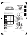 1
1
-
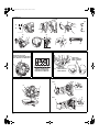 2
2
-
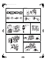 3
3
-
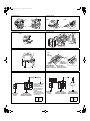 4
4
-
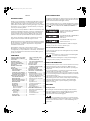 5
5
-
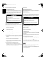 6
6
-
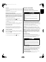 7
7
-
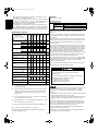 8
8
-
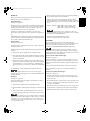 9
9
-
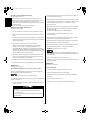 10
10
-
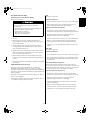 11
11
-
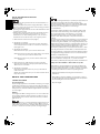 12
12
-
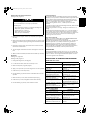 13
13
-
 14
14
-
 15
15
-
 16
16
-
 17
17
-
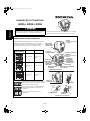 18
18
-
 19
19
-
 20
20
-
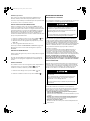 21
21
-
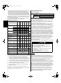 22
22
-
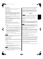 23
23
-
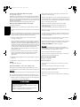 24
24
-
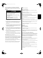 25
25
-
 26
26
-
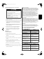 27
27
-
 28
28
-
 29
29
-
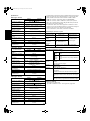 30
30
-
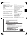 31
31
-
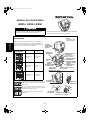 32
32
-
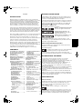 33
33
-
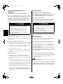 34
34
-
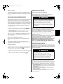 35
35
-
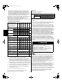 36
36
-
 37
37
-
 38
38
-
 39
39
-
 40
40
-
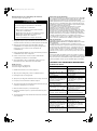 41
41
-
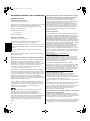 42
42
-
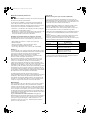 43
43
-
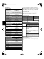 44
44
-
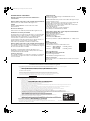 45
45
-
 46
46
-
 47
47
-
 48
48


Hubbell GX25 Le manuel du propriétaire
- Taper
- Le manuel du propriétaire
dans d''autres langues
- English: Hubbell GX25 Owner's manual
- español: Hubbell GX25 El manual del propietario
Autres documents
-
Honda GS160 Le manuel du propriétaire
-
Wacker Neuson PG1 Manuel utilisateur
-
Wacker Neuson BV35A-P Manuel utilisateur
-
Anova P100-2 Le manuel du propriétaire
-
Wacker Neuson P35A Manuel utilisateur
-
-
-
-
-
Mantis XP 7990 Le manuel du propriétaire