Sauder HomePlus 411572 Manuel utilisateur
- Taper
- Manuel utilisateur

Need help? Visit Sauder.com to view video assembly tips or chat with a live rep.
Prefer the phone? Call 1-800-523-3987.
Share your journey!
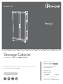
Store behind
closed doors.
NOTE: THIS INSTRUCTION
BOOKLET CONTAINS IMPORTANT
SAFETY INFORMATION.
PLEASE READ AND KEEP FOR
FUTURE REFERENCE.
English pg 1-36
Français pg 37-40
Español pg 41-44
Lot # 367954 01/08/15
Purchased: __________________
Be sure to give us a ring before
making any returns. 1-800-523-3987
Storage Cabinet
HomePlus Collection | Model 411572
sauder.com

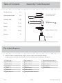
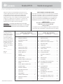
Table of Contents Assembly Tools Required
Part Identifi cation
Hardware Identifi cation
Assembly Steps
Français
Español
Safety
Warranty
Hammer
Not actual size
No. 2 Phillips Screwdriver
Tip Shown Actual Size
Electric Drill with 1/4" bit
2-3
3-4
5-36
37-40
41-44
45-46
47
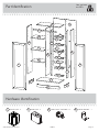
A SMALL END (1)
B LARGE END (1)
C DOOR END (1)
D UPRIGHT (1)
E TOP (1)
F BOTTOM (1)
G DOOR SHELF (3)
H DOOR UPRIGHT (1)
I LARGE SHELF (1)
J SMALL SHELF (1)
K BACK (1)
L LARGE DOOR (1)
M SMALL DOOR (1)
N LARGE ADJUSTABLE SHELF (2)
O ADJUSTABLE DOOR SHELF (3)
P SMALL ADJUSTABLE SHELF (2)
Q FRONT SKIRT (1)
R SIDE SKIRT (2)
S TOP MOLDING (1)
411572 www.sauder.com/servicesPage 2
Tape Measure
å While not all parts are labeled, some of the parts will have a label or an inked letter on the edge
to help distinguish similar parts from each other. Use this part identifi cation to help identify similar parts.
Part Identifi cation

Part Identifi cation
Now you know
our ABCs.
A
B
C
D
E
F
G
G
G
H
I
J
K
L M
N
N
O
O
O
P
P
Q
R
R
S
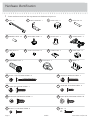
METAL BRACKET - 1
W
V
TWIST-LOCK
®
FASTENER - 27
FRONT FOOT - 2
T
REAR FOOT - 2
U
411572www.sauder.com/services
Page 3
Hardware Identifi cation

å Screws are shown actual size. You may receive extra hardware with your unit.
Hardware Identifi cation
SILVER 7/8" MACHINE SCREW - 2
NN
ADJUSTABLE FOOT - 2
JJ
ADJUSTABLE GLIDE - 4
CC
SAFETY BRACKET - 1
Y
PROPEL NUT - 4
DD
SILVER 3/4" MACHINE SCREW - 2
OO
BLACK 9/16" LARGE HEAD SCREW - 19
RR
HOLE PLUG - 8
FF
SMALL HOLE PLUG - 6
GG
SHELF SNAP - 12
II
BLACK 1-7/8" FLAT HEAD SCREW - 9
MM
BLACK 9/16" WAFER HEAD SCREW - 4
QQ
HINGE - 4
LL
RUBBER SLEEVE - 16
BB
METAL PIN - 34
AA
SILVER 5/8" FLAT HEAD SCREW - 8
PP
BLACK 1/2" FLAT HEAD SCREW - 8
SS
DOOR STOP - 2
Z
NAIL - 72
TT
FOOT BASE - 2
KK
PULL - 2
X
EE
SPRING HINGE - 3
STRIKE PLATE - 2
HH
411572 www.sauder.com/servicesPage 4

Step 1
Look for this icon. It means a
video assembly tip is available at
www.sauder.com/services/tips
å
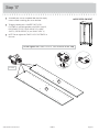
Assemble your unit on a carpeted fl oor or on the empty carton to avoid scratching your unit or the fl oor.
å
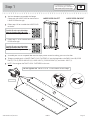
To begin assembly, push a SAUDER TWIST-LOCK® FASTENER (V) into the large holes in the ENDS (A and B), DOOR
END (C), TOP (E), DOOR SHELVES (G), LARGE SHELF (I), DOOR UPRIGHT (H), and SMALL SHELF (J).
å
NOTE: Do not tighten the TWIST-LOCK® FASTENERS at this time.
å
You have the option to assemble the Storage
Cabinet with the LARGE DOOR on the left or the
LARGE DOOR on the right.
å
Follow steps 1-16 to assemble the LARGE DOOR
on the left.
å
Follow steps 17-32 to assemble the LARGE
DOOR on the right.
LARGE DOOR ON LEFT LARGE DOOR ON RIGHT
A
B
27 used)
V
411572www.sauder.com/services
Page 5
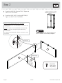
Do not tighten the TWIST-LOCK® FASTENERS in this step.
Scan this QR code or go to this address:
http://qr.sauder.com/?ID= 1133
to watch a video for the large door on the left.
Scan this QR code or go to this address:
http://qr.sauder.com/?ID= 1132
to watch a video for the large door on the right.

å
Fasten the LARGE END (B) to the TOP (E). Tighten two
TWIST-LOCK® FASTENERS.
å
Fasten the LARGE SHELF (I) to the LARGE END (B).
Tighten two TWIST-LOCK® FASTENERS.
Step 2
B
E
I
Dowel end
How to use the SAUDER TWIST-LOCK
®
FASTENER
1. Insert the dowel end of the FASTENER into the hole of the
adjoining part.
NOTE: The dowel end of the FASTENER must remain fully
inserted in the hole of the adjoining part while locking
the FASTENER.
2. Tighten the FASTENER with a Phillips screwdriver as tight
as possible.
LARGE DOOR ON LEFT
Surface with
TWIST-LOCK®
FASTENERS
411572 www.sauder.com/servicesPage 6
Do not stand the unit upright without the
BACK fastened. The unit may collapse.
Caution
Finished edge
Remember:
Righty tighty.
Lefty loosey.

å
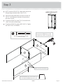
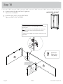
NOTE: Stand the UPRIGHT (D) in place to be sure you are
drilling through the correct holes in the TOP (E).
å
There are four pre-drilled holes in the top surface of the
TOP (E). Finish drilling out two holes with your electric
drill and 1/4" drill bit.
å
Fasten the UPRIGHT (D) to the TOP (E). Use two BLACK
1-7/8" FLAT HEAD SCREWS (MM).
å
Fasten the UPRIGHT (D) to the LARGE SHELF (I). Tighten
two TWIST-LOCK® FASTENERS.
Step 3
LARGE DOOR ON LEFT
Find the correct pre-driled holes that
line up with the UPRIGHT (D) and drill
through the top surface of the TOP (E).
These four holes must be here.
E
I
D
411572www.sauder.com/services
Page 7
BLACK 1-7/8" FLAT HEAD SCREW
(2 used in this step)
MM
34-3/4"
34-3/4"
The measurement must be as shown. If it is
not, then fl ip the UPRIGHT (D) end for end.

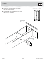
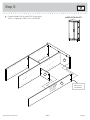
å
Fasten the TOP MOLDING (S) to the TOP (E). Tighten
three TWIST-LOCK® FASTENERS.
å
Fasten the SMALL SHELF (J) to the UPRIGHT (D). Tighten
two TWIST-LOCK® FASTENERS.
Step 4
LARGE DOOR ON LEFT
Surface with
TWIST-LOCK®
FASTENERS
Finished edge
D
E
Angled edge
S
J
411572 www.sauder.com/servicesPage 8

å
Fasten the SMALL END (A) to the TOP (E) and SMALL
SHELF (J). Tighten four TWIST-LOCK® FASTENERS.
Step 5
LARGE DOOR ON LEFT
Surface without
TWIST-LOCK®
FASTENERS
Edge with
TWIST-LOCK®
FASTENERS
A
E
J
411572www.sauder.com/services
Page 9

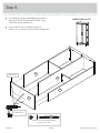
å
Finish drilling out the pre-drilled hole with your electric
drill and 1/4" drill bit to fasten the BOTTOM(F) to the
LARGE END (B) and UPRIGHT (D).
å
Fasten the BOTTOM (F) to the ENDS (A and B) and
UPRIGHT (D). Use six BLACK 1-7/8" FLAT HEAD SCREWS (MM).
Step 6
LARGE DOOR ON LEFT
Rounded edge
Unfi nished surface
Drill through these
pre-drilled holes.
A
B
D
F
411572 www.sauder.com/servicesPage 10
BLACK 1-7/8" FLAT HEAD SCREW
(6 used in this step)
MM

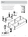
å
Slide the FEET (T and U) into the notches in the SKIRTS (Q and R).
å
Use a hammer to drive a PROPEL NUT (DD) into the holes in
the FEET (T and U). Now, turn an ADJUSTABLE GLIDE (CC)
into each PROPEL NUT as shown in the upper diagram.
å
Fasten the SKIRTS (Q and R) to the BOTTOM (F). Use four
BLACK 9/16" WAFER HEAD SCREWS (QQ) through the FEET
and into the BOTTOM as shown in the lower diagram.
Step 7
LARGE DOOR ON LEFT
This hole must be here.
CC
DD
(4 used)
Q
Q
R
R
R
R
T
T
U
U
F
BLACK 9/16" WAFER HEAD SCREW
(4 used for the FEET)
QQ
411572www.sauder.com/services
Page 11

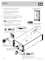
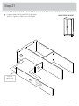
å
Carefully turn your unit over onto its front edges.
Unfold the BACK (K) and lay it over your unit.
å
Make equal margins along all four edges of the
BACK (K). Push on opposite corners of your unit if
needed to make it “square”.
å
Fasten the BACK (K) to your unit using the NAILS (TT).
å
Fasten the FOOT BASES (KK) to the BOTTOM (F). Use
eight SILVER 5/8" FLAT HEAD SCREWS (PP). Then, push
the FEET (JJ) into the FOOT BASES (KK).
å
NOTE: Turn the adjustable ends of the ADJUSTABLE
FEET completely in. Final adjustments will be made after
the unit is standing upright.
å
Fasten the METAL BRACKET (W) to the BOTTOM (F)
and FRONT SKIRT (Q). Use two BLACK 9/16" LARGE
HEAD SCREW (RR).
Step 8
LARGE DOOR ON LEFT
F
K
Q
KK
JJ
W
NAIL
(72 used for the BACK)
TT
BLACK 9/16" LARGE HEAD SCREW
(2 used for the ANGLE BRACKET)
RR
SILVER 5/8" FLAT HEAD SCREW
(8 used for the FOOT BASE)
PP
Do not stand the unit upright without the
BACK fastened. The unit may collapse.
Caution
These holes must be here.
These holes must
line up over the
UPRIGHT (D).
411572 www.sauder.com/servicesPage 12
Turn completely in.

å
Insert a METAL PIN (AA) into the holes in the DOOR END (C)
and top short edge of the DOOR SHELVES (G).
å
Fasten the DOOR SHELVES (G) to the DOOR END (C).
Tighten three TWIST-LOCK® FASTENERS.
å
Fasten the DOOR UPRIGHT (H) to the DOOR SHELVES (G).
Tighten three TWIST-LOCK® FASTENERS.
å
NOTE: Be sure the PINS insert into the edges of the
DOOR SHELVES and DOOR UPRIGHT before you tighten
the TWIST-LOCK® FASTENERS.
Step 9
LARGE DOOR ON LEFT
G
G
G
H
AA
AA
C
Plastic edge
Plastic edge
Edge with TWIST-LOCK®
FASTENERS
411572www.sauder.com/services
Page 13
Now might be a
good time to refresh
your drink.

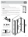
å
Fasten the STRIKE PLATES (HH) to the SMALL DOOR (M).
Use two BLACK 1/2" LARGE HEAD SCREWS (SS).
å
Fasten the PULL (X) to the SMALL DOOR (M). Use two
SILVER 3/4" MACHINE SCREWS (OO).
å
Fasten the DOOR UPRIGHT (H) and DOOR END (C) to the
SMALL DOOR (M). Tighten six TWIST-LOCK® FASTENERS.
å
Fasten the HINGES (LL) to the DOOR END (C). Use eight
BLACK 9/16" LARGE HEAD SCREWS (RR).
Step 10
LARGE DOOR ON LEFT
C
H
M
X
HH
HH
LL
BLACK 9/16" LARGE HEAD SCREW
(8 used for the HINGES)
RR
SILVER 3/4" MACHINE SCREW
(2 used for the PULL)
OO
BLACK 1/2" FLAT HEAD SCREW
(2 used for the STRIKE PLATES)
SS
IMPORTANT: The PULL (X) must
be fastened to the DOOR before the
END and UPRIGHT are fastened.
411572 www.sauder.com/servicesPage 14

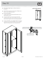
å
Carefully turn your unit over onto its BACK.
å
Place the SMALL DOOR assembly next to the SMALL
END (A). Place packing material, books or magazines
underneath the SMALL DOOR assembly for support while
you fasten the HINGES (LL) to the SMALL END.
å
Fasten the HINGES (LL) to the SMALL END (A). Use eight
BLACK 9/16" LARGE HEAD SCREWS (RR).
å
Push the DOOR STOPS (Z) into the holes in the top and
bottom corners of the UPRIGHT (D).
Step 11
LARGE DOOR ON LEFT
BLACK 9/16" LARGE HEAD SCREW
(8 used for the HINGES)
RR
Z
Z
Place packing material, books,
or magazines underneath the
SMALL DOOR for support.
A
D
411572www.sauder.com/services
Page 15

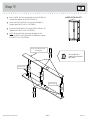
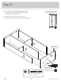
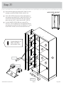
å
Fasten three SPRING HINGES (EE) to the LARGE DOOR (L).
Use six BLACK 1/2" FLAT HEAD SCREWS (SS).
Step 12
LARGE DOOR ON LEFT
EE
BLACK 1/2" FLAT HEAD SCREW
(2 used for the HINGES)
SS
411572 www.sauder.com/servicesPage 16
L

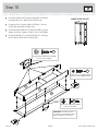
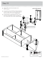
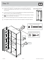
å
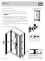
Carefully stand your unit upright.
å
Position your unit near its fi nal location.
å
Turn the ADJUSTABLE FEET (JJ) downward until they touch the fl oor.
å
IMPORTANT: The ADJUSTABLE FEET should not extend beyond the bottom edges
of the SIDE SKIRTS (R).
å
Before fastening the DOOR to your unit, be sure the mounting screw is
against the stops as shown in the left diagram. If it isn't, loosen the mounting
screw to slide it against the stops. Then tighten the mounting screw.
å
Fasten the LARGE DOOR (L) to the LARGE END (B) as shown in the lower
diagram. Use the screws in the HINGES. You should start each SCREW a few
turns before completely tightening any of them.
å
Fasten a PULL (X) to the LARGE DOOR (L). Use two BLACK 7/8" MACHINE
SCREWS (NN).
å
See the next step for DOOR adjustments.
Step 13
LARGE DOOR ON LEFT
Mounting
screw
Stop
Hinge
SILVER 7/8" MACHINE SCREW
(2 used for the PULL)
NN
X
B
L
411572www.sauder.com/services
Page 17
Turn the ADJUSTABLE FEET
downward until it touches the fl oor.
JJ
Floor
R

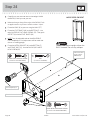
Step 14
LARGE DOOR ON LEFT
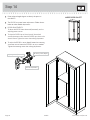
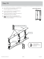
å
Refer to the enlarged diagram to identify the parts on
the HINGES.
å
The DOORS may need some adjustments. Follow the text
below to make needed adjustments.
å
DOOR ADJUSTMENTS:
To adjust the DOORS from side to side (horizontal), turn the
adjusting screw in or out.
å
To adjust the DOORS up and down (vertical), loosen both
vertical adjustment screws. Move the DOORS up or down to the
desired location. Tighten the screws after making adjustments.
å
To adjust the DOORS in or out (depth), loosen the mounting
screw one turn and move the DOORS in or out, as needed.
Tighten the mounting screw after making adjustments.
Adjusting screw (horizontal)
Mounting screw (depth)
(vertical adjustment)
411572 www.sauder.com/servicesPage 18

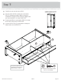
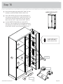
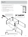
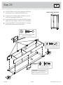
å
With a hammer, gently tap twelve SHELF SNAPS (II) into
the holes in the ADJUSTABLE DOOR SHELVES (O).
å
Insert twelve METAL PINS (AA) into the hole locations of
your choice in the DOOR END (C) and DOOR UPRIGHT (H).
Set the DOOR SHELVES onto the METAL PINS and push
down until each SHELF "snaps" into the SHELF SNAP (II).
å
Push the RUBBER SLEEVES (BB) over sixteen METAL
PINS (AA). Insert the METAL PINS into the hole locations of
your choice in the LARGE END (B) and UPRIGHT (D). Set the
ADJUSTABLE SHELVES (N and P) onto the METAL PINS.
Step 15
LARGE DOOR ON LEFT
B
C
D
N
O
O
O
O
P
P
H
BB
AA
II
II
(12 used)
(16 used)
AA
N
(12 used)
411572www.sauder.com/services
Page 19
If you're doing this to
help a friend, don't
leave without a bite.

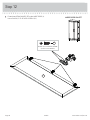
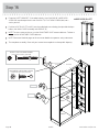
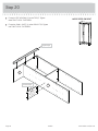
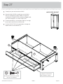
å
Fasten the SAFETY BRACKET (Y) for added stability. Use a BLACK 9/16” LARGE HEAD
SCREW (RR) into the top of the unit and a BLACK 1-7/8” FLAT HEAD SCREW (MM) into a
stud in your wall.
å
Push the HOLE PLUGS (FF and GG) into the visible holes, not including the adjustable shelf pin
holes in the SMALL DOOR assembly and UPRIGHT (D).
å
NOTE: To raise a corner of the unit, turn the ADJUSTABLE GLIDE counter-clockwise. To lower a
corner, turn the ADJUSTABLE GLIDE clockwise.
å
NOTE: Please read the back pages of the instruction booklet for important safety information.
å
This completes assembly. Clean with your favorite furniture polish or a damp cloth. Wipe dry.
Step 16
LARGE DOOR ON LEFT
RR
BLACK 9/16" LARGE HEAD SCREW
(1 used into the top of your unit)
20 lbs.
25 lbs.
30 lbs.
30 lbs.
35 lbs.
5 lbs.
5 lbs.
5 lbs.
5 lbs.
5 lbs.
5 lbs.
60 lbs.
Y
BLACK 1-7/8" FLAT HEAD SCREW
(1 used into a stud in your wall)
MM
GG
FF
No load
20 lbs.
411572 www.sauder.com/servicesPage 20
(6 used)
(8 used)
D
La page est en cours de chargement...
La page est en cours de chargement...
La page est en cours de chargement...
La page est en cours de chargement...
La page est en cours de chargement...
La page est en cours de chargement...
La page est en cours de chargement...
La page est en cours de chargement...
La page est en cours de chargement...
La page est en cours de chargement...
La page est en cours de chargement...
La page est en cours de chargement...
La page est en cours de chargement...
La page est en cours de chargement...
La page est en cours de chargement...
La page est en cours de chargement...
La page est en cours de chargement...
La page est en cours de chargement...
La page est en cours de chargement...
La page est en cours de chargement...
La page est en cours de chargement...
La page est en cours de chargement...
La page est en cours de chargement...
La page est en cours de chargement...
La page est en cours de chargement...
La page est en cours de chargement...
La page est en cours de chargement...
La page est en cours de chargement...
-
 1
1
-
 2
2
-
 3
3
-
 4
4
-
 5
5
-
 6
6
-
 7
7
-
 8
8
-
 9
9
-
 10
10
-
 11
11
-
 12
12
-
 13
13
-
 14
14
-
 15
15
-
 16
16
-
 17
17
-
 18
18
-
 19
19
-
 20
20
-
 21
21
-
 22
22
-
 23
23
-
 24
24
-
 25
25
-
 26
26
-
 27
27
-
 28
28
-
 29
29
-
 30
30
-
 31
31
-
 32
32
-
 33
33
-
 34
34
-
 35
35
-
 36
36
-
 37
37
-
 38
38
-
 39
39
-
 40
40
-
 41
41
-
 42
42
-
 43
43
-
 44
44
-
 45
45
-
 46
46
-
 47
47
-
 48
48


Sauder HomePlus 411572 Manuel utilisateur
- Taper
- Manuel utilisateur
dans d''autres langues
- English: Sauder HomePlus 411572 User manual
- español: Sauder HomePlus 411572 Manual de usuario
Documents connexes
-
Sauder 411985 Manuel utilisateur
-
-
-
-
-
-
-
-
-