Victron energy Centaur Charger Le manuel du propriétaire
- Catégorie
- Chargeurs de batterie
- Taper
- Le manuel du propriétaire

1
USER MANUAL
GEBRUIKERSHANDLEIDING
MANUEL D'UTILISATION
BEDIENUNGSANLEITUNG
MANUALE PER L'UTENTE
Centaur Charger
12/20
12/30
12/40
12/50
12/60
12/80
12/100
24/16
24/30
24/40
24/60

CCH012020000-M-bML
.

1
1. Safety and regulatory information
General
• Review related documentation of this product to familiarize yourself
with safety markings and instructions before you operate the
equipment.
• This product has been designed and tested in accordance with
international standards. Only use the equipment for the intended
purpose of application.
• WARNING: RISK OF ELECTRIC SHOCK. The product is used in
conjunction with a permanent energy source (battery). Even if the
equipment is switched off, dangerous electrical voltages may appear
at the in- and/or output terminals. Always disconnect AC power and
battery before maintaining or servicing the product.
A Ground Fault Circuit Interrupter (GFCI) must be installed in the AC
supply circuit.
• WARNING: This appliance is not intended for use by young children
or infirm persons unless they have been adequately supervised by a
responsible person to ensure that they can use the appliance safely.
Young children should be supervised to ensure that they do not play
with the appliance.
• There are no user-serviceable parts inside. Do not remove the front
plate or operate the product without the front plate fitted. Refer all
servicing to qualified personnel.
• Never use the product in locations where there is danger of gas- or
dust explosions. Consult your supplier to ensure that the product is
intended for use in conjunction with the battery. Always apply the
battery manufacturer’s safety instructions.
• Caution: never carry heavy loads without assistance.
• Explosive gases can be generated during charging of a lead-acid
battery. Prevent open flame and sparks. Take care of sufficient
ventilation during charging.
• Never try to recharge non-rechargeable batteries.
• A double-pole switch with a minimum contact distance of 3mm must
be incorporated in the fixed mains input wiring of the installation.

2
Installation
• The installation of this product must be performed by qualified
personnel.
• Always refer to the installation section in the operator’s manual
before applying power to the equipment.
• This is a Safety Class I product (provided with a protective
earthing terminal). An uninterruptible safety earth ground must be
provided at the AC in/output terminals. An additional grounding
point is located at the outside of the product. Whenever it is likely
that the grounding protection has been impaired, the product must
be made inoperative and secured against any unintended
operation; refer to qualified service personnel.
• Make sure that fuses and circuit breakers are provided in the
connecting wires. Never replace a safety component by a different
type. Consult the manual for determining the correct component.
• Make sure that all cables and wiring in the installation are
anchored in such a way that the conductors are relieved from
strain and twisting.
• Before applying power, verify that the available power source
matches the configuration settings of the product as described in
the manual.
• Ensure that the environmental conditions are suitable for
operation of the equipment. Never operate the product in a wet or
in a dusty environment.
• Always allow enough free space around the product for
ventilation and make sure that ventilation vents are not blocked.
• Be sure that the demanded power does not exceed the capacity
of the product.
• This device is a continuous duty automatic charger for
rechargeable open, sealed and gel lead acid batteries
• For supply connection use wires suitable for at least 75°C
(167°F).
• CAUTION: Replace defective cords or wires immediately.

3
Transport and storage
• When storing or transporting the product make certain that mains
power and battery leads are disconnected.
• No liability can be accepted for any transport damage when
equipment is shipped in non-original packaging.
• Store the product in a dry location; storage temperature must be
between –20°C and 60°C.
• Refer to the battery manufacturer manual concerning transport,
storage, charging, recharging and disposal of the battery.

4
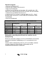
2. Description
Technology
The Centaur Charger is a fully high-frequency switched battery
charger. The input is electronically power factor corrected by the
first power stage.
The next stage gives provision for galvanic isolation and a perfect
DC voltage at the output terminals.
The internal electronic parts are protected against moisture and
dirt by means of a special coating, which assures a long lifetime of
your battery charger.
Three high-capacity batteries can be charged simultaneously with
this charger.
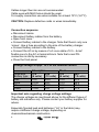
Operation
The battery charger charges the battery with 3-stage (Bulk-
Absorption-Float) charging characteristic. It can remain connected
to the battery continuously, without increased gas formation,
caused by overcharging, taking place.
The charger can be used for different types of batteries but the
default settings are for Gel batteries.
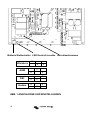
For use with other types of batteries please select Lead acid or
AGM by opening front bottom cover and select DIP switch in
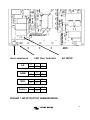
bottom left hand corner. See Figure 1.
The full charging current of this Charger is divided in three main
outputs but any one output can supply 100% of power if that is the
only battery connected.

5
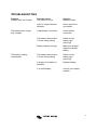
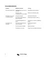
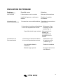
TROUBLESHOOTING
Problem Possible cause Solution
Charger does not function The mains is not ok Measure mains
Input or output fuses are Return product to
defective your dealer
The battery does not get A bad battery connection Check battery
fully charged connection
The battery select switch Select correct
is in the wrong setting battery type
(see Fig1)
Battery capacity to large Make sure charger
capacity matches
battery
The battery is being The battery select switch Select correct
overcharged is in the wrong setting battery type
(see Fig1)
A single cell in battery is Replace battery
defective
Too small battery Consult your battery
supplier

6
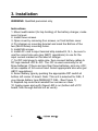
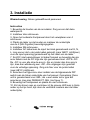
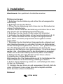
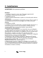
3. Installation
WARNING: Qualified personnel only
Instructions
1. Mount wall bracket (for top holding) of the battery charger, make
sure it is level.
2. Install three screws.
3. Open cover by removing four screws, on front bottom cover.
4. Put charger on mounting bracket and mark the Bottom of the
two (M6-D-holes) mounting holes.
5. Install M6 screws.
6. Install AC cord to input terminal strip marked E, N, L, be sure to
use the correct size wire (per ABYC regulations) to use for the
input current marked on the label of charger.
7. Cut DC inlet plugs to cable size, then connect battery cables to
DC lugs marked +DC & -DC. The -DC is used commonly for all
three batteries. If there are less than three batteries, pick any +DC;
all are capable of full current load. Select appropriate size wire (per
ABYC regulations).
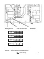
8. Select battery type by pushing the appropriate DIP switch at
bottom left corner of board. Note: This unit is selected for GEL; if
you change battery type DESELECT GEL, (See Figure 1).
9. Replace top cover and reinstall four screws on cover.
10. Apply power and verify Green LED is on (bottom left of PC
board, look through bottom left air vents).

7
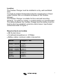
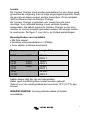
Location
The Centaur Charger must be installed in a dry, well-ventilated
area.
Too high an ambient temperature has the consequence of lower
output, shorter life or a complete shutdown of the Centaur
Charger.
The Centaur Charger is suitable for floor and wall mounting.
However, for optimum cooling, a vertical position is recommended.
The cables between the Centaur Charger and the battery must be
kept as short as possible to minimize cable losses. Input/output
connections refer to Figure 1.
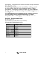
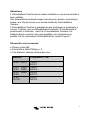
Required tools and cables
• M6 Socket driver.
• Crosshead screwdriver no. 2 Phillips.
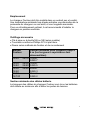
• Battery cables: minimum cable cross-section
Model
Length 0 - 6m
12/20 24/16
10mm²
AWG 7
12/30 24/30
12/40 24/40
16mm²
AWG 5
12/50 24/60
12/60
25mm²
AWG 3
12/80
12/100
35mm²
AWG 2

8
Cables longer then 6m are not recommended.
Cable eyes with M6/8 holes should be used.
For supply connection use wires suitable for at least 75°C (167°F).
CAUTION: Replace defective cords or wires immediately.
Connection sequence
• Disconnect mains.
• Disconnect battery cables from the battery.
• Open front cover.
• Connect battery cables to the charger. Note that there’s only one
‘minus’- Use a fuse according to the size of the battery charger.
• Connect battery cables to the battery.
• Connect the AC-in by means of a 3-core cable of 2.5 – 4mm²
flexible core to the AC-in terminal block. Note that a real PE-
connection is strictly necessary.
• Close the front panel.
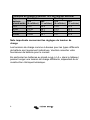
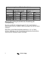
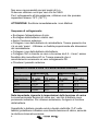
Charge voltage at appr. 10% of the nominal current
Absorption
Float
Lead-acid
Battery type
12V
(6 cells)
24V
(12 cells)
12V
(6 cells)
24V
(12 cells)
GEL
14.2
28.4
13.5
27.0
AGM
14.35
28.7
13.3
26.6
LA
14.5
29.0
13.5
27.0
Other
14.85
29.7
13.7
27.4
Important note regarding charge voltage settings
The charge voltages as mentioned above for the different types of
battery are indicative only. Please contact your battery supplier for
advice.
Especially flooded lead acid batteries (“LA” in the table) may
require a different charge voltage, depending on
chemical/mechanical construction.

9
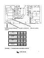
+ + + -DC
Battery Select LED ‘ON’ Indicator AC INPUT
LA
II
II
II
AGM
II
II
II
GEL
II
II
II
Other
II
II
II
FIGURE 1 INPUT/ OUTPUT CONNECTIONS

10
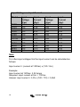
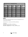
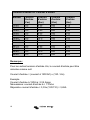
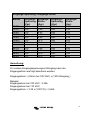
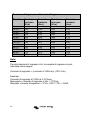
Input Voltage vs. Input Current
Model
Input
Voltage
(Vac)
Input
Current
(Aac)
Input
Voltage
(Vac)
Input
Current
(Aac)
12/20
120
3.35
240
1.75
12/30
120
4.35
240
2.30
12/40
120
6.40
240
3.20
12/50
120
8.00
240
4.00
12/60
120
9.55
240
4.75
12/80
120
12.0
240
6.00
12/100
120
15.0
240
8.00
24/16
120
5.55
240
2.50
24/30
120
9.00
240
4.55
24/40
120
10.0
240
6.00
24/60
120
15.0
240
9.00
Note:
For other input voltages Uin the input current can be calculated as
follows:
Input current = (current at 120Vac) x (120 / Uin)
Example:
Input current at 120Vac: 3,35 Amps
Required: input current at Uin = 110Vac
Answer: input current = 3,35 x (120 / 110) = 3,65A

11
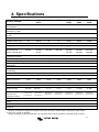
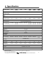
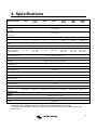
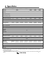
4. Specifications
Centaur Charger
12/20
12/30
24/16
12/40
12/50
12/60
24/30
12/80
24/40
12/100
24/60
Common
characteristics
Input voltage: 90 – 265V Input frequency: 45 – 65Hz Power factor: 1
Charge voltage
‘absorption’ (V DC)
14,3 / 28,5 (1)
Charge voltage ‘float’
(V DC)
13,5 / 27,0 (1)
Output banks
3
Charge current (A) (2) 20 30/16 40 50 60/30 80/40 100/60
Total output ammeter
Yes
Charge characteristic
IUoU (Three stage charging)
Recommended
battery capacity (Ah)
80-200
120-300
45-150
160-400
200-500
240-600
120-300
320-800
160-400
400-1000
240-600
Temperature sensor
Internal, - 2mV / °C (- 1mV / °F) per cell
Forced cooling
Yes, temperature and current controlled fan
Protection
Output short circuit, over temperature
Operating
temp range
- 20 to 60°C (0 - 140°F)
Ignition protected Yes
Humidity (non-
condensing)
max 95%
ENCLOSURE
Material & Colour aluminium (blue RAL 5012)
Battery-connection
M6
studs
M6
studs
M8
studs
M8
studs
M8
studs
M8
studs
M8
studs
AC-connection screw-clamp 4mm² (AWG 6)
Protection category IP 20
Weight kg (lbs) 3,8 (8.4) 3,8 (8.4) 5 (11) 5 (11) 5 (11) 12 (26) 12 (26)
Dimensions
hxwxd in mm
(hxwxd in inches)
355x215x110
(14.0x8.5x4.3)
355x215x110
(14.0x8.5x4.3)
426x239x135
(16.8x9.4x5.3)
426x239x135
(16.8x9.4x5.3)
426x239x135
(16.8x9.4x5.3)
505x255x130
(19.9x10.0x5.2)
505x255x130
(19.9x10.0x5.2)
STANDARDS
Safety
EN 60335-2-29, UL 1236
Emission
EN 55014, EN 61000-3-2, EN 61000-3-3
Immunity
EN 55014-2
1) Standard setting.
Optimum charge/float voltages for Flooded Lead-acid, Gel-Cell or AGM batteries selectable by DIP switch.
2) Up to 40 °C (100 °F) ambient.
Output will reduce to approximately 80 % of nominal at 50°C (120°F) and 60% of nominal at 60°C (140°F).


1
1. Veiligheidsvoorschriften
Algemeen
• Lees eerst de bij dit product geleverde documentatie, zodat u
bekend bent met de veiligheidsaanduidingen en aanwijzingen
voordat u de apparatuur in gebruik neemt.
• Dit product is ontworpen en getest in overeenstemming met de
internationale normen. De apparatuur dient uitsluitend voor de
bestemde toepassing te worden gebruikt.
• WAARSCHUWING: KANS OP ELEKTRISCHE SCHOKKEN.
Het product wordt gebruikt in combinatie met een permanente
energiebron (batterij). Zelfs als de apparatuur is uitgeschakeld, kan
een gevaarlijke elektrische spanning optreden bij de in- en/of
uitgangsklemmen. Schakel altijd de wisselstroomvoeding en de
batterij uit voor het plegen van onderhoud.
• Het product bevat geen interne onderdelen die door de gebruiker
kunnen worden onderhouden. Haal het paneel aan de voorkant er
niet af en stel het product niet in werking als niet alle panelen zijn
gemonteerd. Al het onderhoud dient door gekwalificeerd personeel
te worden uitgevoerd.
• Gebruik het product nooit op plaatsen waar gas- of stofexplosies
kunnen optreden. Raadpleeg de gegevens van de fabrikant van de
batterij om u ervan te verzekeren dat het product bestemd is voor
gebruik in combinatie met de batterij. De veiligheidsvoorschriften
van de fabrikant van de batterij dienen altijd te worden opgevolgd.
• WAARSCHUWING: Til geen zware lasten zonder hulp.
• Explosieve gassen kunnen ontstaan tijdens het laden van een
lood zuur accu. Voorkom open vuur en vonken. Zorg voor
voldoende ventilatie tijdens het laden.

2
Installatie
• De installatie van dit product moet worden uitgevoerd door
gekwalificeerd personeel.
• Refereer altijd naar de installatie instructies in de
gebruiksaanwijzing voor de ingebruikname van de apparatuur.
• Dit is een product uit veiligheidsklasse I (dat wordt geleverd met
een aardklem ter beveiliging). De in- en/of uitgangsklemmen van
de wisselstroom moeten zijn voorzien van een ononderbreekbare
aarding ter beveiliging. Aan de buitenkant van het product bevindt
zich een extra aardingspunt. Als het aannemelijk is dat de
aardbeveiliging is beschadigd, moet het product buiten werking
worden gesteld en worden beveiligd tegen iedere onopzettelijke
inwerkingstelling; neem contact op met gekwalificeerd
onderhoudspersoneel.
• Zorg ervoor dat de aansluitkabels zijn voorzien van zekeringen
en stroomonderbrekers. Vervang een beveiligingsonderdeel nooit
door een ander type. Raadpleeg de handleiding voor het juiste
onderdeel.
• Controleer voordat u het apparaat inschakelt, dat de beschikbare
spanningsbron overeenkomt met de configuratie-instellingen van
het product zoals beschreven in de handleiding.
• Zorg ervoor dat de apparatuur onder de juiste
bedrijfsomstandigheden wordt gebruikt. Stel het product nooit in
bedrijf in de regen of in een stoffige omgeving.
• Zorg ervoor dat er altijd voldoende vrije ruimte rondom het
product is voor ventilatie en dat de ventilatie openingen niet zijn
geblokkeerd.
• Verzeker u ervan dat de vereiste spanning niet hoger is dan de
capaciteit van het product.
• Dit product is een ononderbroken automatische lader voor
herlaadbare open, gesloten en GEL lood zuur accu’s.
• Gebruik voor de voeding kabels die tenminste 75°C (167°F) aan
kunnen.
• WAARSCHUWING: Vervang defecte kabels of draden
onmiddellijk.

3
Vervoer en opslag
• Zorg ervoor dat de netspanning en batterijkabels zijn
losgekoppeld bij opslag of vervoer van het product.
• Er kan geen aansprakelijkheid worden aanvaard voor
transportschade indien de apparatuur wordt vervoerd in een
andere dan de originele verpakking.
• Sla het product op in een droge omgeving; de opslagtemperatuur
moet tussen de –20°C en 60°C liggen.
• Raadpleeg de handleiding van de fabrikant van de batterij met
betrekking tot vervoer, opslag, opladen, herladen en verwijderen
van de batterij.

4
2. Beschrijving
Technologie
De Centaur lader is een hoog frequente geschakelde acculader.
De input is een elektronische stroom factor gecorrigeerd door de
eerste stap.
De tweede stap geeft provisie voor galvanische isolatie en biedt
perfecte DC voltage bij de uitgangen.
The interne elektronische onderdelen zijn voorzien van een
speciale coating die beschermt tegen vocht en stof wat zorgt voor
een lange levensduur van uw acculader.
Drie hoge-capaciteit accu’s kunnen tegelijk worden geladen met
deze lader.
Gebruik
De acculader laadt de accu’s met een 3-staps (Bulk-Absorption-
Float) laad karakteristiek. De lader kan aangesloten blijven op de
accu’s zonder extra gas vorming door het laden van een volle
accu.
De lader kan worden gebruikt voor verschillende soorten accu’s
maar de standaard instelling is voor een GEL accu.
Voor gebruik met andere accu’s kunt u het onderste deel van het
front openen en daar door middel van de DIP switches links
onderin kiezen voor een lood-zuur of AGM accu. Zie Fig1.
De volledige laadstroom van deze lader is verdeeld over 3
uitgangen maar kan ook 100% geven over 1 uitgang als er maar 1
accu aangesloten is.

5
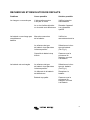
PROBLEMEN
Probleem
Mogelijke oorzaak
Oplossing
Lader werkt niet
De hoofdstroom is niet ok
Meet de hoofdstroom na
De in of output zekeringen
zijn defect
Breng het product terug naar
uw dealer
De accu wordt niet vol
geladen
Een slechte accu connectie
Controleer de accu
connectie
De accu DIP switch staat
verkeerd
Selecteer de juiste accu. Zie
Fig1.
Accu capaciteit is te groot
Verzeker uzelf dat de
capaciteit van de lader
overeenkomt met de accu
De accu wordt te lang
geladen
De accu DIP switch staat
verkeerd
Selecteer de juiste accu. Zie
Fig1.
Een enkele cel in de accu is
defect
Vervang de accu
Een te kleine accu
Vraag advies van uw accu
leverancier

6
3. Installatie
Waarschuwing: Alleen gekwalificeerd personeel
Instructies
1. Bevestig de houder van de acculader. Zorg ervoor dat deze
waterpas is.
2. Installeer drie schroeven.
3. Open het onderste frontpaneel door het verwijderen van 4
schroeven.
4. Plaats de lader op de houder en markeer de onderzijde
van de 2 (M6-D-gaten) bevestigingsgaten
5. Installeer M6 schroeven.
6. Installeer AC kabel aan de input terminal gemarkeerd met E, N,
L, zorg ervoor dat u de juiste kabel gebruikt (naar ABYC richtlijnen)
voor de input spanning gemarkeerd op het label van de lader.
7. Snij DC inlet aansluitingen tot kabel formaat en bevestig dan de
accu kabels met de DC lugs die zijn gemarkeerd met +DC & -DC.
De –DC is voor alle drie de accu’s. Als er minder dan drie accu’s
zijn, kies dan willekeurig een +DC. Alle uitgangen zijn geschikt
voor de volledige spanning. Zorg ook hier voor de juiste kabel
(naar ABYC richtlijnen).
8. Selecteer het type accu door middel van de bijpassende DIP
switch aan de linker onderzijde van het paneel. Opmerking: Deze
unit is geselecteerd voor GEL; als u een ander accu type wilt
selecteren, kies dan DESELECT GEL (zie figuur 1).
9. Bevestig het frontpaneel en plaats de vier schroeven.
10. Zet de stroom aan en controleer of de groene LED aan is (links
onder op het pc bord, kijk door de ventilatie roosters aan de linker
onderzijde).
La page est en cours de chargement...
La page est en cours de chargement...
La page est en cours de chargement...
La page est en cours de chargement...
La page est en cours de chargement...
La page est en cours de chargement...
La page est en cours de chargement...
La page est en cours de chargement...
La page est en cours de chargement...
La page est en cours de chargement...
La page est en cours de chargement...
La page est en cours de chargement...
La page est en cours de chargement...
La page est en cours de chargement...
La page est en cours de chargement...
La page est en cours de chargement...
La page est en cours de chargement...
La page est en cours de chargement...
La page est en cours de chargement...
La page est en cours de chargement...
La page est en cours de chargement...
La page est en cours de chargement...
La page est en cours de chargement...
La page est en cours de chargement...
La page est en cours de chargement...
La page est en cours de chargement...
La page est en cours de chargement...
La page est en cours de chargement...
La page est en cours de chargement...
La page est en cours de chargement...
La page est en cours de chargement...
La page est en cours de chargement...
La page est en cours de chargement...
La page est en cours de chargement...
La page est en cours de chargement...
La page est en cours de chargement...
La page est en cours de chargement...
La page est en cours de chargement...
La page est en cours de chargement...
La page est en cours de chargement...
La page est en cours de chargement...
La page est en cours de chargement...
La page est en cours de chargement...
-
 1
1
-
 2
2
-
 3
3
-
 4
4
-
 5
5
-
 6
6
-
 7
7
-
 8
8
-
 9
9
-
 10
10
-
 11
11
-
 12
12
-
 13
13
-
 14
14
-
 15
15
-
 16
16
-
 17
17
-
 18
18
-
 19
19
-
 20
20
-
 21
21
-
 22
22
-
 23
23
-
 24
24
-
 25
25
-
 26
26
-
 27
27
-
 28
28
-
 29
29
-
 30
30
-
 31
31
-
 32
32
-
 33
33
-
 34
34
-
 35
35
-
 36
36
-
 37
37
-
 38
38
-
 39
39
-
 40
40
-
 41
41
-
 42
42
-
 43
43
-
 44
44
-
 45
45
-
 46
46
-
 47
47
-
 48
48
-
 49
49
-
 50
50
-
 51
51
-
 52
52
-
 53
53
-
 54
54
-
 55
55
-
 56
56
-
 57
57
-
 58
58
-
 59
59
-
 60
60
-
 61
61
-
 62
62
-
 63
63


Victron energy Centaur Charger Le manuel du propriétaire
- Catégorie
- Chargeurs de batterie
- Taper
- Le manuel du propriétaire
dans d''autres langues
Documents connexes
-
Victron energy 12/200 Manuel utilisateur
-
-
-
-
-
-
-
-
-
