Hitachi CG 25EUAP Safety Instructions And Instruction Manual
- Catégorie
- Coupe-herbe
- Taper
- Safety Instructions And Instruction Manual

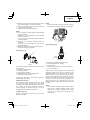
SAFETY INSTRUCTIONS AND INSTRUCTION MANUAL
WARNING
IMPROPER OR UNSAFE use of this power tool can result in death or serious bodily injury!
This manual contains important information about product safety. Please read and understand this manual
BEFORE operating the power tool. Please keep this manual available for other users and owners before they
use the power tool. This manual should be stored in safe place.
INSTRUCTIONS DE SECURITE ET MODE D’EMPLOI
AVERTISSEMENT
Une utilisation INCORRECTE OU DANGEREUSE de cet outil motorisé peut entraîner la mort ou de
sérieuses blessures corporelles !
Ce mode d’emploi contient d’importantes informations à propos de la sécurité de ce produit. Prière de
lire et de comprendre ce mode d’emploi AVANT d’utiliser l’outil motorisé. Garder ce mode d’emploi à la
disponibilité des autres utilisateurs et propriétaires avant qu’ils utilisent l’outil motorisé. Ce mode d’emploi
doit être conservé dans un endroit sûr.
INSTRUCCIONES DE SEGURIDAD Y MANUAL DE INSTRUCCIONES
ADVERTENCIA
¡La utilización INAPROPIADA O PELIGROSA de esta herramienta eléctrica puede provocar lesiones
graves o la muerte!
Este manual contiene información importante sobre la seguridad del producto. Lea y comprenda este
manual ANTES de utilizar la herramienta eléctrica. Guarde este manual para que puedan leerlo otras
personas antes de utilizar la herramienta eléctrica. Este manual debe ser guardado en un lugar seguro.
CG 25EUAP (L)
Grass Trimmer
Coupe-Herbes
Motoguadañas
Designed for operating in USA & Canada only.
When this product is used in areas other than the USA & Canada,
we cannot guarantee the product quality and performance.

2
English
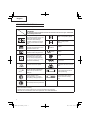
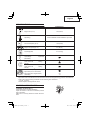
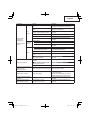
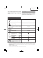
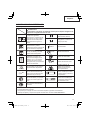
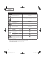
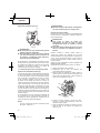
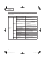
MEANINGS OF SYMBOLS
NOTE: Some units do not carry them.
Symbols
WARNING
The following show symbols used for the machine. Be sure that you understand
their meaning before use.
It is important that you read,
fully understand before use, and
observe the following safety
precautions and warnings.
Careless or improper use of the
unit may cause serious or fatal
injury.
Choke - Run position (Open)
Choke - Start position
(Closed)
Read, understand and follow all
warnings and instructions in this
manual and on the unit.
START
On/Start
Always wear eye, head and ear
protectors when using this unit.
STOP
Off /Stop
Keep all children, bystanders
and helpers 15 m away from
the unit. If anyone approaches
you, stop the engine and cutting
attachment immediately.
Fuel fi ll
Engine oil fi ll
Be careful of thrown objects.
Hot surface – Contact with
hot surface can cause serious
burns.
min
-1
Shows maximum shaft speed. Do
not use the cutting attachment
whose max rpm is below the
shaft rpm.
Indicate handle location.
Arrows which show limits for
handle positioning.
Gloves should be worn
when necessary, e.g., when
assembling cutting equipment.
Indicates cutting attachment
guard location for a trimmer
head or semi-auto cutting
head.
Use anti-slip and sturdy footwear.
Before using your machine
• Read the manual carefully.
• Check that the cutting equipment is correctly assembled and adjusted.
• Start the unit and check the carburetor adjustment. See “MAINTENANCE”.

3
English
15
16
17
18
Contents
WHAT IS WHAT .................................................... 3
WARNINGS AND SAFETY INSTRUCTIONS ........ 4
WARRANTY .......................................................... 6
SPECIFICATIONS ................................................. 7
ASSEMBLY PROCEDURES ................................. 7
OPERATING PROCEDURES ................................ 9
MAINTENANCE .................................................. 12
TROUBLESHOOTING......................................... 16
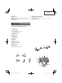
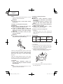
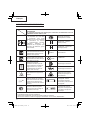
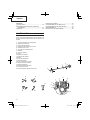
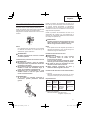
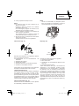
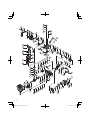
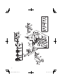
WHAT IS WHAT
Since this manual covers several models, there may
be some diff erence between pictures and your unit.
Use the instructions that apply to your unit.
1. Fuel cap
2. Throttle trigger
3. Starter handle
4. Cutting attachment guard
5. Cutting attachment
6. Drive shaft tube
7. Handle
8. Ignition switch
9. Spark plug
10. Priming Pump
11. Choke lever
12. Engine
13. Gear case
14. Oil cap
15. Combi box spanner
16. Handling instructions
17. Goggles
18. Hex. bar wrench
19. Engine cover
20. Engine oil measuring cup
3
11
10
1
12
19
14
9
12
8
7
6
13
5
4
2
20

4
English
WARNING
The engine exhaust from this product contains
chemical known to the State of California to cause
cancer, birth defects or other reproductive harm.
WARNINGS AND SAFETY
INSTRUCTIONS
Pay special attention to statements preceded by the
following words:
WARNING
Indicates a strong possibility of severe personal
injury or loss of life, if instructions are not
followed.
CAUTION
Indicates a possibility of personal injury or
equipment damage, if instructions are not
followed.
NOTE
Helpful information for correct function and use.
Operator safety
○ Always wear a safety face shield or goggles.
○ Approved protective goggles comply with
standard ANSI Z87.1 in the USA.
○ Always wear heavy, long pants, non-slip boots,
gloves and a long-sleeve shirt. Do not wear
loose clothing, jewelry, short pants, sandals or
go barefoot. Secure hair so it is above shoulder
length.
○ Do not operate this tool when you are tired,
ill or under the infl uence of alcohol, drugs or
medication.
○ Never let a child or inexperienced person operate
the machine.
○ Wear approved hearing protection.
Long-term exposure to noise can result in
permanent hearing impairment.
Pay attention to your surroundings. Be aware of
any bystanders who may be signaling a problem.
Remove safety equipment immediately upon
shutting off engine.
○ Wear head protection.
○ Never start or run the engine inside a closed
environment, such as a room or building.
Breathing carbon monoxide exhaust fumes can
kill.
○ Keep handles free of oil and fuel.
○ Keep hands away from cutting equipment.
○ Do not grab or hold the unit by the cutting
equipment.
○ When the unit is turned off , make sure the cutting
attachment has stopped before the unit is set
down.
○ When operation is prolonged, take a break from
time to time so that you may avoid possible
Hand-Arm Vibration Syndrome (HAVS) which is
caused by vibration.
○ Do not operate the tool at night or under bad
weather conditions when visibility is poor. And do
not operate the tool when it is raining or right after
it has been raining.
Working on slippery ground could lead to an
accident if you lose your balance.
○ Do not start the engine if there are any
fl ammables such as dry leaves, waste paper or
fuel in the vicinity.
○ Gloves should be worn when installing or
removing the cutting attachment. Failure to do so
may result in injury.
WARNING
● Always operate the tool with proper
protective equipment and clothing. Failure to
do so may result in accidents such as burns
or injuries.
● Do not touch the spark plug area or high
voltage during operation. Doing so may
result in electric shock.
● Do not allow children near the tool during
operation.
● Do not touch the engine, engine cover
or exhaust vent during or shortly after
operation. Doing so may result in burn or
injury.
● Antivibration systems do not guarantee that
you will not sustain Hand-Arm Vibration
Syndrome or carpal tunnel syndrome.
Therefore, continual and regular users
should monitor closely the condition of
their hands and fi ngers. If any symptoms
of the above appear, seek medical advice
immediately.
● If you are using any medical electric/
electronic devices such as a pacemaker,
consult your physician as well as the device
manufacturer prior to operating any power
equipment.
Unit/machine safety
○ Inspect the entire unit/machine before each use.
Replace damaged parts. Check for fuel leaks
and make sure all fasteners are in place and
securely tightened.

5
English
○ Replace parts that are cracked, chipped or
damaged in any way before using the unit/
machine. Faulty parts may increase the risk of
accidents and may lead to an injury.
○ Make sure the cutting attachment is properly
installed and securely fastened.
○ Make sure the cutting attachment guard is
properly attached. Do not operate if cutting
attachment guard is not properly attached.
○ Keep others away when making carburetor
adjustments.
○ Use only accessories as recommended for this
unit/machine by the manufacturer.
○ Before operation, make sure that there are no
tools such as the adjustment key or spanner still
attached to the unit.
WARNING
● Never modify the unit/machine in any way.
Do not use your unit/machine for any job
except that for which it is intended.
● Non-authorized modifi cations and/or
accessories may result in serious personal
injury or the death of the operator or others.
Fuel safety
○ Pour fuel outdoors and where there are no
sparks and fl ames.
○ Use a container approved for fuel.
○ Move at least 10 ft (3 m) away from fueling site
before starting engine.
○ Slowly remove the fuel cap only after stopping
the engine. Do not remove the fuel cap during
operation.
○ Empty the fuel tank before storing the unit/
machine. It is recommended that the fuel be
emptied after each use. If fuel is left in the tank,
store so fuel will not leak.
WARNING
● Fuel is easy to ignite or get explosion or
inhale fumes, so that pay special attention
when handling or fi lling fuel.
● Do not smoke or allow smoking near fuel
or the unit/machine or while using the unit/
machine and fueling.
● Wipe up all fuel spills before starting engine.
● Store unit/machine and fuel in area where
fuel vapors cannot reach sparks or open
fl ames from water heaters, electric motors or
switches, furnaces. etc.
● When using the unit in dry areas, make sure
that fi re extinguishing equipment is readily
available.
● If you shut off the engine for refueling, make
sure the unit has cooled down before adding
fuel.
Cutting safety
○ Do not cut any material other than grass and
brush.
○ Clear the area to be cut before each use.
Remove objects which can be thrown or become
entangled in the cutting attachment.
○ For respiratory protection, wear an aerosol
protection mask when cutting the grass after
insecticide is scattered.
○ Keep others including children, animals,
bystanders and helpers outside the 50 ft (15 m)
hazard zone. There is still a risk of injury from
thrown object. Bystanders should be encouraged
to wear eye protection. Stop the engine
immediately if you are approached.
○ Please exercise caution as engine startup may
be delayed after pulling the starter handle.
○ Always keep the engine on the right side of your
body.
○ Hold the unit/machine fi rmly with both hands.
○ Keep fi rm footing and balance. Do not over-
reach.
Losing your balance during work may lead to an
injury.
○ Keep all parts of your body away from the muffl er
and cutting attachment when the engine is
running.
○ Keep cutting attachment below knee level.
○ Please exercise caution when operating in areas
where electrical cables or gas pipes are present.
○ Do not operate the cutting attachment for
anything but clearing grass or bushes. Avoid
operations where the cutting attachment may
touch water such as puddles or dig into dirt.
Failure to do so may result in injury or damage to
the unit.
○ Avoid prolonged use at low speed range in which
vibration is high. Doing so may result in engine
damage.
○ When relocating to a new work area, or
inspecting, adjusting or exchanging the unit’s
cutting attachments, accessories, etc., be sure
to shut off the machine and ensure that all cutting
attachments are stopped.
○ Never place the machine on the ground when
running.
○ Never touch the cutting attachment when it is
rotating.
○ Always ensure that the engine is shut off and any
cutting attachments have completely stopped
before clearing debris or removing grass from the
cutting attachment.

6
English
○ Always carry a fi rst-aid kit when operating any
power equipment.
○ Turn off the engine and make sure the cutting
attachment has come to a full stop before
removing the unit from your body or before
leaving the unit unattended.
○ If you accidentally bump or drop the unit,
inspect it immediately to make sure there are no
damage, cracks or deformations.
○ If the tool is operating poorly and produces
strange noise or vibrations, turn off the engine
immediately and ask your dealer to have it
inspected and repaired.
Continued use under these conditions could lead
to injury or tool damage.
○ Use in accordance with local laws and
regulations.
Maintenance safety
○ Maintain the unit/machine according to
recommended procedures.
○ Disconnect the spark plug before performing
maintenance except for carburetor adjustments.
○ Keep others away when making carburetor
adjustments.
○ Use only genuine Hitachi replacement parts as
recommended by the manufacturer.
CAUTION
Do not disassemble the recoil starter. There
is a possibility of personal injury with recoil
spring.
WARNING
Improper maintenance could result in
serious engine damage or in serious
personal injury.
Transport and storage
○ Carry the unit/machine by hand with the engine
stopped and the muffl er away from your body.
○ Allow the engine to cool, empty the fuel tank,
and secure the unit/machine before storing or
transporting. Failure to do so may result in fi re or
accidents.
○ Empty the fuel tank before storing the unit/
machine. It is recommended that the fuel be
emptied after each use. If fuel is left in the tank,
store so fuel will not leak.
○ Store unit/machine out of the reach of children.
○ Clean and maintain the unit carefully and store it
in a dry place.
○ Make sure engine switch is off when transporting
or storing.
○ When transporting and storing, either remove the
cutting attachment or place the blade cover over
the blade.
○ You have to secure the machine during transport
to prevent loss of fuel, damage or injury.
If situations occur which are not covered in this
manual, take care and use common sense. Contact
Hitachi Authorized Service Centers if you need
assistance.
WARRANTY
The warranties provided by Hitachi Koki U.S.A., Ltd.
are explained in the warranty card enclosed with this
product titled “Hitachi Outdoor Power Equipment
Limited Warranty”.

7
English
SPECIFICATIONS
Model CG25EUAP (L)
Engine Size (cu. in.) 1.53 (25 mℓ)
Spark Plug TORCH CMR5H or NGK CMR5H or equivalent
Fuel Tank Capacity (fl . oz) 18.6 (0.55ℓ)
Engine Oil Capacity (fl . oz) 2.7 (80 mℓ)
Dry Weight (lbs) 12.1 (5.5 kg)
Sound pressure level
LpA (dB (A))
(ISO22868)
Equivalent
91
Measured sound
power level LwA
(dB (A))
(
ISO
22868)
Racing
110
Guaranteed sound
power level LwA
(dB (A))
(
ISO
22868)
Racing
113
Vibration level (m/s
2
) (ISO22867)
Equivalent (Front / Left handle)
Equivalent (Rear / Right handle)
Uncertainty
7.0
5.2
1.5
NOTE
Equivalent noise level/vibration level are calculated as the time-weighted energy total for noise/vibration
levels under various working conditions with the following time distribution:
* 1/2 idle, 1/2 racing.
All data subject to change without notice.
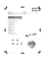
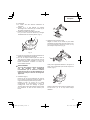
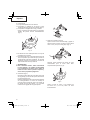
ASSEMBLY PROCEDURES
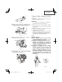
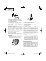
Installation of handle (Fig. 1)
Attach the handle to the drive shaft tube.
Adjust the location to the most comfortable position
before operation.
Make sure to securely attach the handle with the 4
bolts.
1
Fig. 1

8
English
NOTE
If your unit has handle location label (1) on drive
shaft tube, follow the illustration.
WARNING
Do not use metal or plastic blade cutting
attachments.
Installation of cutting attachment guard
WARNING
● Do not start or operate unit unless each
guard is properly assembled to unit.
● lf unit is operated without a sharp line
limiters, the line will become too long, the
engine will overheat, and engine damage
may occur.
● Check sharp line limiters surely cut nylon
line when operating.
WARNING
If an incorrect or faulty guard is fi tted, this
may cause serious personal injury.
2
4
3
Fig. 2
Install the cutting attachment guard on drive shaft
tube against angle transmission. Tighten the guard
bracket (2) fi rmly so that the cutting attachment
guard does not swing or move down during
operation.
Install the cutting attachment guard to the guard
bracket (2), which also secures the guard to the gear
case using the two guard mounting screws (3).
CAUTION
Some cutting attachment guards are
equipped with sharp line limiters. Be careful
with handling it.
NOTE
If your unit has guard location label (4) on drive
shaft tube, follow the indication.
Installation of cutting attachment
WARNING
● Install the cutting attachment properly
and securely as instructed in the handling
instructions.
If not attached properly or securely, it may
come off and cause serious and/or fatal
injury.
● Do not install or remove cutting attachments
while the engine is running.
● Always use genuine Hitachi cutting
attachments and metal fi ttings.
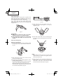
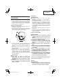
Installation of semi-auto cutting head
1. Function
Automatically feeds more nylon cutting line
when it is tapped at low rpm (not greater than
6,000 min
–1
).
Specifi cations
Code No.
Type of
attaching
screw
Direction of
rotation
Size of
attaching
screw
6600570
Female
screw
Counterclockwise
M10×P1.25-
LH
Applicable nylon cord
Cord diameter: 3/22˝ (Φ2.4 mm) Length: 16.4 ft (5 m)
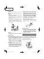
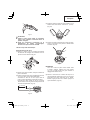
2. Precautions
○ The case must be securely attached to the cover.
○ Check the cover (5), case (6) and other
components for cracks or other damage. (Fig. 3)
○ Check the case and button for wear.
If there is a hole in the bottom (7) of the button,
change the new parts immediately. (Fig. 3)
7
6
5
Fig. 3
○ The cutting head must be securely mounted to
the unit’s gear case.

9
English
○ If the cutting head does not feed cutting line
properly, check that the nylon line and all
components are properly installed. Contact
Hitachi Authorized Service Centers if you need
assistance.
WARNING
For Hitachi heads, use only fl exible,
non-metallic line recommended by the
manufacturer. Never use wire or wire ropes.
They can break off and become a dangerous
projectile.
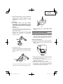
3. Installation (Fig. 4)
Insert the Hex bar wrench (8) into the hole of the
gear case and groove of the Cutter holder (9) in
order to lock the shaft.
Install cutting head on gear case of grass
trimmers. The mounting nut is left-hand-
threaded. Turn clockwise to loosen/counter-
clockwise to tighten.
8
9
Fig. 4
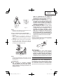
4. Adjusting line length
Set the engine speed as low as possible and tap
the head on the ground. The nylon line will be
drawn out about 1-3/16˝ (3 cm) with each tap.
(Fig. 5)
Fig. 5
Also, you can extend the nylon line by hand but
the engine must be completely stopped. (Fig. 6)
Fig. 6
Adjust the nylon line to the proper length
of 4-11/32˝–5-1/2˝ (11–14 cm) before each
operation.
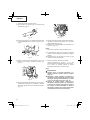
OPERATING PROCEDURES
Engine oil
○ Always use the specifi ed engine oil (multigrade
oil of classifi cation SAE 10W-30). Insuffi cient
engine oil or using engine oil other than the
specifi ed type may cause breakdown of the unit.
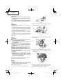
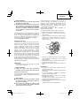
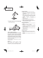
Filling up with engine oil
○ Place the unit horizontally on a clean, fl at surface.
○ Remove the oil cap and check whether the
engine oil comes up to the mouth of the oil tank
opening. (Fig. 7)
Fig. 7
○ If the oil level is low or when using the unit for the
fi rst time, fi ll the oil tank with engine oil up to the
mouth of the oil tank opening.
○ If the engine oil is conspicuously dirty or
discolored, change the oil.
○ Tighten the oil cap securely after fueling.
○ When using the unit for the fi rst time, change
the engine oil after running the engine for
approximately 10 hours. Subsequently, change
the oil after every 50 hours of operation.

10
English
CAUTION
● To avoid the risk of burn injury, allow the
engine to cool thoroughly before changing
the engine oil.
● To prevent breakdown, ensure that no sand
or dirt gets into the oil tank while refueling.
Fuel
WARNING
○ Provide good ventilation, when fueling or
handling fuel.
○ Fuel contains highly fl ammable and it is possible
to get the serious personal injury when inhaling
or spilling on your body. Always pay attention
when handling fuel. Always have good ventilation
when handling fuel inside building.
○ Always use branded 89 octane unleaded
gasoline.
○ Do not use a mixture of gasoline and engine
oil as this may lead to starter failure or power
reduction.
Fueling
WARNING
● Always shut off the engine and let it cool for
a few minutes before refueling.
Do not smoke or bring fl ames or sparks near
the fueling site.
● Slowly open the fuel tank, when fi lling up
with fuel, so that possible over-pressure
disappears.
● Tighten the fuel cap carefully, after fueling.
● Always move the trimmer at least 10 ft (3 m)
from the fueling area before starting.
● Always wash any spilled fuel from clothing
immediately with soap.
● Be sure to check for any fuel leakage after
refueling.
● Before fueling, in order to remove static
electricity from the main body, the fuel
container and the operator, please touch the
ground that is slightly damp.
Before fueling, clean the tank cap area carefully, to
ensure that no dirt falls into the tank.
Starting
CAUTION
Before starting, make sure the cutting
attachment does not touch anything.
1. Starting the cold engine
(1) Set ignition switch (10) to ON position. (Fig. 8)
10
Fig. 8
(2) Push priming bulb (11) several times so that fuel
fl ows through return pipe (12). (Fig. 9)
11
12
Fig. 9
(3) Set choke lever (13) to START position (closed)
(A). (Fig. 10)
13
START
RUN
Fig. 10
(4) Pull recoil starter briskly, taking care to keep the
handle in your grasp and not allowing it to snap
back. (Fig. 11)
Fig. 11
(5) When you hear the engine want to start, return
choke lever to RUN position (open) (B). (Fig. 10)
(6) Pull recoil starter briskly again. (Fig. 11)

11
English
NOTE
If engine does not start, repeat procedures from
2 to 5.
(7) Then allow the engine about 2–3 minutes to
warm up before subjecting it to any load.
(8) Check that the cutting attachment does not rotate
when the engine is idling.
2. Starting the warm engine
Use only 1, 6 and 8 of the starting procedure for a
cold engine.
If the engine does not start, use the same starting
procedure as for a cold engine.
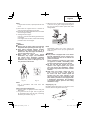
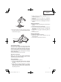
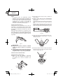
Cutting
WARNING
● Always wear the proper attire and protective
equipment when operating the unit. (Fig. 12)
● Keep others including children, animals,
bystanders and helpers outside the 15 m
hazard zone. Stop the engine immediately if
you are approached. (Fig. 13)
● When grass or vines wrap around
attachment, stop engine and attachment
and remove them. Continuing operation
with grass or vines wrapped around the
attachment may result in damages such as
early abrasion of the clutch.
Fig. 12 Fig. 13
NOTE
Use in accordance with local laws and
regulations.
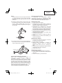
Using a semi-auto cutting head
○ Set the engine at high speed when using this
attachment.
○ Cut grass from left to right. The cut grass will
be discharged away from the body, minimizing
transfer to your clothes. (Fig. 14)
○ With nylon cord, use about 3/4” (2 cm) of the end
of the cord to cut grass. Using the full length of
the cord will reduce rotation speed and make
cutting diffi cult.
Fig. 14
NOTE
Automatically feeds more nylon cutting line
when it is tapped at low rpm (not greater than
6,000 min
-1
).
WARNING
● This product is equipped with a line limiter
that will automatically cut any excess cord.
When operating the unit, do not remove the
guard or line limiter.
As the resistance is greater for nylon cords
as opposed to blades, mishandling could
increase engine load and result in damage.
● Do not use with the engine set at low
speeds. If the engine speed is low, grass
may wrap around the attachment, causing
the clutch to slip which could result in clutch
abrasion.
● With nylon cord cutters, always use over
5-7/8” (15 cm) of cord. If the length of
the cord is too short, rotation speed will
increase and may cause damage to the
nylon cord cutter. As the curved drive shaft
tube model in particular is not equipped with
a deceleration mechanism, the possibility
of increased rotation speed for the cutting
attachment is high.
Stopping (Fig. 15)
Decrease engine speed and run at an idle for a few
minutes, then turn off ignition switch (10).
10
Fig. 15

12
English
WARNING
A cutting attachment can injure while it
continues to spin after the engine is stopped
or throttle trigger is released. When the
unit is turned off , make sure the cutting
attachment has stopped before the unit is
set down.
MAINTENANCE
MAINTENANCE, REPLACEMENT OR REPAIR
OF THE EMISSION CONTROL DEVICES AND
SYSTEMS MAY BE PERFORMED BY ANY NON-
ROAD ENGINE REPAIR ESTABLISHMENT OR
INDIVIDUAL.
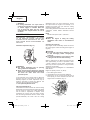
Carburetor adjustment (Fig. 16)
T
Fig. 16
WARNING
● The cutting attachment may be spinning
during carburetor adjustments.
● Never start the engine without the complete
clutch cover and tube assembled! Otherwise
the clutch can come loose and cause
personal injuries.
In the carburetor, fuel is mixed with air. When the
engine is test run at the factory, the carburetor is
basically adjusted. A further adjustment may be
required, according to climate and altitude. The
carburetor has one adjustment possibility:
T = Idle speed adjustment screw.
Idle speed adjustment (T)
Check that the air fi lter is clean. Be sure the cutting
attachment stop turning when the engine idle. When
the idle speed is correct, the cutting attachment
will not rotate. If adjustment is required, close
(clockwise) the T-screw, with the engine running,
until the cutting attachment starts to rotate. Open
(counter-clockwise) the screw until the cutting
attachment stops. You have reached the correct
idle speed when the engine runs smoothly in all
positions well below the rpm when the cutting
attachment starts to rotate.
If the cutting attachment still rotates after idle speed
adjustment, contact Hitachi Authorized Service
Centers.
NOTE
Standard Idle rpm is 2,800 – 3,200 min
–1
.
WARNING
When the engine is idling the cutting
attachment must under no circumstances
rotate.
Changing the engine oil
Dirty engine oil will considerably reduce the service
life of the engine. Check and change the engine oil
regularly.
CAUTION
● To avoid risk of burn injury, allow the engine
to cool thoroughly before changing the
engine oil.
● To prevent breakdown, ensure that no sand
or dirt gets into the tank while refueling.
When to change the oil: When fi rst using the unit,
after approximately 10 hours of operation or after
1 month, whichever occurs earlier; subsequently,
after every 50 hours of operation or every 6 months,
whichever occurs earlier.
Specifi ed engine oil: Multigrade oil of classifi cation
SAE 10W-30
Engine oil capacity: 4.88 cu. in. (80 ml)
1. Turn off the ignition switch.
2. Check that the fuel cap is securely tightened.
3. Remove the oil cap, tilt the unit so that the oil
tank opening is on the underside and drain the
engine oil into a container. (Fig. 17)
Fig. 17

13
English
4. When all the engine oil has been drained, place
the unit horizontally on a clean, fl at surface.
5. Fill the oil tank with engine oil up to the mouth of
the oil tank opening. (Fig. 7)
6. Tighten the oil cap securely by hand.
NOTE
○ Do not dispose of waste engine oil with garbage
or into the ground.
Dispose of the oil according to the specifi ed
method in your area.
If you are unsure, contact the retailer where the
oil was purchased.
○ Fill the oil tank with the specifi ed amount of
engine oil.
Too much or too little engine oil may result in
engine breakdown.
○ Engine oil deteriorates naturally even if unused.
Change the engine oil regularly.
Air fi lter (Fig. 18)
14
Fig. 18
The air fi lter must be cleaned from dust and dirt in
order to avoid:
○ Carburetor malfunctions.
○ Starting problems.
○ Engine power reduction.
○ Unnecessary wear on the engine parts.
○ Abnormal fuel consumption.
Clean the air fi lter daily or more often if working in
exceptionally dusty areas.
Cleaning the air fi lter
Remove the air fi lter cover and the fi lter (14). Rinse
it in gasoline. Check that the fi lter is dry before
reassembly. An air fi lter that has been used for some
time cannot be cleaned completely. Therefore,
it must regularly be replaced with a new one. A
damaged fi lter must always be replaced.
Fuel fi lter (Fig. 19)
Remove the fuel fi lter (15) from the fuel tank, and
replace it if it is dirty.
NOTE
A blocked fuel fi lter (15) can prevent the supply of
fuel and cause a rotation malfunction of the engine.
15
Fig. 19
Spark plug (Fig. 20)
.024˝
(0.6 mm)
Fig. 20
The spark plug condition is infl uenced by:
○ An incorrect carburetor setting.
○ A dirty air fi lter.
○ Hard running conditions (such as cold weather).
○ Too much engine oil
These factors cause deposits on the spark plug
electrodes, which may result in malfunction and
starting diffi culties. If the engine is low on power,
diffi cult to start or runs poorly at idling speed, always
check the spark plug fi rst. If the spark plug is dirty,
clean it and check the electrode gap. Readjust if
necessary. The correct gap is .024˝ (0.6 mm). The
spark plug should be replaced after about 100
operation hours or earlier if the electrodes are badly
eroded.
NOTE
In some areas, local law requires using a resistor
spark plug to suppress ignition signals. If this
machine was originally equipped with resistor
spark plug, use same type of spark plug for
replacement.

14
English
4˝ (10 cm)
16
Fig. 23
(4) Push each line into the stopper holes (17),
leaving the loose ends approx. 4˝ (10 cm) in
length. (Fig. 24)
17
4˝ (10 cm)
4˝ (10 cm)
Fig. 24
(5) Insert both loose ends of the line through the
cord guide (18) when placing the reel in the case.
(Fig. 25)
18
17
Fig. 25
NOTE
When placing a reel in the case, try to line up the
stopper holes (17) with the cord guide (18) for
easier line release later.
(6) Place the cover over the case so that the cap
locking tabs (19) on the cover meet the long
holes (20) on the case. Then push the case
securely until it clicks into place. (Fig. 26)
Gear case (Fig. 21)
Check gear case or angle gear for grease level
about every 50 hours of operation by removing the
grease fi ller plug on the side of gear case.
If no grease can be seen on the fl anks of the
gears, fi ll the gear case with quality lithium based
multipurpose grease up to 3/4. Do not completely fi ll
the gear case.
Fig. 21
CAUTION
● Make sure to remove any dirt or grit when
attaching the plug to its original position.
●
Before attempting inspection or maintenance
of the gear case, make sure the case has
cooled.
Semi-auto cutting head
Nylon line replacement
(1) Remove the case (6) by fi rmly pushing inward
the locking tabs with your thumbs as shown in
Fig. 22.
6
Fig. 22
(2) After removing the case, take out the reel and
discard the remaining line.
(3) Fold the new nylon line unevenly (approx. 10 cm)
in half as shown in picture.
Hook the U-shaped end of the nylon line into the
groove (16) on the center partition of the reel.
Wind both halves of the line on the reel in the
same direction, keeping each half of the line on
its own side of the partition. (Fig. 23)

15
English
20
19
Fig. 26
(7) The initial cutting line length should be approx.
4-11/32˝–5-1/2˝ (11–14 cm) and should be equal
on both sides. (Fig. 27)
4-11/32˝–5-1/2˝
(11-14 cm)
4-11/32˝–5-1/2˝
Fig. 27
For long-term storage
Drain all fuel from the fuel tank. Start and let engine
run until it stops. Repair any damage which has
resulted from use. Clean the unit with a clean rag, or
the use of high pressure air hose. Put a few drops
of two-cycle engine oil into the cylinder through the
spark plug hole, and spin the engine over several
times to distribute oil.
Cover the unit and store it in a dry area.
Maintenance schedule
Below you will fi nd some general maintenance
instructions. For further information please contact
Hitachi Authorized Service Centers.
Daily maintenance
○ Clean the exterior of the unit.
○ Check the cutting attachment guard for damage
or cracks. Change the guard in case of impacts
or cracks.
○ Check that the cutting attachment is properly
centred, sharp, and without cracks. An off -centre
cutting attachment induces heavy vibrations that
may damage the unit.
○ Check that the cutting attachment nut is
suffi ciently tightened.
○ Check that nuts and screws are suffi ciently
tightened.
○ Check the volume and condition of the engine oil.
○ Check that the unit is undamaged and free of
defects.
Weekly maintenance
○ Check the starter, especially the cord and return
spring.
○ Clean the exterior of the spark plug.
○ Remove the spark plug and check the electrode
gap. Adjust it to 0.024˝ (0.6 mm), or change the
spark plug.
○ Check that the angle gear is fi lled with grease up
to 3/4.
○ Clean the air fi lter.
Monthly maintenance
○ Rinse the fuel tank with gasoline.
○ Clean the exterior of the carburetor and the
space around it.
○ Clean the fan and the space around it.

16
English
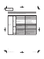
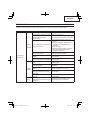
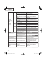
TROUBLESHOOTING
Use the inspections in the table below if the tool does not operate normally. If this does not remedy the
problem, consult your dealer or the Hitachi Authorized Service Center.
Condition Cause Remedy
Engine does
not start
Fuel
system
Fuel tank is empty or fuel level is
low
Fill the fuel tank with the correct fuel
Fuel tank contains old fuel (off ensive
odor)
Replace with new fuel
Too much fuel is absorbed and
spark plug is wet
1.
Disconnect the spark plug and allow
to dry
2. Pull the starter handle 5 or 6 times to
remove the surplus fuel
3. Attach the spark plug
4. Set the choke lever to RUN position
and pull the starter handle
Fuel fi lter is clogged with dirt Clean the fuel fi lter
Fuel pipe is bent or disconnected Ensure that the fuel fl ows smoothly
Carburetor malfunction
Contact Hitachi Authorized Service
Centers
Electrical
system
Stop switch lead has short-
circuited
Contact Hitachi Authorized Service
Centers
Spark plug is dirty Replace or clean the spark plug
Electrode gap is too big Adjust the gap to 0.6 mm
Poor connection between high
tension cable and spark plug
Reconnect
Electrical system malfunction
Contact Hitachi Authorized Service
Centers
Other
Muffl er exhaust port is clogged
with carbon
Contact Hitachi Authorized Service
Centers for repair

17
English
Condition Cause Remedy
Engine starts
but cuts out
straightaway
Engine is apt to
cut out
Fuel
system
Fuel tank is empty or fuel level is
low
Fill the fuel tank with the correct fuel
Fuel tank contains old fuel (off ensive
odor)
Replace with new fuel
Engine oil has not been added
Contact Hitachi Authorized Service
Centers
Choke lever is in START position Set the choke lever to RUN position
Air has got into fuel system Reconnect the fuel pipe or joint
Carburetor malfunction
Contact Hitachi Authorized Service
Centers
Electrical
system
Ignition failure
Spark plug failure Replace with new spark plug
Electrical system failure
Contact Hitachi Authorized Service
Centers
Other
Engine overheating
Wrong spark plug model
Replace with designated part
See “SPECIFICATIONS”
Dirty air cleaner Clean
Carbon clogging (muffl er exhaust
port)
Clean
Insuffi cient compression (piston,
piston ring, cylinder)
Contact Hitachi Authorized Service
Centers
Abnormal vibration
Cutting attachment is not properly
installed
See “Installation of cutting attachment”
Handle, handle bracket or other
fastening part is loose
Check and tighten
Grass is wrapped round gear case Remove grass
Engine is running but blade
does not move
Movement is poor
Grass is wrapped round gear case Remove grass and dirt
Engine does not stop Stop switch failure
Set the choke lever to START position
to stop the engine
Cease use immediately and contact
Hitachi Authorized Service Centers
Engine stops when throttle
is closed
Idle speed is too low
Contact Hitachi Authorized Service
Centers
Blade continues rotating
when throttle is closed
Idle speed is too high
Throttle wire is too taut
Contact Hitachi Authorized Service
Centers

18
Français
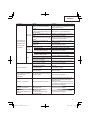
SIGNIFICATION DES SYMBOLES
REMARQUE:
Certains appareils n’en sont pas pourvus.
Symboles
ATTENTION
Les symboles suivants sont utilisés pour l’outil. Bien se familiariser avec leur
signifi cation avant d’utiliser l’outil.
Il est important que vous lisiez
et compreniez bien avant
utilisation et que vous respectiez
les précautions de sécurité
et avertissements suivants.
L’utilisation inattentive ou
inadéquate de cet appareil peut
provoquer des blessures graves
voire mortelles.
Utilisez des chaussures
antidérapantes et solides.
Etranglement – Position
marche (ouverte)
Etranglement – Position de
démarrage (fermé)
Lisez attentivement et respectez
toutes les instructions et tous les
avertissements donnés dans ce
manuel et sur le produit.
START
Marche/Allumer
Utilisez toujours des lunettes de
protection ainsi qu’un casque et
des protections d’oreilles lorsque
vous utilisez ce produit.
STOP
Arrêt/Eteindre
Maintenez les enfants,
spectateurs et aides à plus de
15 m de l’appareil. Si quelqu’un
s’approche de vous, coupez
immédiatemment le moteur et
arrêtez l’outil de coupe.
Remplissage de carburant
Remplissage d’huile moteur
Faites attention aux projections
d’objets.
Surface chaude – Tout
contact avec une surface
chaude peut provoquer de
graves brûlures.
min
-1
Indique la vitesse maximale de
l’arbre. N’utilisez pas d’outil de
coupe dont la vitesse de rotation
(nombre de tours/minute) est
inférieure à la vitesse de rotation
de l’arbre.
Indique l’emplacement
de la poignée. Flèches
pour indiquer les limites
concernant le positionnement
de la poignée.
Au besoin, utilisez des gants,
notamment lors du montage de
l’équipement de coupe.
Indique l’emplacement de
la protection de l’outil de
coupe pour un coupe-herbe
ou une tête de coupe semi-
automatique.
Avant l’utilisation de votre nouvelle machine
• Lisez attentivement le manuel d’utilisation.
• Vérifi ez que l’équipement de coupe est monté et réglé correctement.
• Démarrez la machine et vérifi ez le réglage du carburateur. Voir la section “ENTRETIEN”.

19
Français
15
16
17
18
Sommaire
DESCRIPTION .................................................... 19
PRÉCAUTIONS ET CONSIGNES DE SÉCURITÉ
... 20
GARANTIE .......................................................... 23
CARACTÉRISTIQUES ........................................ 23
MONTAGE .......................................................... 24
UTILISATION ....................................................... 26
ENTRETIEN ........................................................ 28
DÉPANNAGE ...................................................... 33
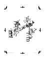
DESCRIPTION
Ce manuel étant commun à plusieurs modèles, vous
constaterez peut-être certaines diff érences entre
les images et votre appareil. Suivez les instructions
relatives à votre modèle.
1. Bouchon du réservoir de carburant
2. Commande des gaz
3. Poignée du lanceur
4. Protection de l’outil de coupe
5. Outil de coupe
6. Tube de transmission
7. Poignée
8. Interrupteur marche-arrêt
9. Bougie
10. Pompe d’amorçage
11. Levier d’étranglement
12. Moteur
13. Boîte de vitesse
14. Bouchon d’huile
15. Clé à douille multiple
16. Mode d’emploi
17. Lunettes
18. Clé de forme hexagonal
e
19. Couvercle du moteur
20. Tasse à mesurer l’huile à moteur
3
11
10
1
12
19
14
9
12
8
7
6
13
5
4
2
20

20
Français
ATTENTION
Les gaz d'échappement du moteur de ce produit
contiennent des substances chimiques connues
dans l'État de la Californie pour causer le cancer,
des malformations congénitales ou d'autres
anomalies reproductives.
PRÉCAUTIONS ET CONSIGNES
DE SÉCURITÉ
Faites particulièrement attention aux stipulations
introduites par les mots ci-dessous:
AVERTISSEMENT
Information de première importance pour éviter
des dommages corporels graves ou mortels.
ATTENTION
Information importante afi n d’éviter des
dommages corporels ou matériels.
REMARQUE
Information utile pour une utilisation et un
fonctionnement corrects de la machine.
Sécurité de l’utilisateur
○ Portez toujours une visière et des lunettes de
protection.
○ Les lunettes étanches de protection agréées
sont conformes à la norme ANSI Z87.1 aux États
Unis.
○ Portez toujours un pantalon épais, des
chaussures antidérapantes, des gants et
une chemise à manches longues. Évitez les
vêtements amples, les shorts, les sandales et
les pieds nus. Veillez à ce que vos cheveux ne
descendent pas au-dessous des épaules.
○ Utilisez cette machine uniquement si vous êtes
en pleine possession de vos moyens physiques.
Évitez strictement la consommation d’alcool, de
drogue ou de médicaments.
○ Ne laissez jamais un enfant ou une personne
inexpérimentée se servir de ces machines.
○
Portez un dispositif de protection auditive agréé (3).
L’exposition prolongée à des sons forts peut
entraîner une défi cience auditive permanente.
Restez vigilant à tout ce qui vous entoure. Restez
attentif dans l’éventualité où une personne située
à proximité vous signalerait un problème.
Retirez les équipements de sécurité immédiatement
après avoir coupé le moteur de l’outil.
○ Protégez-vous la tête.
○ Ne mettez jamais le moteur en marche dans un
environnement fermé, comme dans une pièce
ou à l’intérieur d’un bâtiment. L'inhalation de gaz
d’échappement au monoxyde de carbone peut
être mortelle.
○ Nettoyez les poignées de toute trace d’huile ou
de carburant.
○ N’approchez jamais les mains du guide-chaîne
et de la chaîne.
○ N’attrapez jamais et ne tenez jamais la machine
par l’extrémité du guide-chaîne.
○ Après l’arrêt de la machine, attendez l’arrêt
complet de l’outil de coupe avant de poser la
machine.
○ Lors d’une utilisation prolongée, veillez à
pratiquer des pauses régulières afi n d’éviter des
troubles éventuels provoqués par les vibrations.
○ Ne pas utiliser l’outil de nuit ou sous de
mauvaises conditions météorologiques lorsque
la visibilité est mauvaise. Et n’utilisez pas
l’appareil lorsqu’il pleut ou tout de suite après
une averse.
Travailler sur un sol glissant peut conduire à un
accident si vous perdez l’équilibre.
○ Ne démarrez pas le moteur s’il y a des matières
infl ammables telles que des feuilles sèches, de
vieux papiers ou du carburant dans les alentours.
○ Au besoin, utilisez des gants, lors du montage
ou du dégagement de l’outil de coupe. Le non-
respect de cette précaution peut provoquer des
blessures.
AVERTISSEMENT
●
Toujours utiliser l’outil avec un équipement de
protection et des vêtements. Le non-respect de
cette consigne pourrait entraîner des accidents
comme des brûlures ou des blessures.
● Ne touchez pas à la zone d’étincelle ou
à la zone de haute tension pendant le
fonctionnement. Cela peut entraîner un choc
électrique.
● Ne laissez pas les enfants près de l’outil
pendant le fonctionnement.
● Ne touchez pas au moteur, au capot du
moteur ou au conduit d’évacuation pendant
ou juste après l’utilisation. Cela peut
entraîner des brûlures ou des blessures.
●
Les systèmes anti-vibrations ne préviennent
pas de la maladie des doigts blancs, ni du
syndrome du canal carpien. Par conséquent,
en cas d’utilisation régulière et continue de
votre machine, surveillez soigneusement l’état
de vos mains et de vos doigts. Si l’un des
symptômes ci-dessus venait à apparaître, il
serait indispensable de vous faire examiner
immédiatement par votre médecin.
La page est en cours de chargement...
La page est en cours de chargement...
La page est en cours de chargement...
La page est en cours de chargement...
La page est en cours de chargement...
La page est en cours de chargement...
La page est en cours de chargement...
La page est en cours de chargement...
La page est en cours de chargement...
La page est en cours de chargement...
La page est en cours de chargement...
La page est en cours de chargement...
La page est en cours de chargement...
La page est en cours de chargement...
La page est en cours de chargement...
La page est en cours de chargement...
La page est en cours de chargement...
La page est en cours de chargement...
La page est en cours de chargement...
La page est en cours de chargement...
La page est en cours de chargement...
La page est en cours de chargement...
La page est en cours de chargement...
La page est en cours de chargement...
La page est en cours de chargement...
La page est en cours de chargement...
La page est en cours de chargement...
La page est en cours de chargement...
La page est en cours de chargement...
La page est en cours de chargement...
La page est en cours de chargement...
La page est en cours de chargement...
La page est en cours de chargement...
La page est en cours de chargement...
La page est en cours de chargement...
La page est en cours de chargement...
-
 1
1
-
 2
2
-
 3
3
-
 4
4
-
 5
5
-
 6
6
-
 7
7
-
 8
8
-
 9
9
-
 10
10
-
 11
11
-
 12
12
-
 13
13
-
 14
14
-
 15
15
-
 16
16
-
 17
17
-
 18
18
-
 19
19
-
 20
20
-
 21
21
-
 22
22
-
 23
23
-
 24
24
-
 25
25
-
 26
26
-
 27
27
-
 28
28
-
 29
29
-
 30
30
-
 31
31
-
 32
32
-
 33
33
-
 34
34
-
 35
35
-
 36
36
-
 37
37
-
 38
38
-
 39
39
-
 40
40
-
 41
41
-
 42
42
-
 43
43
-
 44
44
-
 45
45
-
 46
46
-
 47
47
-
 48
48
-
 49
49
-
 50
50
-
 51
51
-
 52
52
-
 53
53
-
 54
54
-
 55
55
-
 56
56


Hitachi CG 25EUAP Safety Instructions And Instruction Manual
- Catégorie
- Coupe-herbe
- Taper
- Safety Instructions And Instruction Manual
dans d''autres langues
- English: Hitachi CG 25EUAP
- español: Hitachi CG 25EUAP
Documents connexes
-
Hitachi CG23ECPSL Le manuel du propriétaire
-
-
-
-
-
-
-
-
Hitachi CG22EAS(S) Le manuel du propriétaire
-