
1
ORIGINAL
I
NSTRUCT
I
ONS
1
A GUIDE
TO
GOOD DRILLING
PRACTICE
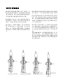
To get the best
possible performance
from your new
Magne�c
Drilling Machine
,
please read this
carefully
BEFORE using the
drill.
DE
NL
ES
HB350
Magne�c Drill
WARNING:
For your personal safety, READ and UNDERSTAND before using.
SAVE THESE INSTRUCTIONS FOR FUTURE REFERENCE.
FR
PT
CH
VN
FA
AR
INSTRUÇÕES ORIGINAIS
Ursprüngliche Anweisungen
Instruc�ons originales
Originele instruc�es
Instrucciones originales
HƯỚNG DẪN CƠ BẢN

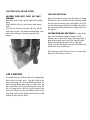
BEFORE YOU START
To help you get the best possible performance
from your new Magnetic Drilling Machine, this
guide contains simple, sensible pointers for the
safe, eective, and long-term use of the
equipment.
Please read it ca refully
before using
the
drill.
• Ensure that you have observed all the general
and speciety procedures.
Explanation
of the pictograms
on
the
specification plate
of the Makita
HB350
DANGER!
Indicates an imminent danger or risk to
life and health of a general nature.
ELECTRICAL
DANGER!
This means a direct pending danger or
risk to life due to electricity.
CAUTION!
Indicates a possible danger or risk of
slight injury or damage to property.
WEAR
EYE & EAR PROTECTORS
USE SAFETY
STRAP!
to aach the tool to the workpiece.
READ THE MANUAL
Read the manual before operang
the machine.
WEEE compliance cercate:- on request
All magnec drilling systems are fully compliant.
with RoHS regulans.
Due to the presence of hazardous components in the
equipment, used electrical and electronic equipment may
have a negave impact on the environment and human
health.
Do not dispose of electrical and electronic appliances with
household waste.
In accordance with the European Dircecve on waste
Electrical and electronic equipment should be collected
separately and delivered to a separate collecon point
for municipal waste, operang in accordance with the
environmental protecn regulaons.
this is indicated by the symbol of the crossed out
wheeled bin placed on the equipment.
CONTENTS
•
HB350 Specion
•
The Broach Cuing Concept
•
Intended Use
•
General Safety Instrucons
•
Material and Cuing speeds
•
Feeds and Speeds
•
Fitting Safety Guard & Strap and Oil
Bottle
•
Fitting Cuers
•
Panel Operaon
•
Motor diagram & parts list
•
Stand diagram & parts list
•
EC Declaraon

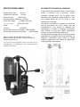
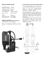
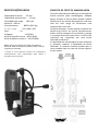
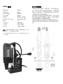
CUTTING TIME
CUTTING TIME
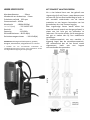
HB350
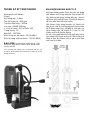
SPECIFIFCATION
Cutter capacity - 35mm
Chuck Capacity - 13mm
No load speed - 850 rpm
Power consumption - 1050w
Clamping
force -
8000N (
815
kg)
L
x H x W (mm) - 225 x 490 x
195
Weight
- 11.
Voltage - 110/230v
Sound pressure level - 89.13 dB(A)
Sound Power level - 100.12 dB(A)
I
NCLUDES
:
Integral c oo l a n t s y s tem ,
Warra nty
,
Carrying case, Allen keys, Safety
strap &
Guard
• Due to our continuing programme of research and
development, these specifications are subject to change
without notice.
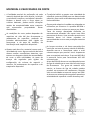
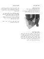
THE BROACH CUTTING CONCEPT
If you are unfamiliar with the use of annular
(or broaching) cutters, take a few minutes to
read this guide - you will benefit from the better
performance and longer life of the tool if you
understand the concept.
Annular c utters only c u t m arterial at the
periphery of the hole, rather than converting
the entire hole to shavings. As a result, the time
and energy required to make the hole is lower
than for a traditional twist drill.
The b r o ach hing c a p a c ity of a m ac hine i s
therefore, greater than the twist drill capacity.
The slug ejected after the cut also has a higher
scrap value than shavings.

Op�onal Accessories
For details of options, either refer to the catalog or inquire at the store of
purchase or a Makita sales office.
If you need any assistance for more details regarding these accessories, ask your local Makita
Service Center.
• HSS Cutter
• TCT Cutter
• Drill chuck
INTENDED USE
The intended use of this magnetic drill is to drill holes in ferrous metals. The magnet is used to hold
the drill in place whilst the drill is functioning. It is designed for use in fabrication, construction,
railways, petrochemical, and any other applications when drilling ferrous metal.
Any deviation from its intended use will not be covered by warranty.
GENRAL POWER TOOL SAFETY INSTRUCTIONS
General power tool safety warnings
WARNING Read all safety warnings, instructions, illustrations, and specifications provided with this
power tool. Failure to follow all instructions listed below may result in electric shock, fire and/or serious
injury.
Save all warnings and instructions for future reference.
The term "power tool" in the warnings refers to your mains-operated (corded) power tool or battery-
operated (cordless) power tool.
1) Work area safety
a) Keep work area clean and well lit. Cluttered or dark areas invite accidents.
b) Do not operate power tools in explosive atmospheres, such as in the presence of flammable liquids,
gases, or dust. Power tools create sparks which may ignite the dust or fumes.
c) Keep children and bystanders away while operating a power tool. Distractions can cause you to lose
control.
2) Electrical safety
a) Power tool plugs must match the outlet. Never modify the plug in any way. Do not use any
adapter plugs with earthed (grounded) power tools. Unmodified plugs and matching outlets will
reduce risk of electric shock.
b) Avoid body contact with earthed or grounded surfaces, such as pipes, radiators, ranges, and
refrigerators. There is an increased risk of electric shock if your body is earthed or grounded.
c) Do not expose power tools to rain or wet conditions. Water entering a power tool will increase the risk of
electric shock.
d) Do not abuse the cord. Never use the cord for carrying, pulling, or unplugging the power tool. Keep cord
away from heat, oil, sharp edges or moving parts. Damaged or entangled cords increase.
CAUTION: These accessories or as achments are recommended for use with
your Makita tool specified in this manual. The use of any other accessories or
attachments might present a risk of injury to persons. Only use accessory or
attachment for its stated purpose.

the risk of electric shock.
e) When opera�ng a power tool outdoors, use an extension cord suitable for outdoor use. Use of a cord
suitable for outdoor use reduces the risk of electric shock.
f) If opera�ng a power tool in a damp loca�on is unavoidable, use a residual current device (RCD)
protected supply. Use of an RCD reduces the risk of electric shock.
NOTE The term “residual current device (RCD)” can be replaced by the term “ground fault circuit
interrupter (GFCI)” or “earth leakage circuit breaker (ELCB)”.
3) Personal safety
a) Stay alert, watch what you are doing and use common sense when opera�ng a power tool. Do not use a
power tool while you are �red or under the influence of drugs, alcohol, or medica�on. A moment of
inatten�on while operating power tools may result in serious personal injury.
b) Use personal protective equipment. Always wear eye protec�on. Protective equipment such as a dust
mask, non-skid safety shoes, hard hat or hearing protection used for appropriate conditions will reduce
personal injuries.
c) Prevent uninten�onal starting. Ensure the switch is in the off position before connec�ng to power
source and/or battery pack, picking up or carrying the tool.
Carrying power tools with your finger on the switch or energizing power tools that have the switch on
invites accidents.
d) Remove any adjus�ng key or wrench before turning the power tool on. A wrench or a key left attached
to a rotating part of the power tool may result in personal injury.
e) Do not overreach. Always keep proper footing and balance. This enables better control of the power tool
in unexpected situations.
f) Dress properly. Do not wear loose clothing or jewelry. Keep your hair and clothing away.
from moving parts. Loose clothes, jewelry or long hair can be caught in moving parts.
g) If devices are provided for the connec�on of dust extrac�on and collec�on facili�es, ensure these are
connected and properly used. Use of dust collection can reduce dust-related hazards.
h) Do not let familiarity gained from frequent use of tools allow you to become complacent and ignore
tool safety principles. A careless action can cause severe injury within a fraction of a second.
4) Power tool use and care
a) Do not force the power tool. Use the correct power tool for your applica�on. The correct power
tool will do the job better and safer at the rate for which it was designed.
b) Do not use the power tool if the switch does not turn it on and off. Any power tool that cannot be
controlled with the switch is dangerous and must be repaired.
c) Disconnect the plug from the power source and/or remove the battery pack, if detachable, from
the power tool before making any adjustments, changing accessories, or storing power tools. Such
preven�ve safety measures reduce the risk of starting the power tool accidentally.
d) Store idle power tools out of the reach of children and do not allow persons unfamiliar with the
power tools or these instructions for power tools.
Power tools are dangerous in the hands of untrained users.
e) Maintain power tools and accessories. Check for misalignment or binding of moving parts,
breakage of parts and any other condition that may affect the power tool’s operation. If damaged,
have the power tool repaired before use.
Many accidents are caused by poorly maintained power tools.
f) Keep cutting tools sharp and clean. Properly maintained cutting tools with sharp cutting edges are less likely
to bind and are easier to control.
g) Use the power tool, accessories, and tool bits etc. in accordance with these instruc�ons, taking into
account the working condi�ons and the work to be performed. Use of the power tool for operations
different from those intended could result in a hazardous situation.
h) Keep handles and grasping surfaces dry, clean, and free from oil and grease.
Slippery handles and grasping surfaces do not allow for safe handling and control of the tool in unexpected
situations.
5) Service
a) Have your power tool serviced by a qualified repair person using only identical replacement parts. This
will ensure that the safety of the power tool is maintained.

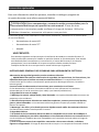
MAGNETIC DRILL SAFETY
INSTRUCTIONS
• Always inspect the whole unit before use.
• Regular maintenance is essential - check nuts,
screws etc. for tightness before each use.
• Check cable and plug for damage.
• Never use blunt or damaged cutters.
• Never use a larger diameter cutter than
specified for the machine.
• Always use the s a f e t y g ua r ds where
fitted and ensure they are operating correctly.
• Always wear goggles and gloves
• Remove rings, watches, ties etc. that could
tangle in the moving parts.
• Secure the unit with the safety strap before
drilling.
• The machine is for use on steel from 6 mm
thick with no air gap between the magnet core
and the workpiece. Curvature, paint, and
surface irregularities create an air gap. Keep
the air gap to a minimum.
• Keep the magnet and workpiece clean & free of
debris and swarf.
• Do not start the motor before ensuring that
the magnetic stand is clamped firmly to the
workpiece.
• Only use a general oil-based m e t a l cutting
oil.
• While drilling horizontally or overhead, use a
cutting paste or an appropriate coolant spray.
• Always disconnect from the power source
before cha n g i n g c u t t e r o r working on th e
machine.
• In the event of a jammed cutter, disconnect
from the power supply and free the jam before
reconnecting the tool.
• On swivel machines, ensure that the swivel
base is locked in the required position.
• Do not attempt to change speed while
the drill is running.
• Only use accessories recommended by the
manufacturer.
• Never lift or carry the unit by the power cord,
always use the handle.
• Never modify the tool in any way.
MAINTENANCE
INSTRUCTIONS
• Occasionally apply a few drops of oil to the
rack toothing.
• The bearings of the feed shaft are self-
lubricating and must not be greased
• Grease the sliding surface of the carriage
with MOLYCOTE grease.
• When not in use or being transported the
unit should be kept in the case supplied.
• After use ensure unit is clean of swarf and
dirt.
• Parts that are worn or damaged should be
r e p l a c e d immediately with g e n u i n e
manufacturer’s replacements.
• Ensure all cutting edges are sharp when in
operation. Using blunt cutting tools may lead
to an overload of the motor.
• Aft er e v e r y 30 m i n u t e s r u nn i n g, itis
recommended that the machine is laid on its
side to permit grease to run across the gear
train.
• After repeated use, the cradle may become
loose. This is remedied by adjusting the tension
screws on the side of the body. Put 2.5mm hex
wrench into head of cradle retaining nuts,
using 8mm Spanner undo the locking nuts anti-
clockwise, holding the hex wrench without
moving grub screws.
Using the hex wrench gently tighten screws in
series until the cradle moves freely in the slide
but does not allow the motor to wobble.
When a d j u s t m ent is c o m plete re -tighten
locking nuts clockwise, ensuring the grub
screws do not move from their new positions.
IMPORTANT!
– TO
PREVENT DAMAGE
TO THE
CIRCUITRY,
NEVER USE
ELECTROMAGNETIC DRILLING MACHINES
AND
WELDING EQUIPMENT
ON THE SAME W O R KP I E C E
SIMULTANEOUSLY.

6
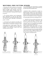
MATERIAL AND CUTTING
SPEEDS
• The ease with which material can be drilled
is dependent on several factors including
tensile strength and abrasion resistance.
Whilst hardness and/or strength is the usual
criterion, wide variations in machinability can
exist among material showing similar physical
properties.
• The cutting conditions can be dependent
upon requirements for tool life and surface
finish and further restricted by the rigidity of the
tool and work piece, lubrication, and machine
power available.
• The harder the material the lower the
cutting speed. Some materials of low hardness
contain abrasive constituents leading to rapid
cutting-edge wear at high speeds. Feed rates
are governed by rigidity of set up, volume of
material to be removed, surface finish and
available machine power.
• It is preferable to set and maintain a constant
surface speed (RPM) for a given material and vary
the feed rate within defined limits.
• Machine feed is measured in inches or
millimeters per minute and is the product of
RPM x number of teeth in the cutter x feed per
tooth. Too light or excessively high feed rates
will both cause premature cutter failure. Heavy
feeds on hard materials will cause chipping of
the cutting edge and excessive heat generation.
• Slender and lo ng shank e d cutters are
restricted in feed rate due to deflection, and
wherever possible the largest and most robust
tool must be used. This is important for harder
materials. Steel up to 400 HB is the potential
limit for conventional M2 HSS tools.
Above 300 HB, cobalt alloy cutters should be
considered for increased tool life. In softer
grades of material, cobalt alloy cutters may give
increased output by increasing speeds and feed
rates by up to 50%. Tungsten Carbide cutters
permit surface speeds and feed rates up to

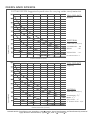
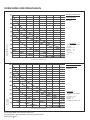
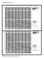
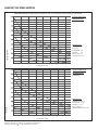
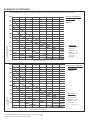
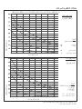
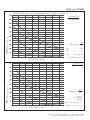
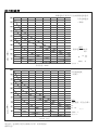
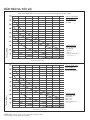
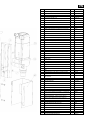
FEEDS AND SPEEDS
CUTTING SPEEDS
Suggested speed rates for varying cutter sizes/materials
TOOL FEED RATE
(Metric)
MATERIAL
Feed rate (mm/min)
Cutter Diameter (mm)
Cutter Diameter (inches)
ALUMINIUM - 60
BRASS - 45
MILD STEEL - 24
HI TENSILE STEEL - 9
TOOL FEED RATE
(Imperial)
MATERIAL
Feed rate
(inches/min)
MILD STEEL - 1”
PLEASE NOTE
:
These figures are quoted as a star ng point. Actual performance will be dictated by material
type, thickness and hardness, applica on, and cu er condi on.
Speed (RPM)
Speed (RPM)
10 706050403020 80
3/8” 3/4” 1.3/16” 1.9/16” 2” 2.3/8” 2.3/4” 3.1/8”
BRASS - 1 3/4
”
ALUMINIUM - 23/8
”
HI TENSILE STEEL - 3/8”

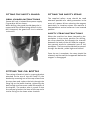
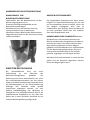
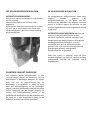
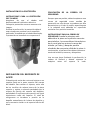
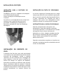
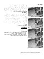
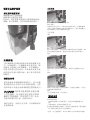
FITTING THE SAFETY GUARD
DRILL GUARD INSTRUCTIONS
Ensure drill unit is isolated from power supply.
Fit guard to drill as shown.
When drilling, the guard should always be in
contact with the surface being drilled. As the
drill is lowered, the guard will rise in relation.
to the drill.
FITTING THE OIL
BOTTLE
The cutting oil bottle is held in a sprung bracket
attached to the top of the drill body. Fit the
bracket by removing one of the cap screws from
the top plate and replace the bolt through the
fixing lug on the bottle bracket, tightening the
bolt enough to allow some radial movement of
the bracket. The coolant tube is a push fit into
the self-seal gland at the base of the tap and a
similar fitting on the lower arbor bracket.
FITTING THE SAFETY STRAP
The supplied safety strap should be used
wherever possible as a safety precaution in the
event of a power failure releasing the magnet;
particularly in situations where the machine is
clamped onto a vertical surface or in an inverted
position.
SAFETY STRAP INSTRUCTIONS
When the machine has been clamped to the
workpiece in the correct position for drilling,
the strap should be fed through the channel
between the body of the drill and the magnet,
then passed around a substantial part of the
workpiece. The free end should then be passed
through the buckle, pulled tight and locked.
Once the cut is complete, the strap should be
released, and the machine supported before the
magnet is disengaged.

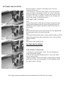
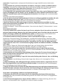
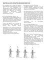
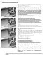
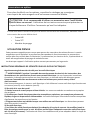
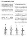
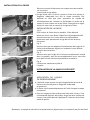
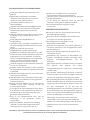
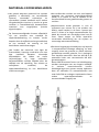
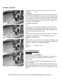
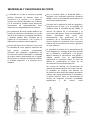
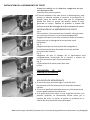
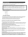
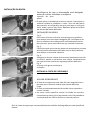
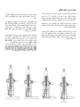
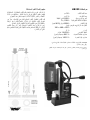
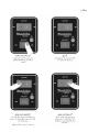
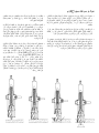
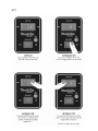
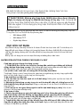
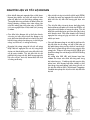
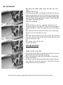
FITTING THE CUTTER
Fig. 1
Fig. 2
Fig. 3
Fig. 4
E
nsure power
is off before
working
on the machine
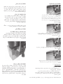
Insertion of pilot pin
• The pilot pin is used to both center the cutter and to
eject the slug on completion of the cut. It has a flat side.
to allow coolant to run down to reach the center of the
cut where the heat is greatest. Slide the pin through the
hole in the center of the cutter shank
.
FITTING THE CUTTER
Fig 1.
To insert the cutter in the arbor, first loosen the grub screws,
using an M5 hexagonal wrench. Ensure the grub screws are
sufficiently loose enough to allow the shank of the cutter to
enter freely.
Fig 2.
Ensure the drive flats on the cutter shank are fully aligned with
the two grub screws in the machine arbor.
Fig 3.
Ensuring the shank of the cutter is fully inserted inside the arbor,
tighten the grub screws fully to give the cutter a secure fitting
inside the arbor.
Fig 4.
The cutter is now ready for use.
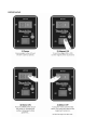
FIT THE SAFTY STRAP
APPLYING COOLANT
• Cutting oil ensures longer cutter life and enables the
slug to be ejected cleanly.
• Oil will be automatically delivered to the cutter when
the cut commences
• When cutting on vertical surfaces or upside down, cutting
paste, gel or foam is recommended. It is best applied inside
the cutter before drilling.
N.B. Safety strap and guards have been omitted from the photo’s for c
l
ar
i
ty.

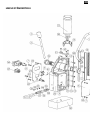
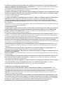
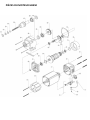
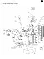
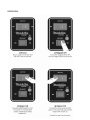
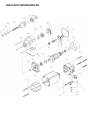
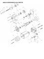
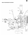
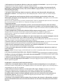
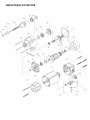
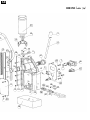
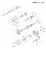
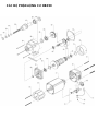
OPERATION
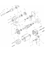
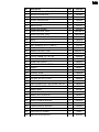
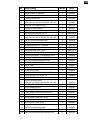
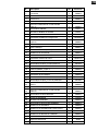
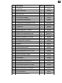
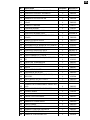
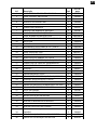
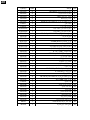
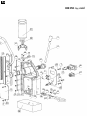
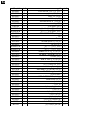
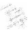
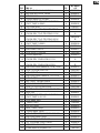
B350 MOTOR PARTS


EN
Nr.
Description
Qty
Part No
1
CARBON BRUSH ASSY. 6.3X10X18
2
EBD002
2
BRUSH HOLDER ASSY.
2
EBD001
3
SCREW M4 X 12
2
EBD003
4
SPRING WASHER M4
2
EBD004
5
PHILIPS HEAD SELF-TAP SCREW 4.8X45
4
EBD005
6
BACK COVER
1
EIB527
7
FIELD COIL CASING
1
EIB526
8
FIELD COIL ASSY 110V
1
EBD008-A
FIELD COIL ASSY 230V
1
EBD008-B
9
PHILIPS HEAD SELF - TAP SCREW 3.9X60
2
EBD009
10
BAFFE
1
EBD010
11
O RING
1
EBD011
12
BALL BEARING (8-22-7) 608 2Z
3
UDC022
13
DUST WASHER
1
EBD012
14
ARMATURE ASSY 110V
1
EBD013-A
ARMATURE ASSY 230V
1
EBD013-B
15
CIRCLIP 28MM X 1.2 B TYPE
1
EBD014
16
BALL BEARING (12-28-8) 6001 2Z
1
UDC023
17
GEAR CASE COVER
1
EBD015
18
CIRCLIP 10MM X 1 A TYPE
1
EBD016
19
GASKET
1
EBD017
20
INTER SHAFT ASSY.
1
EBD018
21
SPINDLE GEAR
1
EBD019
22
BALL BEARING (17-35-10) 6003 2RS
1
UDC004
23
OIL SEAL 20-30-7 B TYPE
2
EBD020
24
GEAR CASE
1
EBD021
25
PHILIPS HEAD SELF-TAP SCREW 4.8 X 60
4
EBD022
26
BALL BEARING 6904 2RS
1
EBD025
27
ARBOR BODY.
1
EIB528
28
ARBOR SPRING
1
EBD026
29
ARBOR EJECTION PLUG
1
EBD027
30
ARBOR WASHER
1
EBD028
31
ARBOR RUBBER WASHER
1
EBD029
32
ARBOR CIRCLIP
1
EBD030
33
CARBON BRUSH WASHER
2
EBD031
34
CARBON BRUSH FIXING SCREW
2
EBD032
35
PG9 PUSH FIT GLAND
1
40025
36
MOTOR LOCATING KEY
1
M1019

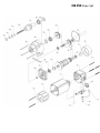
EN
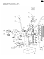
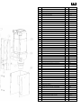
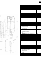
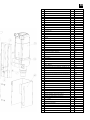
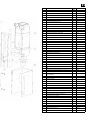
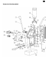
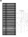
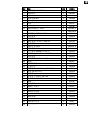
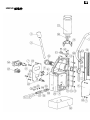
HB350 STAND PARTS

EN
Nr.
Description
Qty
Part No
1
CONDUIT (large dia 12mm) - PMA-PCLT-10B.50
1
M0443
2
M6 X 16 CAP HEAD SCREW
3
SC616CAP
3
SLIDE HB350 MAKITA
1
M1000
4
M6 X 25 CAP HEAD SCREW
7
SC625CAP
5
HANDLE KNOB (10mm KNOCK ON)
3
M0841
6
10MM X 130MM HANDLE (SMALL)
3
BD043
7
M4 X 6 BUTTON HEAD SCREW
8
SC46BUT
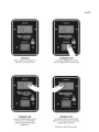
8
WARNING PLATE MAKITA HB350 CE JAPAN
CE JAPANMAKITA HB350 CE JAPAN
MAKITA HB350 CE JAPAN
M1002
WARNING PLATE MAKITA HB350 CE BELGIUM
BELGIUM
M1003
WARNING PLATE MAKITA HB350 CSA JAPAN
M1014
WARNING PLATE MAKITA HB350 UKCA UK
M1018
WARNING PLATE MAKITA HB350 RCM AUSTRALIA
M1021
9
25A - BRIDGE RECTIFIER (395-4310)
1
M0401
10
M5 X 16 CAP HEAD SCREW
3
SC516CAP
11
OILFEED TOP BRACKET - (MB30 BODY)
1
M0811A
12
BRASS RAIL (MB30)
2
M0101
13
RACK (MB30)
1
M0831
14
OIL CUP RETAINING CLIP COMPLETE
1
10076C
15
M5 NYLOC
6
10085B
16
M5X25 KNURLED POINT GRUB SCREW
5
10085A
17
CAPACITOR
1
RD43118
18
BUSH (PINION) - 33 X 28 X 20 OILITE BUSH
2
M0081
19
PINION END CAP - DEEP
1
M0072
20
O CLIP 8-11 BOCLIP8/11
1
RD47179
21
D5000 OIL CUP ASSEMBLY
1
30046A
22
U-06040(30MC) 6MM X 4MM CLEAR POLYURETHANE TUBE
1
BD029
23
MAKITA HB350 CONTROL PANEL PLATE
1
M1001
24
M16 PUSH FIT GLAND - PMA BVND-M160GT
1
40026
25
MB30 BODY BLACK
1
M0001BLK
26
M16 PIGTAIL GLAND COMPLETE WITH LOCK NUT - BBSM 16
1
10231
27 USA CABLE - 14 GAUGE - 3M - AB-CAB-870
C
ABL03
EUROPEAN CABLE C/W MOULD PLUG - AB-CAB-876 - 3M
C
ABL04
MAKITA BRAZIL CABLE C/W PLUG 220V - 3M
C
ABL05
3MTR-110V MAINS LEAD BLACK C/W IND PLUG
C
ABL06
ARGENTINA CABLE C/W PLUG - 230V - 3M
C
ABL08
AUS/NZ-3M MAINS CABLE C/W MOULDED PLUG-AB-CAB-866
CABL09
28
M8 WASHER FOR ARBOR INTERNAL
1
RD47187
29
M4 BRASS NUT
1
NUT-M4-B
30
HB350 MAGNET BASE
1
M1020
31
M4 X 6 SLOTTED CSK MC SCREW - BZP
5
SC46CSK
32
M4 X 12 CSK MC SCREW - BRASS
1
SC412CSK-B
33
M4 SHAKE PROOF WASHER-BZP-WSH-227-004-ZC221
9
SPWR-M4
34
PINION - (SMALL)
1
M0041
35
EIBENSTOCK BHM35 DRILL UNIT - 110V MAKITA BLUE
EIB522
EIBENSTOCK BHM35 DRILL UNIT - 230V MAKITA BLUE
EIB523
36
DRILL STOP/START SWITCH - 110V - KJD17F/120V/50HZ -
KJD17-P2-F2-V1-M2-A1
NCP001
DRILL STOP/START SWITCH - 230V - KJD17F-230V-50HZ-
KJD17F-P2-F2-V3-M2-A1
NCP002
37
MAGNET SWITCH - NCP PANEL - B418CG00000
1
NCP006
38
G.F.S. (MB30)
1
M0441
39
1/8 BSP-6MM BLACK PUSH FIT
1
50015
40
GUARD TO SUIT NEW UNI 1 MBQ35N/EQ35N/EBM35
1
VISO18
41
318-565 VARISTOR (V150LA10A)
W18XC522
VARISTOR HIGHSURGE 20MM 275 VRMS
W18XC521
42
248-447 FUSE HOLDER
1
W18XC511
43
2A FUSE (RAPID 26-2469)
1
W18XC512
44
WASHER SMBK1869836HPU
1
UOD009

EN
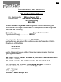
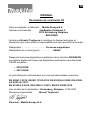
ORIGINAL
EC Declaration of Conformity
We as the manufacturers Makita Europe N.V.
Business address Jan-Baptist Vinkstraat 2
3070 Kortenberg
BELGIUM
Authorize Hiroshi Tsujimura for the compilation of the technical file and
declare under our sole responsibility that the product(s);
Designation …………………............ Magnetic Drill
Designation of Type(s) …………….. HB350
Fulfills all the relevant provisions of 2006/42/EC
and also fulfills all the relevant provisions of the following EC/EU
Directives:
− 2014/30/EU
− 2011/65/EU
and are manufactured in accordance with the following Harmonised
Standards:
EN 62841-1:2015, EN ISO 12100:2010, EN 61000-6-2:2005, EN 61000-
6-4:2007+A1:2011,
EN 61000-3-2:2014, EN 61000-3-3:2013, EN IEC 63000:2018
Place and date of declaration: Kortenberg, Belgium, 12.2.2021
Responsible person: Hiroshi Tsujimura
Director - Makita Europe N.V.

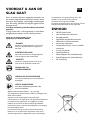
BEVOR SIE
BEGINNEN
Dieser Leitfaden enthält einfache, praktische
Hinweise für einen sicheren, effektiven Betrieb
über eine lange Lebensdauer und die
bestmögliche Leistung Ihrer neuen
Magnetbohrmaschine.
Bie lesen Sie diesen Leiaden vor dem
Gebrauch der Bohrmaschine sorgfälg.
• Sicherstellen, dass alle allgemeinen und
speziellen Sicherheitsvorkehrungen eingehalten
werden.
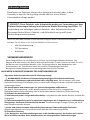
Erklärung der Piktogramme auf dem
Typenschild der Makita HB350
GEFAHR!
Weist auf eine unmittelbare
Lebensgefahr oder eine Gefährdung
Ihrer Gesundheit von allgemeiner Natur
hin.
ELEKTRISCHER SCHLAG!
Weist auf eine direkte Lebensgefahr
oder ein Risiko durch elektrische Schläge
hin.
VORSICHT!
Weist auf eine mögliche Gefahr oder ein
Risiko von leichten Verletzungen oder
Sachschäden hin.
SCHUTZBRILLE UND GEHÖRSCHUTZ
TRAGEN
SPANNGURT BENUTZEN!
Der Spanngurt dient zum Befestigen des
Werkzeuges am Werkstück.
BEDIENUNGSANLEITUNG LESEN
Vor Gebrauch der Maschine die
Bedienungsanleitung lesen.
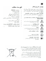
WEEE-Konformitätsbescheinigung: auf Anfrage erhältlich.
Alle Magnetbohrsysteme sind vollständig mit den RoHS-
Richtlinien konform.
Elektro- und Elektronik-Altgeräte können schädliche
Auswirkungen auf die Umwelt und die Gesundheit haben,
weil sie Gefahrenstoffen enthalten.
Elektro- und Elektronikgeräte dürfen nicht im
Haushaltsmüll entsorgt werden.
Gemäß der europäischen Verordnung über
Elektro- und Elektronik-Altgeräte
müssen diese in Übereinstimmung mit den
Umweltschutzbestimmungen separat gesammelt
und an eine separate kommunale
Abfallentsorgungsstelle geliefert werden.
Dies wird durch das Symbol mit der
durchgestrichenen Mülltonne auf dem Gerät
angegeben.
INHALT
•
HB350 – Technische Daten
•
Das Konzept des Räumschneidens
•
Verwendungszweck
•
Allgemeine Sicherheitshinweise
•
Material und
Schnittgeschwindigkeiten
•
Vorschübe und Drehzahlen
•
Befestigen des Spanngurtes und
Einsetzen der Ölflasche
•
Einsetzen des Schneidwerkzeuges
•
Bedienkonsole
•
Motorzeichnung & Teileliste
•
Ständerzeichnung & Teileliste
•
EG-Konformitätserklärung
DE

SCHNITTZEIT
SCHNITTZEIT
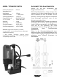
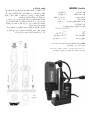
HB350 – TECHNISCHE DATEN
Bohrerdurchmesser – 35 mm
Spannbereich d.
Bohrfutters – 13 mm
Leerlaufdrehzahl – 850 U/min
Leistungsaufnahme – 1050 W
Magnethaltekraft – 8.000N (815 kg)
L x H x B (mm) – 225 x 490 x 195
Gewicht – 11 kg
Spannung – 110/230 V
Schalldruckpegel – 89,13 dB(A)
Schallleistungspegel – 100,12 dB(A)
INKLUSIVE: Integriertes Kühlsystem, Garantie,
Transportkoffer, Innensechskantschlüssel, Spanngurt
und Schutzvorrichtung
• Diese Angaben unterliegen aufgrund unseres
kontinuierlichen Forschungs- und Entwicklungsprogramm
unangekündigten Änderungen.
DAS KONZEPT DES RÄUMSCHNEIDENS
Sollten Sie mit der Anwendung von
Ringschneidemaschinen (oder
Räumschneidemaschinen) nicht vertraut sein,
nehmen Sie sich bitte einige Minuten Zeit, um
diesen Leitfaden zu lesen. Sie werden von der
besseren Leistung und der längeren Haltbarkeit
Ihres Werkzeuges profitieren, wenn Sie das
Konzept verstanden haben.
Ringschneidemaschinen schneiden nur Material
am Umfang des Lochs aus, anstatt das gesamte
Loch in Späne zu verwandeln. Als Folge davon,
sind die für die Erstellung des Lochs
erforderliche Zeit und Energie geringer als bei
Verwendung eines herkömmlichen
Spiralbohrers.
Daher ist die Räumschneidekapazität einer
Maschine größer als die Spiralbohrkapazität. Der
nach dem Bohrvorgang ausgeworfene Kern hat
außerdem einen höheren Schrottwert als
Metallspäne.

Optionales Zubehör
Einzelheiten zu Optionen können dem Katalog entnommen oder in dem
Geschäft, in dem der Kauf getätigt wurde oder bei einem Makita
Vertriebsbüro erfragt werden.
Wenn Sie Hilfe oder weitere Informationen bezüglich dieser Zubehörteile benötigen,
wenden Sie sich bitte an Ihr örtliches Makita Servicezentrum.
• HSS-Schneidwerkzeug
• TCT-Kernbohrer
• Bohrfutter
VERWENDUNGSZWECK
Dieser Magnetbohrer ist zum Bohren von Löchern in eisenhaltigen Metallen bestimmt. Der
Magnet wird dazu benutzt, den Bohrer während des Betriebs in seiner Position zu halten. Er ist für
das Bohren von eisenhaltigen Metallen in der Fertigungsindustrie, dem Baugewerbe, dem
Schienensektor, der Petrochemie sowie allen anderen Anwendungen bestimmt.
Bei jeglichen Abweichungen vom Verwendungszweck erlischt die Garantie.
ALLGEMEINE SICHERHEITSHINWEISE FÜR ELEKTROWERKZEUGE
Allgemeine Sicherheitswarnhinweise für Elektrowerkzeuge
WARNHINWEIS Alle diesem Elektrowerkzeug beigefügten Sicherheitswarnhinweise,
Anweisungen, Abbildungen und technischen Daten sorgfältig lesen. Das Versäumnis, alle unten
stehenden Anweisungen zu befolgen, kann zu elektrischen Schlägen, Bränden und/oder schweren
Verletzungen führen.
Alle Warnhinweise und Anweisungen zur späteren Bezugnahme aufbewahren.
Der Begriff „Elektrowerkzeug“ in den Warnhinweisen bezieht sich auf Ihr netzgespeistes
(kabelgebundenes) Elektrowerkzeug oder Ihr batteriebetriebenes (kabelloses) Elektrowerkzeug.
1) Sicherheit im Arbeitsbereich
a) Arbeitsbereich sauber und gut beleuchtet halten. Unordentliche oder dunkle Bereiche erhöhen die
Unfallgefahr.
b) Elektrowerkzeuge dürfen nicht in explosiven Umgebungen wie in Gegenwart von entflammbaren
Flüssigkeiten, Gasen oder Stäuben benutzt werden. Elektrowerkzeuge erzeugen Funken, die Staub
oder Dämpfe entzünden können.
c) Kinder und andere Personen während des Gebrauchs des Elektrowerkzeuges fernhalten.
Ablenkungen können zum Verlust der Kontrolle über das Elektrowerkzeug führen.
2) Elektrische Sicherheit
a) Der Netzstecker des Elektrowerkzeuges muss in die Steckdose passen. Der Stecker darf in keiner
Weise modifiziert werden. Keine Adapterstecker mit schutzgeerdeten Elektrowerkzeugen
VORSICHT: Diese Zubehör- oder Aufsatzteile werden zur Verwendung mit dem
in dieser Bedienungsanleitung beschriebenen Makita Werkzeug empfohlen. Die
Verwendung von beliebigen anderen Zubehör- oder Aufsatzteilen kann zu
Personenschäden führen. Zubehör- und Aufsatzteile nur gemäß ihrem
Verwendungszweck einsetzen.

verwenden. Originalstecker und passende Steckdosen verringern das Risiko eines elektrischen
Schlages.
b) Körperkontakt mit geerdeten Oberflächen wie Rohren, Heizungen, Herden und Kühlschränken
vermeiden. Es besteht ein erhöhtes Risiko durch elektrischen Schlag, wenn Ihr Körper geerdet ist.
c) Elektrowerkzeug von Regen oder Nässe fernhalten. Das Eindringen von Wasser in ein
Elektrowerkzeug erhöht das Risiko eines elektrischen Schlages.
d) Das Kabel darf nicht zweckentfremdet werden. Benutzen Sie es nicht, um das Elektrowerkzeug zu
tragen, aufzuhängen oder den Stecker aus der Steckdose zu ziehen. Halten Sie das Kabel fern von
Hitze, Öl, scharfen Kanten, oder sich bewegenden Geräteteilen. Beschädigte oder verwickelte Kabel
erhöhen
das Risiko eines elektrischen Schlages.
e) Bei der Arbeit mit einem Elektrowerkzeug im Freien nur Verlängerungskabel verwenden, die auch
für den Außenbereich geeignet sind. Die Anwendung eines für den Außenbereich geeigneten
Verlängerungskabels verringert das Risiko eines elektrischen Schlages.
f) Wenn der Betrieb des Elektrowerkzeuges in feuchter Umgebung nicht vermeidbar ist, einen
Fehlerstromschutzschalter verwenden. Der Einsatz eines Fehlerstromschutzschalters vermindert das
Risiko eines elektrischen Schlages.
HINWEIS Der Begriff „ Fehlerstromschutzschalter“ kann durch den Begriff „FI-Schutzschalter“ ersetzt
werden.
3) Persönliche Sicherheit
a) Seien Sie aufmerksam, achten Sie darauf, was Sie tun, und gehen Sie mit Vernunft an die Arbeit
mit dem Elektrowerkzeug. Benutzen Sie kein Elektrowerkzeug, wenn Sie müde sind oder unter dem
Einfluss von Drogen, Alkohol oder Medikamenten stehen. Ein Moment der Unachtsamkeit beim
Gebrauch eines Elektrowerkzeuges kann zu ernsthaften Verletzungen führen.
b) Persönliche Schutzausrüstung verwenden. Immer eine Schutzbrille tragen. Das Tragen
persönlicher Schutzausrüstung, wie Staubmaske, rutschfeste Sicherheitsschuhe, Schutzhelm oder
Gehörschutz, je nach Art und Einsatz des Elektrowerkzeuges, verringert das Risiko von Verletzungen.
c) Unbeabsichtigte Inbetriebnahme vermeiden. Vergewissern Sie sich, dass das Elektrowerkzeug
ausgeschaltet ist, bevor Sie es an die Stromversorgung und/oder den Akku anschließen, es anheben
oder tragen.
Wenn Sie beim Tragen des Elektrowerkzeuges den Finger am Schalter haben oder das Gerät
eingeschaltet an die Stromversorgung anschließen, kann dies zu Unfällen führen.
d) Entfernen Sie Einstellwerkzeuge oder Schraubenschlüssel, bevor Sie das Elektrowerkzeug
einschalten. Ein Werkzeug oder Schlüssel, die sich in einem drehenden Teil des Elektrowerkzeuges
befinden, können zu Verletzungen führen.
e) Beim Arbeiten auf eine normale Körperhaltung achten. Sorgen Sie für einen sicheren Stand und
halten Sie jederzeit das Gleichgewicht. Dadurch können Sie das Elektrowerkzeug in unerwarteten
Situationen besser kontrollieren.
f) Tragen Sie geeignete Kleidung. Tragen Sie keine weite Kleidung oder Schmuck. Haar und Kleidung
von beweglichen
Teilen fernhalten. Lose Kleidung, Schmuck oder langes Haar können sich in beweglichen Teilen
verfangen.
g) Wenn Staubabsaug- und -auffangeinrichtungen montiert werden können, vergewissern Sie sich,
dass diese angeschlossen sind und richtig verwendet werden. Verwendung einer Staubabsaugung
kann Gefährdungen durch Staub verringern.
h) Wiegen Sie sich durch Vertrautheit mit dem Elektrowerkzeug nach vielfachem Gebrauch nicht in
falscher Sicherheit und setzen Sie sich nicht über die Sicherheitsregeln für Elektrowerkzeuge hinweg.
Achtloses Handeln kann binnen Sekundenbruchteilen zu schweren Verletzungen führen.
4) Korrekter und sorgfältiger Gebrauch von Elektrowerkzeugen
a) Überlasten Sie das Gerät nicht. Immer das für Ihre Anwendung bestimmte Elektrowerkzeug
verwenden. Mit dem passenden Elektrowerkzeug arbeiten Sie besser und sicherer im angegebenen
Leistungsbereich.
b) Kein Elektrowerkzeug benutzen, dessen Schalter defekt ist. Ein Elektrowerkzeug, das sich nicht
mehr ein- und ausschalten lässt, ist gefährlich und muss repariert werden.
La page est en cours de chargement...
La page est en cours de chargement...
La page est en cours de chargement...
La page est en cours de chargement...
La page est en cours de chargement...
La page est en cours de chargement...
La page est en cours de chargement...
La page est en cours de chargement...
La page est en cours de chargement...
La page est en cours de chargement...
La page est en cours de chargement...
La page est en cours de chargement...
La page est en cours de chargement...
La page est en cours de chargement...
La page est en cours de chargement...
La page est en cours de chargement...
La page est en cours de chargement...
La page est en cours de chargement...
La page est en cours de chargement...
La page est en cours de chargement...
La page est en cours de chargement...
La page est en cours de chargement...
La page est en cours de chargement...
La page est en cours de chargement...
La page est en cours de chargement...
La page est en cours de chargement...
La page est en cours de chargement...
La page est en cours de chargement...
La page est en cours de chargement...
La page est en cours de chargement...
La page est en cours de chargement...
La page est en cours de chargement...
La page est en cours de chargement...
La page est en cours de chargement...
La page est en cours de chargement...
La page est en cours de chargement...
La page est en cours de chargement...
La page est en cours de chargement...
La page est en cours de chargement...
La page est en cours de chargement...
La page est en cours de chargement...
La page est en cours de chargement...
La page est en cours de chargement...
La page est en cours de chargement...
La page est en cours de chargement...
La page est en cours de chargement...
La page est en cours de chargement...
La page est en cours de chargement...
La page est en cours de chargement...
La page est en cours de chargement...
La page est en cours de chargement...
La page est en cours de chargement...
La page est en cours de chargement...
La page est en cours de chargement...
La page est en cours de chargement...
La page est en cours de chargement...
La page est en cours de chargement...
La page est en cours de chargement...
La page est en cours de chargement...
La page est en cours de chargement...
La page est en cours de chargement...
La page est en cours de chargement...
La page est en cours de chargement...
La page est en cours de chargement...
La page est en cours de chargement...
La page est en cours de chargement...
La page est en cours de chargement...
La page est en cours de chargement...
La page est en cours de chargement...
La page est en cours de chargement...
La page est en cours de chargement...
La page est en cours de chargement...
La page est en cours de chargement...
La page est en cours de chargement...
La page est en cours de chargement...
La page est en cours de chargement...
La page est en cours de chargement...
La page est en cours de chargement...
La page est en cours de chargement...
La page est en cours de chargement...
La page est en cours de chargement...
La page est en cours de chargement...
La page est en cours de chargement...
La page est en cours de chargement...
La page est en cours de chargement...
La page est en cours de chargement...
La page est en cours de chargement...
La page est en cours de chargement...
La page est en cours de chargement...
La page est en cours de chargement...
La page est en cours de chargement...
La page est en cours de chargement...
La page est en cours de chargement...
La page est en cours de chargement...
La page est en cours de chargement...
La page est en cours de chargement...
La page est en cours de chargement...
La page est en cours de chargement...
La page est en cours de chargement...
La page est en cours de chargement...
La page est en cours de chargement...
La page est en cours de chargement...
La page est en cours de chargement...
La page est en cours de chargement...
La page est en cours de chargement...
La page est en cours de chargement...
La page est en cours de chargement...
La page est en cours de chargement...
La page est en cours de chargement...
La page est en cours de chargement...
La page est en cours de chargement...
La page est en cours de chargement...
La page est en cours de chargement...
La page est en cours de chargement...
La page est en cours de chargement...
La page est en cours de chargement...
La page est en cours de chargement...
La page est en cours de chargement...
La page est en cours de chargement...
La page est en cours de chargement...
La page est en cours de chargement...
La page est en cours de chargement...
La page est en cours de chargement...
La page est en cours de chargement...
La page est en cours de chargement...
La page est en cours de chargement...
La page est en cours de chargement...
La page est en cours de chargement...
La page est en cours de chargement...
La page est en cours de chargement...
La page est en cours de chargement...
La page est en cours de chargement...
La page est en cours de chargement...
La page est en cours de chargement...
La page est en cours de chargement...
-
 1
1
-
 2
2
-
 3
3
-
 4
4
-
 5
5
-
 6
6
-
 7
7
-
 8
8
-
 9
9
-
 10
10
-
 11
11
-
 12
12
-
 13
13
-
 14
14
-
 15
15
-
 16
16
-
 17
17
-
 18
18
-
 19
19
-
 20
20
-
 21
21
-
 22
22
-
 23
23
-
 24
24
-
 25
25
-
 26
26
-
 27
27
-
 28
28
-
 29
29
-
 30
30
-
 31
31
-
 32
32
-
 33
33
-
 34
34
-
 35
35
-
 36
36
-
 37
37
-
 38
38
-
 39
39
-
 40
40
-
 41
41
-
 42
42
-
 43
43
-
 44
44
-
 45
45
-
 46
46
-
 47
47
-
 48
48
-
 49
49
-
 50
50
-
 51
51
-
 52
52
-
 53
53
-
 54
54
-
 55
55
-
 56
56
-
 57
57
-
 58
58
-
 59
59
-
 60
60
-
 61
61
-
 62
62
-
 63
63
-
 64
64
-
 65
65
-
 66
66
-
 67
67
-
 68
68
-
 69
69
-
 70
70
-
 71
71
-
 72
72
-
 73
73
-
 74
74
-
 75
75
-
 76
76
-
 77
77
-
 78
78
-
 79
79
-
 80
80
-
 81
81
-
 82
82
-
 83
83
-
 84
84
-
 85
85
-
 86
86
-
 87
87
-
 88
88
-
 89
89
-
 90
90
-
 91
91
-
 92
92
-
 93
93
-
 94
94
-
 95
95
-
 96
96
-
 97
97
-
 98
98
-
 99
99
-
 100
100
-
 101
101
-
 102
102
-
 103
103
-
 104
104
-
 105
105
-
 106
106
-
 107
107
-
 108
108
-
 109
109
-
 110
110
-
 111
111
-
 112
112
-
 113
113
-
 114
114
-
 115
115
-
 116
116
-
 117
117
-
 118
118
-
 119
119
-
 120
120
-
 121
121
-
 122
122
-
 123
123
-
 124
124
-
 125
125
-
 126
126
-
 127
127
-
 128
128
-
 129
129
-
 130
130
-
 131
131
-
 132
132
-
 133
133
-
 134
134
-
 135
135
-
 136
136
-
 137
137
-
 138
138
-
 139
139
-
 140
140
-
 141
141
-
 142
142
-
 143
143
-
 144
144
-
 145
145
-
 146
146
-
 147
147
-
 148
148
-
 149
149
-
 150
150
-
 151
151
-
 152
152
-
 153
153
-
 154
154
-
 155
155


dans d''autres langues
- español: Makita HB350 Manual de usuario
- Nederlands: Makita HB350 Handleiding
- português: Makita HB350 Manual do usuário
Documents connexes
Autres documents
-
PROPOINT 8740144 Le manuel du propriétaire
-
Evolution Power Tools EVOMAG28 Guide d'installation
-
Ega Master 79633 Le manuel du propriétaire
-
Milwaukee 4203 Manuel utilisateur
-
-
-
-
Evolution Technologies BORA 2800 Manuel utilisateur
-
DeWalt DWE1622K Manuel utilisateur