Extron SMK V SB 33 Manuel utilisateur
- Catégorie
- Amplificateurs audio
- Taper
- Manuel utilisateur
Ce manuel convient également à

User Guide
SB 33 A Series
Speakers
Adjustable Width Sound Bar
68-3103-01 Rev. A
05 19
TBD

Safety Instructions
Safety Instructions • English
WARNING: This symbol, , when used on the product, is intended to
alert the user of the presence of uninsulated dangerous voltage within the
product’s enclosure that may present a risk of electric shock.
ATTENTION: This symbol, , when used on the product, is intended
to alert the user of important operating and maintenance (servicing)
instructions in the literature provided with the equipment.
For information on safety guidelines, regulatory compliances, EMI/EMF
compatibility, accessibility, and related topics, see the Extron Safety and
Regulatory Compliance Guide, part number 68-290-01, on the Extron
website, www.extron.com.
Sicherheitsanweisungen • Deutsch
WARNUNG: Dieses Symbol auf dem Produkt soll den Benutzer darauf
aufmerksam machen, dass im Inneren des Gehäuses dieses Produktes
gefährliche Spannungen herrschen, die nicht isoliert sind und die einen
elektrischen Schlag verursachen können.
VORSICHT: Dieses Symbol auf dem Produkt soll dem Benutzer in
der im Lieferumfang enthaltenen Dokumentation besonders wichtige
Hinweise zur Bedienung und Wartung (Instandhaltung) geben.
Weitere Informationen über die Sicherheitsrichtlinien, Produkthandhabung,
EMI/EMF-Kompatibilität, Zugänglichkeit und verwandte Themen finden Sie in
den Extron-Richtlinien für Sicherheit und Handhabung (Artikelnummer
68-290-01) auf der Extron-Website, www.extron.com.
Instrucciones de seguridad • Español
ADVERTENCIA: Este símbolo, , cuando se utiliza en el producto,
avisa al usuario de la presencia de voltaje peligroso sin aislar dentro del
producto, lo que puede representar un riesgo de descarga eléctrica.
ATENCIÓN: Este símbolo, , cuando se utiliza en el producto, avisa
al usuario de la presencia de importantes instrucciones de uso y
mantenimiento recogidas en la documentación proporcionada con el
equipo.
Para obtener información sobre directrices de seguridad, cumplimiento
de normativas, compatibilidad electromagnética, accesibilidad y temas
relacionados, consulte la Guía de cumplimiento de normativas y seguridad
de Extron, referencia 68-290-01, en el sitio Web de Extron, www.extron.com.
Instructions de sécurité • Français
AVERTISSEMENT : Ce pictogramme, , lorsqu’il est utilisé sur le
produit, signale à l’utilisateur la présence à l’intérieur du boîtier du
produit d’une tension électrique dangereuse susceptible de provoquer
un choc électrique.
ATTENTION : Ce pictogramme, , lorsqu’il est utilisé sur le produit,
signale à l’utilisateur des instructions d’utilisation ou de maintenance
importantes qui se trouvent dans la documentation fournie avec le
matériel.
Pour en savoir plus sur les règles de sécurité, la conformité à la
réglementation, la compatibilité EMI/EMF, l’accessibilité, et autres sujets
connexes, lisez les informations de sécurité et de conformité Extron, réf.
68-290-01, sur le site Extron, www.extron.com.
Istruzioni di sicurezza • Italiano
AVVERTENZA: Il simbolo, , se usato sul prodotto, serve ad
avvertire l’utente della presenza di tensione non isolata pericolosa
all’interno del contenitore del prodotto che può costituire un rischio di
scosse elettriche.
ATTENTZIONE: Il simbolo, , se usato sul prodotto, serve ad avvertire
l’utente della presenza di importanti istruzioni di funzionamento e
manutenzione nella documentazione fornita con l’apparecchio.
Per informazioni su parametri di sicurezza, conformità alle normative,
compatibilità EMI/EMF, accessibilità e argomenti simili, fare riferimento
alla Guida alla conformità normativa e di sicurezza di Extron, cod. articolo
68-290-01, sul sito web di Extron, www.extron.com.
I

Copyright
© 2019 Extron Electronics. All rights reserved. www.extron.com
Trademarks
All trademarks mentioned in this guide are the properties of their respective owners.
The following registered trademarks (
®
), registered service marks (
SM
), and trademarks (
TM
) are the property of RGBSystems, Inc. or
ExtronElectronics (see the current list of trademarks on the Terms of Use page at www.extron.com):
Registered Trademarks
(
®
)
Extron, Cable Cubby, ControlScript, CrossPoint, DTP, eBUS, EDID Manager, EDID Minder, Flat Field, FlexOS, Glitch Free. Global
Configurator, GlobalScripter, GlobalViewer, Hideaway, HyperLane, IPIntercom, IPLink, KeyMinder, LinkLicense, LockIt, MediaLink,
MediaPort, NetPA, PlenumVault, PoleVault, PowerCage, PURE3, Quantum, Show Me, SoundField, SpeedMount, SpeedSwitch,
StudioStation, SystemINTEGRATOR, TeamWork, TouchLink, V-Lock, VideoLounge, VN-Matrix, VoiceLift, WallVault, WindoWall, XTP,
XTPSystems, and ZipClip
Registered Service Mark
(SM)
: S3 Service Support Solutions
Trademarks
(
™
)

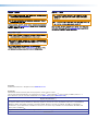
Contents
Introduction ...............................................1
About this Guide .................................................. 1
Features .............................................................. 2
Application Example ............................................ 3
Installation .................................................4
Mounting Instructions .......................................... 4
Installing the Wallplate on a Non-masonry
Wall ................................................................ 5
Installing the Wallplate on a Masonry Wall ........ 7
Attaching the SB 33 A to the Wallplate ............ 9
Mounting a Camera ....................................... 11
SMK V SB 33 VESA Mounting Kit ...................... 20
Installation ..................................................... 20
Aligning the SB 33 Speaker to the Display ..... 26
Operation .................................................27
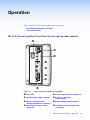
SB 33 A Internal Amplifier Front Panel (inside
right speaker module) ....................................... 27
Internal Adjustments .......................................... 31
Setting Bass and Treble ................................. 31
Reference Information ............................. 32
Defeating the Auto Power-down Timer .............. 32
Troubleshooting ................................................. 35
Amplifier Fails to Exit Standby Mode
Promptly ....................................................... 35
Amplifier Enters Standby Mode Too Early ....... 35
SB 33 A Series User Guide • Contents vii

SB 33 A Series User Guide • Contents viii

Introduction
This section gives an overview of the Extron SB 33 A Series Sound Bar Speaker. Topics
include:
• About this Guide
• Overview
• Features
• Application Examples
About this Guide
This guide describes the installation and set up of the SB 33 A Series Speaker.
NOTE: Observe all applicable building codes and local ordinances when installing the
SB 33 A speaker.
In this guide, the terms “speaker” and “sound bar” are used interchangeably to refer to the
SB 33 A Series Sound Bar Speaker.
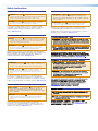
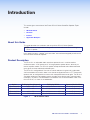
Product Description
The SB 33 A is an adjustable-width sound bar speaker for use in small-to-medium
conference rooms. It will feature two 3" full range speaker speaker drivers, driven by an
internal amplifier module. The SB 33 A speaker accepts balanced and unbalanced stereo
input signals on three individually buffered inputs.
The SB 33 A is configurable for use with an internal webcam using the built-in adjustable
shelf and window with a built-in door. It can also be configured to mount a PTZ camera with
optional shelf, or configured for no camera with the optional blank center grille. The SB 33 A
sound bar enclosure is adjustable to match the width of the display and is mounted under
the display. The SB 33 A will be offered in four different sizes to accommodate screen sizes
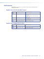
from 46" to 80", as shown in the table below.
Option Fit Display Size (diagonal) Fit Display Width Speaker Module Width
SB 33 A 46-55 46" — 55" 40" — 49" (101.6 cm — 124.5 cm) 16.25" (41.3 cm)
SB 33 A 55-65 55" — 65" 48" — 57" (121.9 cm — 144.8 cm) 20.25" (51.4 cm)
SB 33 A 65-70 65" — 70" 56" — 65" (142.2 cm — 165.1 cm) 24.25" (61.6 cm)
SB 33 A 75-80 75" — 80" 64" — 73" (162.6 cm — 185.4 cm) 28.25" (71.8 cm)
Figure 1. SB 33 A Series Table
SB 33 A Series User Guide • Introduction 1

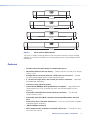
40"- 49"
SB 33 A 46-55
48"- 57"
SB 33 A 55-65
56"- 65"
SB 33 A 65-70
64"- 73"
SB 33 A 75-80
Figure 2. SB 33 A Series Model Options
The SB 33 A supports mounting directly to the wall under the display using the included
wallplate. It can also be attached to an articulating display mount using the optional VESA
mounting kit.
Features
• Provides enhanced audio quality for collaboration spaces
• Adjustable width to match the display — Perfectly matches the width of any display
from 46” to 80”
• Configurable for an internal webcam, a PTZ camera, or no camera — Suitable
for self-contained huddle spaces or video conference rooms
• 3” (76 mm) full-range drivers with a tuned port for bass extension — Optimized
for collaboration applications
• Frequency range: 100 Hz to 20 kHz
• Internal Extron ENERGY STAR qualified Class D amplifier — High performance
stereo amplifier with CDRS, automatic clip limiter, and auto power-down with fast
power-up
• Compatible with VCM series volume and mute controllers — Can be used
without a control system
• Compatible with select MLC controllers that include VCM volume and mute
ports
• Internal level, bass, and treble adjustments — Once set, these controls are hidden
and protected from tampering
• Optional VESA mounting kit
• ADA compliant when used with the included wall bracket — Protrudes less than
four inches from the wall
SB 33 A Series User Guide • Introduction 2

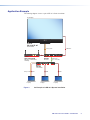
Application Example
The following diagram shows a typical SB 33 A Series installation.
Extron
ANT A ANT B
ShareLink 250 W
1 2
USB
HCR 102
CONFIG
1
SIGNAL
HDCP
LPCM-2CH
MULTI-CH
1
R
INPUT AUDIO
MENU
ENTER
HOLD FOR 72 0p/1080p
HCT 103
2
INPUTS
2 3 4
SIGNAL
HDCP
3 4
Extron
ShareLink 250 W
Wireless Collaboration
Gateway
Extron
HC 404
Receiver
Extron
HC 404
Transmitter
Laptop Laptop
CATx Cable
up to 230' (70m)
HDMI
HDMI/CEC
HDMIHDMI
Laptop
VGA
Analog Audio
Analog Audio
55'' Display
Extron
SB 33 A 55-65
Sound Bar
Figure 3. An Example of a SB 33 A System Installation
SB 33 A Series User Guide • Introduction 2

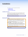
Installation
Topics covered in this section of the guide include the following:
• Installation Overview
• Mounting Instructions
• SMK V SB 33 VESA Mounting Kit
Installation Overview
The installation of the SB 33 A speaker includes using the included wallplate to mark the
wall where the SB 33 A will be mounted. After the wallplate is attached to the wall the
SB 33 A is then attached to the wallplate. The following section describes the mounting
procedure for safely and securely mounting the speaker.
NOTE: Install the wallplate onto wall material using common installation methods with
applicable hardware dictated per local building code.
Mounting Instructions
WARNING: Risk of personal injury or property damage. The final installation
should be able to continuously support the speaker weight. The final installation
should also be able to support any short term overloading. Since applications can
vary considerably, it is assumed that the installer will exercise good judgment when
selecting the mounting location, method, and hardware. Installation and service must
be performed by authorized personnel only.
AVERTISSEMENT : Risque de dommages corporels ou matériels.
L’installation finale doit pouvoir supporter en permanence le poids de l’enceinte.
L’installation finale doit également supporter toute surcharge temporaire. Étant donné
la possibilité d’évolution considérable des applications, il est supposé que l’installateur
fera preuve de discernement lors de la sélection de l’emplacement, du mode, et
du matériel de montage. L’installation et la maintenance du système doivent être
exclusivement effectuées par le personnel autorisé.
NOTE: Observe all applicable building codes and local ordinances when installing the
SB 33 A speaker.
SB 33 A Series User Guide • Installation 4

Installing the Wallplate on a Non-masonry Wall
NOTE: When attaching the wallplate to masonry, see Installing the Wallplate on a
Masonry Wall in the following section.
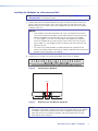
1. Position and level the included wallplate (see figure 4) under the display screen (see
figure 5) and mark the locations of the wall studs through the top vertical slots and
bottom horizontal slots where screws (not included) will secure the SB 33 A speaker
wallplate to the wall.
NOTES:
• If the wallplate cannot be attached to two studs, the wallplate can be offset
such that one side of the wallplate can be attached to one stud and the other
end of the wallplate can be attached to the wall using two (not included)
1/4" Kap Toggles. If the stud must come down the middle of the wallplate,
secure the wallplate to the stud using two screws and to the wall using two
(not included) 1/4" Kap Toggles (one on the leftmost top slot and one on the
rightmost top slot)
• The center of the wallplate does not need to be precisely aligned with the
center of the display above it because the speaker module on either end of the
wallplate can be adjusted on the wallplate.
2. If necessary, cut a hole in the wall to route cables to the SB 33 A speaker.
Figure 4. Positioning the Wallplate
Display
Left Speaker ModuleCenter
Bracket
Right Speaker Module
Figure 5. Display Screen and SB 33 A Alignment
NOTE: Assuming that the display screen is level, allow for some space between
the bottom of the display screen and the top of the speaker because the speaker
assemblies and the center bracket attach to the wallplate by hooking the top
mounting clasps of the speaker assemblies and center bracket over the top
mounting rail of the wall plate.
SB 33 A Series User Guide • Installation 5

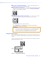
NOTE: To allow sufficient clearance between the top of the SB 33 A and the display
screen above it, allow for at least a minimum clearance of 11/16 inches (17.5 mm)
between the highest part of the top rail of the wallplate and the top of the speaker,
as shown below. The display screen should not encroach into this area above the
top rail.
INPUTS
POWER
MAX
12V
0.7A
OUTPUT
REMOTE
V
L
L
R
LEVEL BASS TREBLE
R
CG
10V 50mA
CLASS 2 WIRING
L SPEAKER
Wallplate
Side View
11/16"
(17.5 mm)
Wall
Minimum clearance between top of wallplate
and bottom of display is 11/16" (17.5 mm).
Figure 6. Positioning the Wallplate
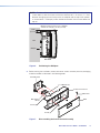
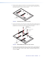
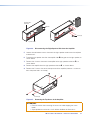
3. Before starting the installation, remove the center section assembly from the packaging
and disassemble as indicated in the following order:
Screws (2)
Grille
Center Section Cover
Lock Washers (2)
Center Bracket
Screws (2)
Web Camera
Mount
Grille Hoo
k
Figure 7. Disassembling the Center Section Assembly
SB 33 A Series User Guide • Installation 6

a. The front grille from the center section cover using a grille hook.
b. The center section cover from the center bracket standoffs by removing the 2
screws
c. The web camera mount from the center bracket (if necessary) by removing the two
screws and lock washers that attach it to the center bracket.
4. Drill four pilot holes through the marked locations on the wall.
5. Screw the wallplate to the wall studs using four #14 x 1 3/4" self-tapping wood or
metal screws and four 1/4" SAE washers into the pilot holes.
NOTE: Use wood or metal screws depending on whether the studs are wood or
metal.
Wall Stud
Wallplate
1/4" SAE Washer (x4)
#14 x 1 3/4" Self-tapping
Metal/Wood Screws (x4)
Figure 8. Attach the Wallplate to Studs
Installing the Wallplate on a Masonry Wall
Mount the wallplate on a brick, stone, or concrete wall by doing the following:
NOTE: The center of the wallplate does not need to be precisely aligned with the
center of the display above it because the speakers on either end of the wallplate
may still be adjustable on the wallplate.
1. Follow steps 1 to 3 of Installing the wallplate on a non-masonry wall on page 5.
NOTE: Because masonry installation does not involve wall studs, position the
wallplate so that the mounting holes will evenly distribute the weight of the
SB 33 A.
SB 33 A Series User Guide • Installation 7

2. Using a masonry drill bit, drill four pilot holes in the masonry wall at the locations you
marked in step one.
NOTE: If you drill the pilot hole too shallow, the screw head might break off while
it is being fastened into the hole.
Mounting Holes
Mounting Holes
Wallplate
Figure 9. Positioning the Wallplate on Masonry
3. For each pilot mounting hole:
a. Insert a 1/4" x 1 3/4" masonry screw through a 1/4" SAE washer.
b. Position the wallplate over the pilot holes
c. Insert each screw and washer through the wallplate and into the pilot hole.
Wallplate
1/4" SAE Washer (x4)
1/4" x 1 3/4"
Masonry Screws (x4)
Figure 10. Attaching the Wallplate to Masonry
d. Securely tighten the four screws to the wallplate.
SB 33 A Series User Guide • Installation 8

Attaching the SB 33 A to the Wallplate
ATTENTION:
• When attaching either speaker assembly or the center section to the wallplate, avoid
damaging or scratching the speaker assembly and center section cover.
• Lorsque vous xez les enceintes ou la section centrale à la plaque murale, prenez garde
à ne pas endommager ni à rayer les enceintes et le couvercle de la section centrale.
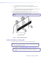
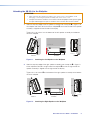
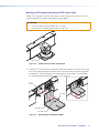
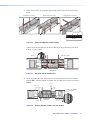
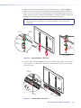
1. Hook the top clasp edge of the left speaker assembly over the top rail 1 in figure 11 of
the wallplate and slide it to left end of the wallplate 2 so that the left end of the speaker
assembly is aligned with the left end of the display.
Tighten the 2 set screws 3 on the bottom of the left speaker assembly to the bottom
rail of the wallplate.
Wallplate
Screws (2)
Left Speaker
11
3
3
DISPLAY
Left Speaker
Wallplate
Side View Side ViewFront View
Wall Wall
22
Figure 11. Attaching the Left Speaker to the Wallplate
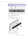
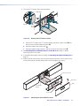
2. Hook the top clasp edge of the right speaker assembly over the top rail 1 in figure 12
of the wallplate and slide it to right end of the wallplate 2 so that the right end of the
speaker assembly is aligned with the right end of the display.
Tighten the 2 set screws 3 on the bottom of the right speaker assembly to the bottom
rail of the wallplate.
INPUTS
POWER
MAX
12V
0.7A
OUTPUT
REMOTE
V
L
L
R
LEVEL BASS TREBLE
R
CG
10V 50mA
CLASS 2 WIRING
L SPEAKER
INPUTS
POWER
MAX
12V
0.
7A
OUTPUT
REMOTE
V
L
L
R
LEVEL
BASS TREBLE
R
C G
10V 50mA
CLASS 2 WIRING
L SPEAKER
Side View Side ViewFront View
Screws (2
)
33
Right Speaker
Wallplate
22
DISPLAY
Wall
Wall
Wallplate
Right Speaker
11
Figure 12. Attaching the Right Speaker to the Wallplate
SB 33 A Series User Guide • Installation 9

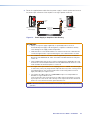
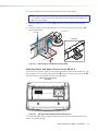
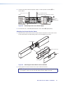
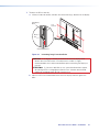
3. Route the supplied power cable from the power supply in the left speaker enclosure to
the power input connector of the amplifier in the right speaker enclosure.
INPUTS
POWER
MAX
12V
0.7A
OUTPUT
REMOTE
V
L
L
R
LEVEL BASSTREBLE
R
CG
10V 50mA
CLASS 2 WIRING
L SPEAKER
POWER
12V
0.7A MAX
Left Speaker Module
Power Supply
Right Speaker Module
Amplifier
DC Power
Input
DC Power Cord
Captive Screw
Connectors
Tie
Wraps
DC Power
Outputs
Figure 13. Power Supply to Amplifier Cable Routing
ATTENTION:
• Always use a power supply supplied by or specied by Extron. Use of an
unauthorized power supply voids all regulatory compliance certication and may
cause damage to the supply and the end product.
• L’utilisation d’une source d’alimentation non autorisée annule toute certication de
conformité réglementaire, et peut endommager la source d’alimentation et l’unité.
• The installation shall be in accordance with the applicable provisions of National
Electrical Code ANSI/NFPA 70, article 725 and the Canadian Electrical Code part1,
section 16.
• Cette installation doit toujours être conforme aux dispositions applicables du Code
américain de l’électricité (National Electrical Code) ANSI/NFPA 70, article 725, et du
Code canadien de l’électricité, partie 1, section 16.
• The length of the exposed wires in the stripping process is critical. The ideal length
is 3/16 inches (5 mm). Any longer and the exposed wires may touch, causing a short
circuit between them. Any shorter and the wires can be easily pulled out even if
tightly fastened by the captive screws.
• La longueur des câbles exposés est primordiale lorsque l’on entreprend de les
dénuder. La longueur idéale est de
5 mm (3/16 inches). S’ils sont trop longs, les câbles exposés pourraient se toucher
et provoquer un court-circuit. S’ils sont trop courts, ils peuvent être tirés facilement,
même s’ils sont correctement serrés par les borniers à vis.
NOTE: Do not tin the wires. Tinned wire does not hold its shape and can become loose
over time.
SB 33 A Series User Guide • Installation 10

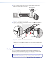
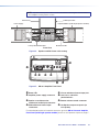
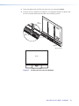
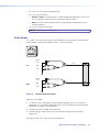
4. Route the supplied speaker cable from the left speaker module to the left speaker
output of the amplifier (
2
), as shown below.
e
INPUTS
OUTPUT
V
LEVEL BASS TREBLE
C
10V 5
CLASS 2 WIRING
L SPEAKER
e
INPUTS
WER
MAX
L
L
R
LEVEL
R
Right Speaker Amplifier
Side View
Front View
Amplifier
Audio Input
Connectors
Speaker Cable
Left Speaker Cable
Output
Speaker Cable
Power Cable
22
1
1
Figure 14. Left Speaker Cable Routing
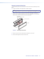
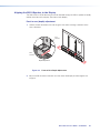
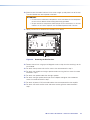
5. Hook the top clasp edge of the center bracket over the top rail (
1
) of the wallplate and
slide it to center of the display.
POWER
12V
0.7A MAX
INP
Screws (2)
22
11
Wallplate
Center Bracket
Side View
Side View
Wall
Wall
Figure 15. Center Bracket to Wallplate Installation
Tighten the two set screws (
2
) on the bottom of the center bracket to the bottom rail of
the wallplate.
NOTE: If a camera is to be mounted to the center bracket, see Mounting a
Camera before proceeding to the next step.
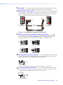
Mounting a Camera
The SB 33 A speaker can accommodate a camera mounted to the center bracket. A
small webcam can be mounted behind the center cover, and a larger PTZ camera can be
mounted in front of the center cover using an optional PTZ camera shelf.
NOTE: If mounting a PTZ Camera, please go to Mounting a PTZ Camera wiith
optional PTZ camera shelf section. Both the webcam camera shelf and the PTZ
camera shelf use the same two attaching screws and lock washers.
SB 33 A Series User Guide • Installation 11

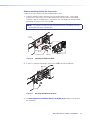
Camera mounting behind the front cover
A webcam can be installed using the included webcam shelf.
1. Install the webcam shelf by attaching it to the center bracket using 2 screws going
through the 2 vertical slots on the shelf and into two mounting holes in the bracket.
There are 2 pairs of available holes in the bracket. The shelf height can be adjusted by
positioning the screws in the shelf slots 1.
NOTE: For cameras that require more overhead clearance, the webcam shelf can
be inverted (see Option 2 below right).
POWER
12V
0.7A MAX
INP
Screws (2)
Lock Washers (2)
Web Camera
Mount
Center
Bracket
11
Option 2
Figure 16. Inverting the Webcam Shelf
2. A screw is inserted in the bottom slot of the shelf 2 to secure the webcam.
POWER
12V
0.7A MAX
INP
Screw
Webcam
22
Figure 17. Securing the Webcam to Shelf
3. See Attaching Power and Audio Sources to the SB 33 A on page 15 to continue
the installation.
SB 33 A Series User Guide • Installation 12

Mounting a PTZ camera with optional PTZ camera shelf
A larger PTZ camera that takes up more space can be installed in front of the front cover
using the optional PTZ camera shelf. Follow the steps below.
ATTENTION:
• The PTZ camera cannot exceed 4 lbs. (1.81 kg).
• La caméra PTZ ne peut peser plus de 1,81 kg (4 lb).
POWER
12V
0.7A MAX
INP
PTZ Camera
Figure 18. PTZ Camera on PTZ Camera Shelf
1. Install the PTZ camera shelf by attaching it to the center bracket using two screws and
lock washers going through the vertical slots on the shelf and into two mounting holes
in the bracket. There are two pairs of available holes in the bracket. The shelf height
can be adjusted by positioning the screws in the shelf slots.
POWER
12V
0.7A MAX
INP
POWER
12V
0.7A MAX
INP
Screws (2)
PTZ Camera Shelf
Center
Bracket
Lock Washers (2)
Figure 19. Attaching the PTZ Camera Shelf
SB 33 A Series User Guide • Installation 13

2. To install a PTZ camera, follow the steps below:
POWER
12V
0.7A MAX
IN
P
Cable
Tie-off
Point
Zip Tie
PTZ Cables
44
3
3
1
1
2
2
Figure 20. Routing the PTZ Camera Cable
a. Route the PTZ cable to the PTZ camera through the center section cover (
1
) and
along a center bracket cable tie-off point (
2
).
b. Route the cable to the camera shelf (
3
).
c. Route the cable through the access hole at the rear of the camera shelf (
4
).
3. See Attaching Power and Audio Sources to the SB 33 A on page 15 before
continuing with the next steps.
4. If the optional blank grille is being installed, see Attaching the optional blank grille on
page 19.
5. Slide the center section cover over the center bracket and attach the two cover screws
to the center bracket standoffs being careful not to overtighten the screws.
POWER
12V
0.7A MAX
INP
Screws (2)
Grille
Center Section Cover
Center Bracket
Standoff
Grille Hoo
k
Figure 21. Attaching the Center Section Cover
SB 33 A Series User Guide • Installation 14

6. Attach the grille to the center section cover. See the illustration above.
NOTE: Two grille hooks are included to facilitate grill removal while avoiding damage
to the grille. It is best to insert the hook along the top or bottom outer edge of the
grille, as shown above.
7. Route the cable to the PTZ camera (
1
) and attach it to the camera. See the figure
below.
8. Place the camera on the shelf and attach it to the shelf with the mounting screw (
2
).
See the figure below.
IN
P
IN
POWER
12V
0.7A MAX
I
NP
PTZ Camera
Screw
PTZ Cables
11
2
2
Final View
Figure 22. Attaching the PTZ Camera to the Shelf
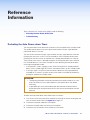
Attaching Power and Audio Sources to the SB 33 A
The SB 33 A has a power supply for the amplifier housed in the left speaker enclosure. The
power supply has an AC power input connector (
A
) and a DC power output connector (
B
)
that routes power to the amplifier. See the illustration below.
Left Speaker/Power Supply
(Side View)
AABB
Figure 23. AC Input and DC Output Power Connectors
This section describes how the power and audio sources are attached to the SB 33 A, as
shown in the following steps.
SB 33 A Series User Guide • Installation 15
La page est en cours de chargement...
La page est en cours de chargement...
La page est en cours de chargement...
La page est en cours de chargement...
La page est en cours de chargement...
La page est en cours de chargement...
La page est en cours de chargement...
La page est en cours de chargement...
La page est en cours de chargement...
La page est en cours de chargement...
La page est en cours de chargement...
La page est en cours de chargement...
La page est en cours de chargement...
La page est en cours de chargement...
La page est en cours de chargement...
La page est en cours de chargement...
La page est en cours de chargement...
La page est en cours de chargement...
La page est en cours de chargement...
La page est en cours de chargement...
La page est en cours de chargement...
-
 1
1
-
 2
2
-
 3
3
-
 4
4
-
 5
5
-
 6
6
-
 7
7
-
 8
8
-
 9
9
-
 10
10
-
 11
11
-
 12
12
-
 13
13
-
 14
14
-
 15
15
-
 16
16
-
 17
17
-
 18
18
-
 19
19
-
 20
20
-
 21
21
-
 22
22
-
 23
23
-
 24
24
-
 25
25
-
 26
26
-
 27
27
-
 28
28
-
 29
29
-
 30
30
-
 31
31
-
 32
32
-
 33
33
-
 34
34
-
 35
35
-
 36
36
-
 37
37
-
 38
38
-
 39
39
-
 40
40
-
 41
41


Extron SMK V SB 33 Manuel utilisateur
- Catégorie
- Amplificateurs audio
- Taper
- Manuel utilisateur
- Ce manuel convient également à
dans d''autres langues
- English: Extron SMK V SB 33 User manual
Documents connexes
-
Extron SB 33 A Series Manuel utilisateur
-
Extron SMK V SB 33 Manuel utilisateur
-
Extron SM 28 Manuel utilisateur
-
Extron MPA 152 Plus Manuel utilisateur
-
-
Extron MDA 4V EQ Manuel utilisateur
-
-
-
Extron NBP 100 Manuel utilisateur
-