Flotec FPDC30 Le manuel du propriétaire
- Catégorie
- Pompes à eau
- Taper
- Le manuel du propriétaire

pentair.com
FP979 (06-08-20) ©2020. All Rights Reserved.
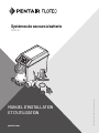
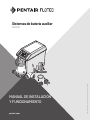
INSTALLATION AND
OPERATION MANUAL
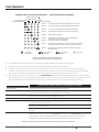
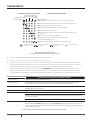
Battery Backup Systems
FPDC 30
Pump Activity
Activité de pompe
Actividad de la bomba
System Alert
Alerte du système
Alerta del sistema
AC Power
Courant AC
CA
Charging
Recharge
En carga
Battery Status
État de batterie
Estado de la batería
Alarm Silenced
Alarme arrêtée
Alarma apagada
Test System
Tester
Probar sistema
Silence Alarm
Arrêter l’alarme
Apagar alarma
Light
Lumière
Luz
Circuit Breaker
Disjoncteur
Disyuntor
Pump
Pompe
Bomba
Float Switch
Interrupteur à otteur
Interruptor del otador
Power
Courant
Encendido
Reset System
Réinitialise
Restrablecer sistema
+
ENGLISH: 1-17
FRANCAIS: 18-34
ESPANOL: 35-51

2
FP979 (06-08-20)
TABLE OF CONTENTS
SECTION .................................................................................................................................................................................................. PAGE
Safety Information ..................................................................................................................................................................................3
General Information ................................................................................................................................................................................4
Internet And Alerts Setup ........................................................................................................................................................................5
Installation ..............................................................................................................................................................................................6
Operation ............................................................................................................................................................................................... 12
Troubleshooting .................................................................................................................................................................................... 15
Parts List ............................................................................................................................................................................................... 16
Warranty ................................................................................................................................................................................................ 17

3
FP979 (06-08-20)
IMPORTANT SAFETY INSTRUCTIONS
SAVE THESE INSTRUCTIONS - This manual contains important
instructions that should be followed during installation,
operation, and maintenance of the product.
This is the safety alert symbol. When you see this symbol
on your pump or in this manual, look for one of the following
signal words and be alert to the potential for personal injury!
indicates a hazard which, if not avoided, will
result in death or serious injury.
indicates a hazard which, if not avoided, can
result in death or serious injury.
indicates a hazard which, if not avoided, can or
may result in minor or moderate injury.
NOTE: addresses practices not related to personal injury.
Keep safety labels in good condition. Replace missing or
damaged safety labels.
To avoid risk of serious bodily injury due to electrical shock
or burns and property damage due to flooding, carefully
read the safety instructions in this manual and on the
pump before installing pump.
Battery acid is corrosive. Do not spill on
skin, clothing, or battery charger. Wear eye and head
protection when working with battery. Connect and
disconnect DC output terminals only after removing the
charger from the AC outlet. Never allow the DC terminals to
touch each other.
Hazardous Voltage. Can cause severe or
fatal electrical shock. Do not plug in or unplug battery
charger while standing on a wet floor or in water. Be sure
one hand is free when plugging in or unplugging charger. If
basement floor is wet, disconnect power to basement
before walking on floor.
Risk of flooding. Do not run pump dry.
To do so will damage seals and can cause leaking
and property damage.
Follow local and/or national plumbing and electrical
codes when installing the system. A ground fault circuit
interrupter (GFCI) is recommended for use on any
electrical appliance submerged in water.
Use this system only for backup sump pump duty in a
residential application. It is not designed as a primary
sump pump.
Do not lift pump by electrical cord.
Risk of electrical shock. Do not lift the
pump by the electrical cord; lift pump only by the
discharge pipe, lifting ring or handle on the pump. Lifting
by the cord can damage the cord.
Pump clear water only with this pump.
Pump is permanently lubricated at the factory. Do not try
to lubricate it!
Keep battery charger and battery box off of the floor and
in a dry, cool, well ventilated area.
NOTICE: If a Carbon Monoxide (CO) sensor is installed,
it must be at least 15 feet away from battery charger in
order to avoid nuisance CO alarms. Please refer to your CO
detector’s installation guidelines for more information.
To avoid danger of fire or explosion, keep sparks and flame
(pilot light) away from battery.
Maximum vertical pumping distance is 15 feet (4.6M) for
Model FPDC30.
Make sure sump is clear of debris. Debris can damage the
pump which can result in flooding.
California Proposition 65 Warning
This product and related accessories contain
chemicals known to the State of California to cause cancer,
birth defects or other reproductive harm.
SAFETY INFORMATION

4
FP979 (06-08-20)
GENERAL INFORMATION
The battery backup sump system is not a substitute for your
primary sump pump. It is designed to temporarily backup your
primary sump pump during a power outage or other problem
which prevents normal operation of the primary pump. Do not
use this system to pump flammable liquids or chemicals. Pump
clear water only with this pump.
Keep the battery charger dry and protected from damage.
This system is designed to work with a deep cycle sealed
maintenance free lead-acid AGM battery. It will also work with
a flooded lead acid battery. Gel and Sealed flooded lead acid
batteries are not recommended.
In an emergency (such as an extended power outage) which
depletes the system deep cycle battery, your automobile
battery may be temporarily substituted. Be sure to replace the
system deep cycle battery as soon as possible.
Use of an automobile battery instead of a deep cycle battery
in this system will significantly reduce the system’s total
performance. Automobile batteries are not designed for this
type of application and will be quickly ruined by the repeated
charge/discharge cycling.
NOTE: This system is not designed for applications involving salt
water, brine, or where fish may be present! Use with these will
void warranty.
BASIC TOOLS AND PARTS NEEDED (PURCHASE SEPARATELY)
Tongue and groove or large adjustable pliers
Tape measure
Socket wrench or 5/16” nut driver
Side cutters
Hacksaw (to cut PVC pipe)
Medium size pliers
Slotted screwdriver
Phillips head screwdriver
Pencil or marker
PTFE pipe thread sealant tape
PVC glue (solvent weld)
PVC pipe cleaner
Cloth towel
Plastic fittings
Check valve(s) - 1 or 2 depending on installation
38-120 Ampere-Hour Storage or Deep Cycle Battery
REQUIRED BATTERY CAPACITY
For best results, use the following AGM Storage Batteries.
Part Amp-Hour
Gal/Charge
at 10’
Approx Run
Time
BAT40 40 4,800 5 Hours
Unit equipped with dual battery capability
Maximum amp-hour: 120
NOTE: The charger will not fully charge batteries with excessive amp
hour ratings without resetting system.
BATTERY BACKUP SYSTEM (BBU) INSTALLATION AND OPERATION
Install this system during a time when the primary pump will not
be needed.
Gather all supplies before starting.
Read all warnings and installation steps before you start.
Be prepared for water to leak from the coupling or piping when
disassembling or cutting the discharge pipe. Protect system
components, tools and supplies from getting wet. Dry any work
areas that get wet.
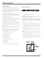
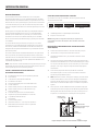
Study pages 5-8 to determine which installation method will be
best for you. The “Separate Discharge” (Figure 2), installation is
recommended.
NOTE: Check your local codes and ordinances regarding waste
water disposal (especially when running the pump discharge
outside the house) before you start. The installation must
conform to all legal requirements.
If possible, install the BBU so that the discharge goes directly
outdoors (separate discharge pipe from the primary sump pump
discharge pipe). If this is not a practical option, see the “Common
Discharge” (Figure 3) option.
GENERAL INFORMATION
Figure 1: Mark Pipe at ‘Start’ Water Level
6781 0916

5
FP979 (06-08-20)
INTERNET AND ALERTS SETUP
BATTERY BACKUP INTERNET CONNECTION AND ALERTS
CONFIGURATION
1. Complete the Battery Backup Registration, Internet
Connection and Alert Configuration BEFORE connecting
the battery and AC power supply to your BBU.
NOTE: If you have already connected the battery and
AC power supply to the BBU before connecting to to the
internet, complete the device registration process.
Then disconnect the battery and remove the AC power
supply from the BBU panel and gateway for 2 minutes in
order to reset the panel. Resume with Step 8.
2. Download the Pentair Home app to your mobile device
from the App Store® or Google Play™ Store.
3. Open the app.
EXISTING USERS: LOGIN to your account.
NEW USERS: Scroll down in the App and click SIGN
UP.
4. Enter a valid EMAIL and PASSWORD.
5. Select TERMS OF SERVICE.
6. Click CREATE AN ACCOUNT.
7. Complete instruction in the VERIFICATION EMAIL
8. LOGIN to your account.
9. Register your device using the Unique Device ID Key
included on the device and your manual cover.
10. The Alerts will use the e-mail(s) and phone number(s)
entered here.
11. Find an open network connection on your internet router
or other hardwired connection (like an internet switch).
12. Rotate the Gateway antenna up on the gateway. Using
the supplied 1 meter Ethernet cable (or a longer cable if
necessary)
13. Connect the Gateway to the open internet port
14. An uninterrupted power supply for your internet modem,
home router and the gateway power supply is recommended.
15. Connect the Gateway power supply to a 115 VAC outlet, plug
the cord into the back of the Gateway.
The Gateway will blink red for a few seconds.
When the LED becomes solid Green or solid Green with
an occasional blink – your Gateway is communicating with
the server. If not, refer to Gateway Trouble in the manual.
16. Connect the red positive (+) charger/controller lead wire to the
positive (+) (red) battery terminal.
17. Connect the black negative (-)charger/controller lead wire to
the negative (-) (black) battery terminal.
18. Connect the Charger Power Supply cable (supplied) to the
Charger/Controller’s Power input jack. Plug the other end into
a 115 VAC outlet.
19. Check the AC power LED on the Controller. If it is solid green
the unit is communicating with the web site.
20. Verify the system is operational by pressing the TEST
SYSTEM button and observing the test sequence.
21. Test communication by clicking the Test icon on the web page
and verify the unit has run the test.
22. Using the drop down menu, configure the desired method of
Alerts you want to receive: text or email.
23. Alerts can be tested by activating the pump with thefloat
switch.
Gateway Status Definition Action Needed
Green Power on. Gateway connected to servers. OK - Connection complete and operational
Green, quick blink Power on. Data trac to servers. OK - Operating, data is moving between BBU and server
Green, slow blink
(1-2 blinks per second)
Power on. Gateway connected to local router, but not
connected to Internet or servers.
System is online and scanning for destination/server
(add a network switch inline to help dene unit).
Red Power on. Gateway has no local connection to
router. The gateway does not recognize/see that it is
connected to the router.
Check Ethernet cable connections and/or quality or
cable. Try a different router port. Is the router turned on.
Red, slow blink
(1-2 blinks per second)
Power on. Gateway communicating with router, but
router cannot assign Dynamic Host Conguration
Protocol (DHCP) or Domain Name System (DNS) to
gateway.
Router is not permitting the gateway to access the
internet (add a network switch inline to help dene unit).
Off Power off or product fault. Check power source, verify power adapter is
functioning. Defective gateway.
Table I: Gateway Troubleshooting

6
FP979 (06-08-20)
INSTALLATION
INSTALLATION (TYPICAL): SEPARATE DISCHARGE
Unplug the primary sump pump before beginning this
procedure. Risk of electrical shock. Can shock,
burn, or kill.
1. Allow for overlap when cutting piping and run a trial (dry)
fitting before you glue.
2. Use PTFE pipe thread sealant tape on male ends of
discharge pipe. Thread the 1-1/4” x 1-1/2” elbow (supplied)
onto the discharge. When tight, the elbow must point up.
3. If possible, install the Battery Backup Unit (BBU) on
the floor of the sump. Be sure that the two pumps do
not touch each other and do not interfere with switch
operation.
NOTE: If debris or gravel is present in the bottom of the
sump pit that could get sucked up into the pump, set
both the primary sump pump and the BBU up on bricks or
cinder blocks to prevent clogging.
4. If the sump is too small to allow both pumps to sit on
the bottom of the sump, install an angle bracket on the
primary sump pump’s discharge pipe with stainless steel
hose clamps.
Mount the backup pump on the angle bracket (Figure 2).
5. Cut a piece of 1-1/2” PVC pipe to reach from the backup
pump discharge elbow to about one (1) foot above the
basement floor. This is the lower discharge pipe.
6. To prevent airlocking the pump during operation, drill a
1/8” hole in the lower discharge pipe about 2” above the
bottom of the pipe (below floor level).
7. Install FP0026-10 check valve (sold separately) on the
upper end of the pipe.
Tighten the hose clamps securely. BE SURE that the flow
arrows point UP (away from the BBU). If they point down,
the valve will not pass water and the pump will not work.
8. Cut a short length of 1-1/2” PVC pipe for a riser pipe and
clamp it into the top of the check valve.
9. Install a hose and clamp assembly (sold separately) on the
top of the riser pipe. For 1-1/2” pipe, remove and discard
the short piece of 1-1/4” hose in the Hose and Clamp
Assembly. Leave the hose clamps loose and slide the
Assembly down below the top of the riser pipe.
10. Determine where you want the discharge to exit the
basement. At that point, drill the necessary holes (large
enough to have clearance for a 1-1/2” pipe) to allow you
to run the discharge pipe from above the sump to the
outdoors.
11. Install the horizontal discharge pipe. Install a 90° elbow on
the inside end but do not glue.
12. Cut another short piece of 1-1/2” PVC for the Upper
Discharge Pipe to run from the top of the riser pipe up to
the 90° elbow. Be sure to allow enough overlap for the glue
joint in the elbow.
13. Do a trial fit with NO GLUE, installing the 1-1/2” upper
discharge pipe in the 90° elbow and the upper discharge
pipe in the vertical end of the 90° elbow.
The upper discharge pipe should just fit between the riser
pipe and the elbow.
14. Whenever using PVC primer and PVC cement, follow the
glue manufacturer’s instructions. Risk of
fire and chemical inhalation.
15. Make sure that the BBU clears the primary sump pump
and its switch. If there isn’t room for both pumps to sit
on the floor of the sump, the BBU will have to be raised
(depending on your particular situation).
16. Clean, prime and glue the upper discharge pipe into the
90º elbow. When the glue has set, slide the Hose and
Clamp Assembly up to cover the joint and tighten all the
hose clamps.
17. Install the Battery Backup Switch as shown, 1” above start
water level of primary pump. Fasten it to the pipe with
cable ties.
18. Tape the pump cord to the riser pipe so that the plug
cannot fall into the sump.
19. Go to BBU WIRING AND SETUP section of this manual for
wiring instructions.
20. Once all wiring is complete, fill your pit with water and
verify that the primary sump pump removes the water and
the BBU doesn’t run.
21. Then, unplug your primary sump pump and refill your pit
with water. Verify that the BBU pump removes the water.
22. Make sure that the power is on to both pumps, and your
system is ready to use.

7
FP979 (06-08-20)
INSTALLATION
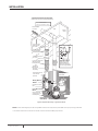
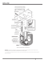
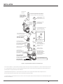
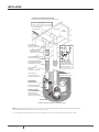
Figure 2: Separate Discharge - Typical Installation
NOTE: Check valve flapper(s) must swing AWAY and flow arrow(s) must point AWAY from pump being protected.
* The water level when the switch shuts off must be above the BBU pump intake.
FLOW
Slope DOWN
to outlet
Sill
FP0026-10
Check Valve
(Purchase
Separately)
PTFE pipe thread
sealant tape on all
threaded joints
1-1/2” PVC Riser Pipe
(cut to t)
1-1/4” FNPTx1-1/2” Slip
Elbow*
Battery Back Up
Sump Pump*
Lower Discharge Pipe
1-1/2” PVC Pipe
(cut to t)
Primary Sump Pump
Check Valve
Flow Arrow; Must point
AWAY from Pump
being Protected
1-1/2” PVC Upper
Discharge Pipe
(cut to t)
Battery Backup
Switch*
If the sump is small,
hang the BBU from
the Primary discharge
pipe on an angle bracket.
Floor
Joist
U74-68 Hose and
Clamp Assembly
(Purchase Separately)
Drill 1/8” Anti-Airlock
Hole
6782 0313a
Not to scale.
Wiring omitted for clarity.
*
Supplied with the Battery Backup System.
Items in italics must be purchased separately

8
FP979 (06-08-20)
INSTALLATION
INSTALLATION (TYPICAL): COMMON DISCHARGE
Unplug the primary sump pump before beginning this
procedure. Risk of electrical shock. Can shock,
burn, or kill.
1. Allow for over lap when cutting piping and run a trial (dry)
fitting before you glue.
2. If there is no check valve in the primary sump pump’s
discharge, you will need to install one. You must also
install one in the BBU’s discharge pipe (Figure 3). Make
sure that the check valve flow arrow points AWAY from the
pump it is protecting.
3. Use PTFE pipe thread sealant tape on male ends of
discharge pipe. Thread the 1-1/4” x 1-1/2” elbow (supplied)
onto the discharge. When tight, the elbow must point up.
4. If possible, position the BBU on the floor of the sump; be
sure that the two pumps do not touch each other and do
not interfere with switch operation.
NOTE: If debris or gravel is present in the bottom of the
sump pit that could get sucked up into the pump, set
both the primary sump pump and the BBU up on bricks or
cinder blocks to prevent clogging.
5. If the sump is too small to allow both pumps to sit on the
bottom of the sump, find a raised position that doesn’t
interfere with the Primary sump pump switch.
6. Cut a piece of 1-1/2” PVC pipe to reach from the backup
pump discharge elbow to about one (1) foot above the
basement floor. This is the lower discharge pipe.
7. To prevent airlocking the pump during operation, drill a
1/8” hole in the lower discharge pipe about 2” above the
bottom of the pipe (below floor level).
8. Install FP0026-10 check valve (purchase separately)
on the upper end of the pipe. Tighten the hose clamps
securely. BE SURE that the flow arrows point UP (away
from the backup pump). If they point down, the valve will
not pass water and the pump will not work.
9. Cut the discharge pipe for the primary sump pump
(Primary sump pump) above the union and check valve (if
any). Make this cut about 18” above the top of the BBU’s
riser pipe with the backup pump sitting as installed.
10. If the primary sump pump does not have a check valve
installed in the discharge pipe, install one now.
11. Cut a length of discharge pipe for the Primary sump pump
to fit between the check valve and a 45° slip wye. Be sure
to allow for the overlap needed for gluing joints.
12. Install the 45° wye on the Primary sump pump’s discharge
pipe.
13. Install a 45° elbow on the 1-1/2” BATTERY BACKUP
discharge pipe.
14. Fit the upper discharge pipe to the upper end of the wye.
NOTICE: It is good practice to cut a short length of pipe to
go into the wye and install a union on the pipe. Continue
the discharge pipe from the outlet side of the union.
This will allow easier removal of the system for cleaning
or service. A U74-68 Hose and Clamp Assembly (sold
separately) can be used for this.
15. Make sure that the BBU will clear the primary sump pump
and its switch. If there isn’t room for both pumps to sit
on the floor of the sump, the BBU will have to be raised
(depending on your particular situation).
16. Do a trial assembly to make sure that everything is
going to fit. This may require a helper to assist in holding
everything together while you check the fit without glue.
Mark all joints before gluing.
Follow the glue manufacturer’s instructions regarding fire
hazards and ventilation when using PVC solvents, primer,
and cement. Risk of fire and chemical
inhalation.
17. Take all the pipe apart, clean all joints, and then
reassemble the system, gluing it with PVC primer and
glue.
18. Install the Battery Backup Switch as shown, 1” above start
water level of primary pump. Fasten it to the pipe with the
cable ties provided.
19. Tape the pump cord to the riser pipe so that the plug
cannot fall into the sump.
20. Go to BBU WIRING AND SETUP section of this manual for
wiring instructions.
21. Once all wiring is complete, fill your pit with water and
verify that the Primary sump pump removes the water and
the BBU doesn’t run.
22. Then, unplug your Primary sump pump and refill your pit
with water. Verify that the BBU pump removes the water.
23. Make sure that the power is on to both pumps, and your
system is ready to use.

9
FP979 (06-08-20)
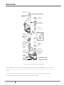
INSTALLATION
Battery Backup
Switch*
Primary Pump
Discharge Pipe
(cut to t)
Primary Sump Pump
Discharge Port
Primary Pump
Check Valve
Flow Arrow; Must point
AWAY from Pump
being Protected
45º Slip Elbow
PTFE pipe thread
sealant tape on all
threaded joints
1-1/4” FNPTx1-1/2”
Slip Elbow*
Battery Back Up
Sump Pump*
Thread to Slip
Adapter
45 degree Slip Wye
FLOW
Optional 1-1/2”
PVC Pipe (cut to t)
1-1/2” PVC Pipe
(cut to t)
Lower Drischarge Pipe
1-1/2” PVC Pipe
(cut to t)
AlternateWye/Elbow
Setup
45º Slip Street
Elbow
FLOW
*
Supplied with the Battery Backup System.
Items in italics must be purchased separately
Typical installation,
assembled.
Both check valves must
be installed on the pump
side of the wye.
FP0026-10
Check Valve
(Purchase
Separately)
1-1/2” PVC Riser Pipe
(cut to t)
1-1/2” PVC Upper
Discharge Pipe
(cut to t)
Flow Arrow; Must point
AWAY from Pump
being Protected
U74-68 Hose and
Clamp Assembly
(Purchase Separately)
Drill 1/8”
Anti-Airlock Hole
6783 0313a
Not to scale.
Wiring omitted for clarity.
Figure 3: Common Discharge Pipe - Typical Installation
In this installation, if the Primary Sump Pump (PSP) does not have a check valve installed below the wye, you MUST
install a check valve for the PSP as shown. This prevents backflow of water into the sump from the battery backup
system.
Check Valve Flapper(s) must swing away and flow arrow(s) must point away from the pump being protected.
The water level when the switch shuts off must be above the BBU pump intake.

10
FP979 (06-08-20)
INSTALLATION
BATTERY REQUIREMENTS
Install the battery in the battery case. To prevent accidental
shorting across battery terminals, close and latch the battery
case securely. Do not leave the battery uncovered.
Hazardous electric current. Can cause severe
burns and start a fire if the battery terminals are short
circuited.
Do not allow children to play around the battery backup
system installation.
The performance of your backup sump pump depends on
the battery used with it for power. We recommend using
our BAT40. You can also use a group 24M or 27M Deep Cycle
battery. They will provide acceptable performance and will
stand up well to long periods of little or no use.
This system is designed to work with either a sealed lead-acid
AGM battery or a flooded lead-acid battery. Use of a true Gell
Cell (often confused for AGM) or a standard automotive battery
with this charger is not recommended. An automotive battery
may require charging after only 1-2 hours of continuous use,
and the repeated charging cycles may cause early plate failure
in the battery.
Use only lead-acid batteries. This unit is not designed to
use with Li-Ion, NiMh, NiCAD, Liquid Polymer, etc.
Use only the recommended battery or one of the same
type and size so it will fit in the battery box (maximum size:
13” long x 7” wide x 10” tall (330.2mm x 177.8mm x 254mm)
including terminals) and supply enough voltage for full
performance.
BATTERY MAINTENANCE
To protect the battery case from chipping and gouging, do
not let the battery sit on a concrete floor.
Install the battery on a shelf or protective pad (plywood,
2x4s, etc.).
Always install the battery in a dry location that is
protected from flooding.
Severe burn hazard. An acid-filled standard
lead-acid battery contains sulfuric acid. Avoid contact with
skin, eyes or clothing.
PRE-QUALIFICATION TEST – 1 AND 2
Charger is charging at a very low level to try to bring a dead
battery back to life.
If the battery is taking too long, try resetting the charger once
or twice (push the System Test and Silence Alarm buttons
together to reset the charger).
SPECIAL FEATURES
The charger is equipped with reverse battery, short circuit,
and “runaway charge” protection.
POSSIBLE PROBLEMS AND REMEDIES
1. Wrong Battery Voltage: Reconnect charger to a 12 volt
battery.
2. Reversed Battery Connections: Check all connections.
The negative (black) on the battery must connect to the
negative (black) on the charger, and the positive (red)
on the battery must connect to the positive (red) on the
charger. Reversing the battery connections will cause the
System Alert and Silenced Audible Alarm LEDs to flash.
3. Thermal Runaway Condition: “Thermal Runaway” is the
technical term for the condition of the battery when some
(or all) of the cells have deteriorated to the point that they
won’t take a charge. In this case, replace the battery.
4. Charge Time Monitor – 1 and 2: Battery took too long to
complete its charge. The Charge Time Monitor will shut
down the charger after 84 hours of continuous charging.
Possible causes are:
Pump ran for a long period of time during charging, or
Battery is too large for the charger (including several
batteries connected in a parallel circuit).
EXCESSIVE BATTERY DRAIN
Pump may have run for a very long time, discharging the
battery.
1. If 115VAC power is OFF, the charger shuts down until the
power comes back on, but the pump will run as long as the
battery charge lasts. You may need to replace the battery
afterwards.
2. If 115VAC power is ON, the charger/controller continues to
try to charge the battery at a charging rate of .5 AH until
the battery charge is more than 20%, at which point the
charger will resume charging at a rate of 2 AH.
3. If the pump is running and the AC power is on, you may
need to stop the pump to allow the battery to charge.
Follow the battery manufacturer’s recommendations for
maintenance and safe use of the battery.

11
FP979 (06-08-20)
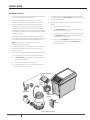
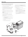
BBU WIRING AND SETUP
1. Connect the positive (+) charger/controller lead wire (red)
to the positive (+) battery terminal (red).
2. Connect the negative (–) charger/controller lead wire
(black) to the negative (–) terminal (black) on the battery.
3. If you are using two batteries, use the set of optional
terminals and connect the second battery. Use lead
wires (not included) to connect the positive (+) charger/
controller terminal to the positive (+) battery terminal and
the negative (–) charger/controller terminal to the negative
(–) battery terminal.
4. The backup pump leads are polarity sensitive. Connect
the positive pump lead to the terminal labeled Pump ‘+’ and
the negative pump lead to the terminal labeled Pump ‘–’.
NOTE: If the leads are reversed, the pump will run
backward and not pump water.
5. The float switch leads are not polarity sensitive. Connect
the float switch leads to the Float Switch tabs on the
charger/controller.
6. Test the float and the pump by lifting and holding the float.
The system alert LED will blink while the float is up.
The Pump Status LED will light continuously and the
buzzer will beep steadily.
The pump should start after 3 seconds.
If the pump does not run, check all the connections
and remake them as necessary.
7. To stop the pump, lower the float. After 25 seconds the
pump should stop, the Pump Status LED should flash, and
the buzzer should beep.
8. With the pump operating, test the ‘SILENCE ALARM’
button:
Hold for one second; release.
The Alarm Silenced LED should illuminate and the
buzzer should stop sounding.
To reset the buzzer (allow it to sound) and extinguish
the Alarm Silenced LED, press the ‘Silence Alarm’
button again for one second.
Depress the Test System button. Hold it for one
second and then release. The Pump Status LED
should stop flashing.
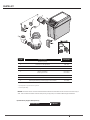
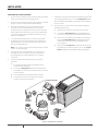
INSTALLATION
Charger/Controller
Float Switch
Backup Pump
Adaptor
Optional
Second Battery
Terminal
Lead
Wires
Figure 4: Wiring and Setup

12
FP979 (06-08-20)
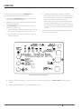
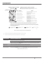
OPERATION
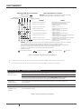
During normal operation, the flashing Pump Status LED
indicates that the pump has run in your absence.
Press and hold Test System button. All LEDs will light up,
pump will run and buzzer will sound.
Release the button and LEDs should go off, pump should
stop, buzzer should stop.
The Battery Status LED indicates the battery capacity
when the A.C. power is off.
1. Continuously ON - the battery voltage is above 10.9 Volts
Direct Current (10.9VDC) and capacity is above 20%.
2. Slow Beep/Slow LED Flash - the battery’s capacity is
between 0 and 20%.
3. Fast Beep/Fast LED Flash - the battery is severely
discharged. The battery will continue to charge (as long
as the 115V AC power to the charger is on) at the rate of
.5 AH until the battery’s charge is above 20%.
When the first warning occurs (slow beep/slow flash),
you will have approximately 2 hours (or less) of pump
operation left. The actual time of operation will depend
on the condition of the battery and may be as little as 15
minutes.
Connect the Power Supply cable (supplied) to the Charger/
Controller’s Power Input jack.
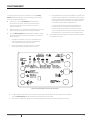
When the unit is first plugged in, or when it first receives power from the battery, the Battery Status LED will flash for 3
seconds.
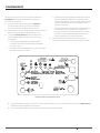
To activate any Control Button, press and hold it for 1 second.
Figure 5: LED Display and Control Buttons

13
FP979 (06-08-20)
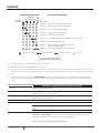
OPERATION
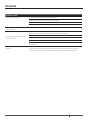
LED Operating Code Display
System Operating Condition
CHARGING
BATTERY STATUS
PUMP ACTIVITY
AC
POWER
ALARM SILENCED
SYSTEM ALERT
Indicates 115V AC Power is connected / Unit online
Indicates Pump is running (continuous LED)
Indicates Audible alarm is switched off
Indicates Battery is charging normally
Indicates Continuous LED: battery charge is above 20%,
system is maintaining charge
Indicates Slow ashing LED: battery charge is below 20%
6790 0313
LED is Flashing (Slow)
=
LED is OFF
LED is ON Continuously
= =
LED is Flashing (Fast)
=
Indicates Fast ashing LED: Pump has run
Indicates Fast ashing LED: Battery pre-qualication test is running
Indicates 115V AC Power is connected / Unit oine
When the System Alert light IS NOT flashing, refer to Figure 6.
When the System Alert light IS flashing, refer to Figure 7 .
All of the situations listed above indicate normal system operation; no action is required. However, if the BBU pump is running or
has run, check the primary pump and actively monitor the charger status for battery life. Always reset the charger after the pump
runs.
During normal system operation, the SYSTEM ALERT LED blinks while the float switch is on,indicating the pump should start
within 3 seconds. The “AC POWER” LED is lighted (solid or blinking) as long as the system is plugged in to an operating AC power
circuit.
CONTROL LED CONTINUOUS ILLUMINATION INDICATES NORMAL OPERATION
AC Power AC power is present. Unit is online.
Pump Status The oat switch has been activated. The LED remains on (ashing) after the pump has stopped.
Depress the ‘System Test’ button to reset it.
Silenced Audible Alarm Audible Alarm has been silenced. Press and release the ‘Silence Alarm’ button to reset (activate) the
audible alarm and turn OFF the LED.
Charging Indicates that the battery is charging – see Table II, above.
Battery Status Continuous ON - the battery voltage is above 10.9 Volts DC and capacity is above 20%.
Slow Beep/Slow LED Flash - the battery’s capacity is below 20%, and voltage is between 8.2VDC and
10.9VDC.
Fast Beep/Fast LED Flash - the battery has been discharged to less than 8.2VDC.
System Alert Flashing (in unison with the buzzer) indicates that the charger has entered ‘Failure Mode’. Press the
System Test and Silence Alarm buttons to reset it. If the source of the failure is not corrected, the
charger will reenter Failure Mode. See Table IV for error code information.
Figure 6: Operating Code Displays
(LEDs Lighted Continuously or Flashing)
Table II: LED Function Displays (LEDs Lighteded Continuously)

14
FP979 (06-08-20)
OPERATION
CONTROL BUTTON: RESULT OF PUSHING BUTTON:
System Test Pump starts and all LEDs light up.
Will reset the pump Activity LED.
When pushed with the Silence Alarm button, the Charger/Controller microprocessor resets and error code resets.
Silence Alarm Toggle; Prevents the audible alarm sounding. Press and release to reset.
Light Toggles the light on the Charger/Controller on and off.
System Reset Press and release Test System and Silence Alarm to reset system.
Figure 7: Error Code Displays (LEDs Flashing)
When the System Alert light IS NOT flashing, refer to Figure 6.
When the System Alert light IS flashing, refer to Figure 7 .
Table II: Control Button Functions

15
FP979 (06-08-20)
TROUBLESHOOTING
TROUBLESHOOTING - PUMP
Pump won’t run. Check all the wiring connections.
Check for a low or defective battery.
Check that the automatic switch is free to move up and down.
Press the circuit breaker reset button on the control panel.
Motor hums but pump won’t run. Check for low or defective battery.
Pump runs but pumps very little or no
water.
Make sure a check valve is installed and functioning between the primary pump discharge and the
Battery Backup wye.
Check for an obstruction in the discharge pipe.
The discharge pipe length and/or height exceeds the capacity of the pump.
Check for a low or defective battery.
The Positive (+) and negative (–) pump wires are reversed. Disconnect them and reconnect
correctly.
Pump cycles too frequently. The check valve located between the discharge of the primary pump and the Battery Backup wye is
not installed or is not working properly. Install an auxiliary check valve or replace the existing check
valve as required.

16
FP979 (06-08-20)
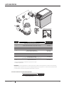
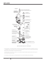
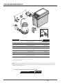
9
Key No. Part Description Part Number
1 DC Backup Pump PS17-2005*
2 1-1/4 FNPT x 1-1/2 Slip Elbow U78-1012
3 Float Switch PS17-2003
4 Charger/Controller PS217-1522
5 Battery Case Base
Battery Case Cover
PS17-2044
PS17-2045
6 AC Adaptor PS17-2008
7 Cable Ties - 11” **
8 Gateway Kit (Gateway, Power Supply, 1m RJ45 Cable) U117-1568
9 Switch Bracket PS17-2004
* If pump fails, replace entire system.
** Sold separately.
NOTICE: All check valves must be installed as described in the installation instructions or the warranty is
void. This includes the check valve for the primary sump pump in a Common Discharge installation.
Part Description Part Number
AGM 40A-Hour BAT40
Optional Batterry Supplies Sold Separately
PARTS LIST

17
FP979 (06-08-20)
WARRANTY
Retain Original Receipt for Warranty Eligibility
Limited Warranty
This Limited Warranty is effective July 11, 2019 and replaces all undated warranties and warranties dated before July 11, 2019.
Pentair Flotec* warrants to the original consumer purchaser (“Purchaser” or “You”) that its products are free from defects in material and
workmanship for a period of twelve (12) months from the date of the original consumer purchase. If, within twelve (12) months from the original
consumer purchase, any such product shall prove to be defective, it shall be repaired or replaced at Pentair Flotec’s option, subject to the terms
and conditions set forth herein. Note that this limited warranty applies to manufacturing defects only and not to ordinary wear and tear. All
mechanical devices need periodic parts and service to perform well. This limited warranty does not cover repair when normal use has exhausted
the life of a part or the equipment.
The original purchase receipt and product warranty information label are required to determine warranty eligibility. Eligibility is based on purchase
date of original product – not the date of replacement under warranty. The warranty is limited to repair or replacement of original purchased
product only, not replacement product (i.e. one warranty replacement allowed per purchase). Purchaser pays all removal, installation, labor,
shipping, and incidental charges.
Claims made under this warranty shall be made by returning the product (except sewage pumps, see below) to the retail outlet where it was
purchased immediately after the discovery of any alleged defect. Pentair Flotec will subsequently take corrective action as promptly as reasonably
possible. No requests for service will be accepted if received more than 30 days after the warranty expires.
Warranty is not transferable and does not apply to products used in commercial/rental applications.
For parts or troubleshooting assistance, DO NOT return product to your retail store - contact Pentair Flotec Customer Service at 1-800-365-6832.
Sewage Pumps
DO NOT return a sewage pump (that has been installed) to your retail store. Sewage pumps that have seen service and been removed carry a
contamination hazard with them.
If your sewage pump has failed:
• Wear rubber gloves when handling the pump;
• For warranty purposes, return the pump’s cord tag and original receipt of purchase to the retail store;
• Dispose of the pump according to local disposal ordinances.
Contact Pentair Flotec Customer Service at 1-800-365-6832.
Exceptions to the Twelve (12) Month Limited Warranty
Product Warranty Period
Parts2O* (Parts & Accessories), FP0F360AC, FP0FDC 90 days
FP0S1775A, FP0S4100X, FPPSS3000, FPCC5030, FPCI3350, FPCI5050, FPDC30 2 Years
4” Submersible Well Pumps, FPSC1725X, FPSE3601A, FPSC3350A, FPZT7300, FPZT7350, FPZT7450, FPZT7550 3 Years
FP7100 Series Pressure Tanks, E3305TLT, E3375TLT, E5005TLTT, E50TLT, E50VLT, E75STVT,
E75VLT, FPSE9000, FPSE9050
5 Years
General Terms and Conditions; Limitation of Remedies
You must pay all labor and shipping charges necessary to replace product covered by this warranty. This warranty does not apply to the following:
(1) acts of God; (2) products which, in the sole judgment of Pentair Flotec, have been subject to negligence, abuse, accident, misapplication,
tampering, or alteration; (3) failures due to improper installation, operation, maintenance or storage; (4) atypical or unapproved application, use
or service; (5)failures caused by corrosion, rust or other foreign materials in the system, or operation at pressures in excess of recommended
maximums.
This warranty sets forth the sole obligation of Pentair Flotec, and purchaser’s exclusive remedy for defective products.
PENTAIR FLOTEC SHALL NOT BE LIABLE FOR ANY CONSEQUENTIAL, INCIDENTAL, OR CONTINGENT DAMAGES WHATSOEVER.
THE FOREGOING WARRANTIES ARE EXCLUSIVE AND IN LIEU OF ALL OTHER EXPRESS AND IMPLIED WARRANTIES, INCLUDING BUT NOT
LIMITED TO THE IMPLIED WARRANTIES OF MERCHANTABILITY AND FITNESS FOR A PARTICULAR PURPOSE. THE FOREGOING WARRANTIES
SHALL NOT EXTEND BEYOND THE DURATION PROVIDEDHEREIN.
Some states do not allow the exclusion or limitation of incidental or consequential damages or limitations on how long an implied warranty lasts,
so the above limitations or exclusions may not apply to You. This warranty gives You specific legal rights and You may also have other rights which
vary from state to state.
293 Wright Street | Delavan, WI 53115 | United States | Phone: 800.365.6832 | Fax: 800.526.3757 | pentair.com/flotec

pentair.com
FP979 (08-06-20) ©2020. Tous droits réservés.
MANUEL D’INSTALLATION
ET D’UTILISATION
Systèmes de secours à batterie
FPDC 30
Pump Activity
Activité de pompe
Actividad de la bomba
System Alert
Alerte du système
Alerta del sistema
AC Power
Courant AC
CA
Charging
Recharge
En carga
Battery Status
État de batterie
Estado de la batería
Alarm Silenced
Alarme arrêtée
Alarma apagada
Test System
Tester
Probar sistema
Silence Alarm
Arrêter l’alarme
Apagar alarma
Light
Lumière
Luz
Circuit Breaker
Disjoncteur
Disyuntor
Pump
Pompe
Bomba
Float Switch
Interrupteur à otteur
Interruptor del otador
Power
Courant
Encendido
Reset System
Réinitialise
Restrablecer sistema
+

19
FP979 (06-08-20)
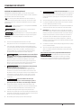
TABLE DES MATIÈRES
SECTION .......................................................................................................................................................................................................................PAGE
Renseignements relatifs à la sécurité ...................................................................................................................................................................... 20
Renseignements généraux .......................................................................................................................................................................................21
Conguration de la connexion Internet et des alertes ............................................................................................................................................. 22
Installation ................................................................................................................................................................................................................ 23
Fonctionnement ....................................................................................................................................................................................................... 29
Dépannage ................................................................................................................................................................................................................ 32
Liste des pièces ........................................................................................................................................................................................................ 33
Garantie ..................................................................................................................................................................................................................... 34

20
FP979 (06-08-20)
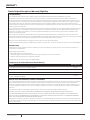
IMPORTANTES CONSIGNES DE SÉCURITÉ
CONSERVEZ CES INSTRUCTIONS – Ce manuel comporte des
consignes importantes qui doivent être suivies lors de l’installation,
de l’utilisation et de l’entretien du produit.
Ceci est le symbole d’alerte de sécurité. Si vous voyez ce
symbole sur votre pompe ou dans ce manuel, recherchez l’un des
mots d’avertissement ci-dessous et faites attention aux risques
de blessures!
indique un danger qui, s’il n’est pas évité, entraînera
la mort ou des blessures graves.
indique un danger qui, s’il n’est pas évité,
peut entraîner la mort ou des blessures graves.
indique un danger qui, s’il n’est pas évité, peut ou
pourrait entraîner des blessures légères ou moyennement graves.
REMARQUE: concerne des pratiques non liées aux lésions
corporelles.
Conservez les étiquettes de sécurité en bon état.
Remplacez-les si elles sont manquantes ou endommagées.
Pour éviter tout risque de blessures graves causées par un
choc électrique ou par des brûlures, ainsi que des dommages
matériels en raison d’une inondation, lisez attentivement
et suivez toutes les instructions de sécurité figurant dans
ce manuel et sur la pompe avant d’installer la pompe.
L’acide de batterie est corrosif. Évitez
les éclaboussures sur la peau, les vêtements ou le chargeur
de batterie. Portez un équipement de protection pour les yeux
et la tête lorsque vous manipulez la batterie. Branchez et
débranchez les bornes de sortieCC uniquement après avoir
débranché le chargeur de la prise de courantCA. Ne laissez
jamais les bornes de courant continu(CC) se toucher.
Tension dangereuse. Peut provoquer
un choc électrique grave ou mortel. Ne branchez ou ne
débranchez pas le chargeur de batterie lorsque vous vous
trouvez sur un plancher mouillé ou dans l’eau. Assurez-vous
de garder une main libre lorsque vous branchez ou débranchez
le chargeur. Si le plancher du sous-sol est mouillé, coupez
l’alimentation électrique du sous-sol avant de marcher sur
le plancher.
Risque d’inondation. Ne faites pas
fonctionner la pompe à sec. Cela endommage les joints et
pourrait provoquer des fuites et des dommages matériels.
Conformez-vous aux codes de plomberie et d’électricité
lorsque vous installez le système. Il est recommandé d’utiliser
un disjoncteur différentiel de fuite à la terre (DDFT) lors de
l’utilisation d’un appareil électrique immergé sous l’eau.
N’utilisez ce système que comme pompe de puisard de secours
à utilisation résidentielle. Ce système n’est pas conçu pour être
utilisé comme pompe de puisard principale.
Ne soulevez pas la pompe par le cordon électrique.
Risque de choc électrique. Ne soulevez
pas la pompe par le cordon électrique, soulevez-la uniquement
par le tuyau d’évacuation, l’anneau de levage ou la poignée de
la pompe. Soulever la pompe par le cordon peut endommager
ce dernier.
Utilisez cette pompe uniquement pour pomper de l’eau claire.
La pompe est dotée d’une lubrification permanente installée
en usine. N’essayez pas de la lubrifier!
Gardez le chargeur de batterie et le compartiment de batterie
à l’écart du plancher, dans un endroit sec, frais et bien aéré.
REMARQUE: Si un détecteur de monoxyde de carbone(CO)
est installé, il doit se situer à au moins 15pieds du chargeur de
batterie pour éviter les fausses alarmes. Pour obtenir de plus
amples renseignements, veuillez consulter les instructions
d’installation de votre détecteur de monoxyde de carbone.
Pour éviter les risques d’incendie ou d’explosion, gardez la
batterie loin de sources étincelles et de flammes (par exemple,
un brûleur de veilleuse).
La distance verticale maximale de pompage est de 4,6m (15pi)
pour le modèle FPDC30.
Assurez-vous que la pompe de puisard ne contient pas de
débris. Les débris peuvent endommager la pompe et causer
des inondations.
Avertissement concernant la proposition 65 de la Californie
Ce produit et les accessoires connexes
contiennent des produits chimiques considérés par l’État de
la Californie comme pouvant causer le cancer, des anomalies
congénitales ou d’autres troubles du système reproducteur.
CONSIGNES DE SÉCURITÉ
La page est en cours de chargement...
La page est en cours de chargement...
La page est en cours de chargement...
La page est en cours de chargement...
La page est en cours de chargement...
La page est en cours de chargement...
La page est en cours de chargement...
La page est en cours de chargement...
La page est en cours de chargement...
La page est en cours de chargement...
La page est en cours de chargement...
La page est en cours de chargement...
La page est en cours de chargement...
La page est en cours de chargement...
La page est en cours de chargement...
La page est en cours de chargement...
La page est en cours de chargement...
La page est en cours de chargement...
La page est en cours de chargement...
La page est en cours de chargement...
La page est en cours de chargement...
La page est en cours de chargement...
La page est en cours de chargement...
La page est en cours de chargement...
La page est en cours de chargement...
La page est en cours de chargement...
La page est en cours de chargement...
La page est en cours de chargement...
La page est en cours de chargement...
La page est en cours de chargement...
La page est en cours de chargement...
La page est en cours de chargement...
-
 1
1
-
 2
2
-
 3
3
-
 4
4
-
 5
5
-
 6
6
-
 7
7
-
 8
8
-
 9
9
-
 10
10
-
 11
11
-
 12
12
-
 13
13
-
 14
14
-
 15
15
-
 16
16
-
 17
17
-
 18
18
-
 19
19
-
 20
20
-
 21
21
-
 22
22
-
 23
23
-
 24
24
-
 25
25
-
 26
26
-
 27
27
-
 28
28
-
 29
29
-
 30
30
-
 31
31
-
 32
32
-
 33
33
-
 34
34
-
 35
35
-
 36
36
-
 37
37
-
 38
38
-
 39
39
-
 40
40
-
 41
41
-
 42
42
-
 43
43
-
 44
44
-
 45
45
-
 46
46
-
 47
47
-
 48
48
-
 49
49
-
 50
50
-
 51
51
-
 52
52


Flotec FPDC30 Le manuel du propriétaire
- Catégorie
- Pompes à eau
- Taper
- Le manuel du propriétaire
dans d''autres langues
- English: Flotec FPDC30 Owner's manual
- español: Flotec FPDC30 El manual del propietario
Documents connexes
Autres documents
-
Hydromatic FG-3100RF Le manuel du propriétaire
-
-
Simer A5300 Battery Backup System Le manuel du propriétaire
-
-
-
-
Pentair Home SSPC Sump Pump Controller Mode d'emploi
-
red lion RL-SPBS Le manuel du propriétaire
-
 Invert Halo Too Le manuel du propriétaire
