Signature Kitchen Suite SKSDV3002S Guide d'installation
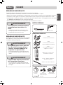
- Taper
- Guide d'installation

INSTALLATION GUIDE
ELECTRIC CONVECTION BUILT-IN OVEN
MFL51224811_01
www.signaturekitchensuite.ca
SKSSV3001S
SKSDV3002S
SKSCV3002S
ENGLISH FRANÇAIS
Copyright © 2021 - 2022 Signature Kitchen Suite. All Rights Reserved.

- 2 -
SAFETYPart 1
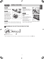
1BEFORE BEGINNING
Remove all tape and packing materials before using the oven. Dispose of all plastic bags after unpacking
the oven.
Never allow children to play with packing materials.
You can download an installation manual at www.signaturekitchensuite.ca
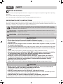
IMPORTANT SAFETY INSTRUCTIONS
Read and follow all instructions before using the oven to prevent the risk of fire, electric shock, injury to
persons, or damage when using the oven. This guide does not cover all possible conditions that may occur.
For further assistance contact the service agent or manufacturer.
This is the safety alert symbol. This symbol alerts you to potential hazards that can kill or hurt you
and others. All safety messages will follow the safety alert symbol and either the word “WARNING”
or “CAUTION”. These words mean :
WARNING
This symbol will alert you to hazards or unsafe practices which could cause serious
bodily harm or death.
CAUTION
This symbol will alert you to hazards or unsafe practices which could cause bodily
injury or property damage.
• The information in this manual should be followed exactly.
- Failure to do so could result in fire or electrical shock, causing property damage, personal
injury or death.
• DO NOT put any weight on the oven door. Never allow anyone to climb, sit, stand
or hang on the oven door.
- The oven could be tipped and injury might result from contact with hot food or the oven itself.
• The electrical power must be shut off while the electrical connections are being
made.
- Failure to do so can result in severe personal injury, death or electrical shock.
• New branch-circuit installations (1996 NEC), mobile homes, recreational vehicles,
or installations where local codes prohibit grounding through the neutral
conductor require 4-wire branch-circuit connection.
• Improper connection of aluminum house wiring to copper leads can result in
an electrical hazard or fire. Use only connectors designed for joining copper to
aluminum and follow the manufacturer’s recommended procedure closely.
• Mounting screws must be used.
- Failure to do so can result in the oven falling out of the cabinet causing serious injury.
WARNING
• Make sure the cabinets and wall coverings around the oven can withstand the
temperature (up to 194˚F[90˚C]) generated by the oven.
- Discoloration, delamination or melting may occur.
• DO NOT remove spacers on the side walls of the built-in oven.
- These spacers center the oven in the space provided.The oven must be centered to prevent
excess heat buildup that may result in heat damage or fire.
• DO NOT block the oven air exhaust located at the bottom of the oven.
- Blocking the exhaust may cause cabinet damage and product malfunction.
CAUTION

- 3 -
ENGLISH
SAFETYPart 1
IMPORTANT NOTE
This installation must be completed by a qualified installer or technician.
•Please read the entire Installation Instructions prior to installation.
•Remove all packing materials from the oven compartments before connecting the electrical supply to the oven.
•Installer: please retain these instructions for local inspector’s reference, then leave them with the consumer.
•Consumer: please read and keep these instructions for future reference and be sure to read the entire
OWNER’S MANUAL prior to use.
•Do not use any parts except for provided components when you install the product.
IMPORTANT NOTE
Proper installation is the responsibility of the installer,
and product failure due to improper installation is
NOT covered under warranty.
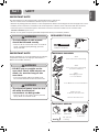
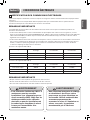
REQUIRED TOOLS
Phillips Screwdriver Drill
•The information in this manual
should be followed exactly.
−Failure to do so could result in fire or electrical
shock, causing property damage, personal
injury or death.
WARNING
•DO NOT put any weight on the
oven door. Never allow anyone to
climb, sit, stand or hang on the
oven door.
−The oven could tip and injury might result
from contact with hot food or the oven itself.
WARNING
•The electrical power must be shut
off while the electrical
connections are being made.
−Failure to do so can result in severe personal
injury, death or electrical shock.
WARNING
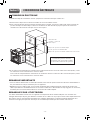
MATERIALS NEEDED
Junction Box Wire Nuts
36” (91 cm)
of String
3/4” Conduit
Connector
MATERIALS INCLUDED
4X14
6 Wood Screws for Mounting
4X24
6 Wood Screws for Mounting
(for Flush Installation)
Cover Brackets for Flush Installation
4X10 2 Screws
for bottom decorative trim
Bottom decorative trim
4X22
Self-Tapping Screws
for Cover Bracket

- 4 -
INSTALLATION REQUIREMENTSPart 2
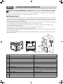
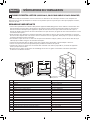
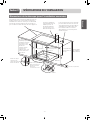
1INSTALLATION DRAWINGS
(SKSSV3001S, FOR 30” SINGLE BUILT-IN OVEN)
The first step of the installation is to measure the current cutout dimensions and compare them to the cutout
dimensions shown below. Little or no cabinet work may be necessary.
IMPORTANT NOTE
•The cabinet base platform must be able to support 190 lbs (86 kg). If the cabinet does not have a solid bottom,
two braces or runners must be installed level with the bottom of the cutout to support the weight of the oven.
Make sure the base is level and the front of the cabinet is square. If the cabinet base is not level, the oven racks
will tend to slide out when opening the door.
•If marks, blemishes or the cutout opening are visible above the installed oven, it may be necessary to add wood
shims under the runners and front trim until the marks or opening are covered.
•If the cabinet does not have a front frame and the sides are less than 3/4” (1.9 cm) thick, shim both sides
equally to establish the cutout width.
•The junction box must be flush with the rear wall of the cabinet as shown below.
•Allow at least a 23” clearance for the door depth when it is open.
•Kitchen cabinets in contact with the oven must be heat resistant up to 194°F (90°C), and fronts of nearby units
up to at least 158°F (70°C).
•Do not remove the gliding racks from the base packing. Gliding racks are attached separately to the top and
bottom of the oven.
H
G
D
E
F
A
B
C
J
I
K
N
P
M
O
Q
L
a
Conduit opening
b Circuit breaker
-Dimensions Single Oven
A Height 29 7/16” (747 mm)
B Width 29 3/4” (755 mm)
C Depth 23 3/8” (593 mm)
D Height (standard installation) 29” (736 mm)
E Height (power cord) 27 1/2" (699.5mm)
F Length (power cord) 60” (1524 mm)
G Width (back) 27 3/8” (695.3 mm)
H Width (standard installation) 28 3/7” (722 mm)
I Cabinet width 30” (762 mm)
J Overlap of oven 1” (25.4 mm)
K Cutout width 28 1/2” Min. (723.9 mm), 28 5/8” Max. (727 mm)
L Depth of open door 23” (584.2 mm)
M Cutout height 29 1/8” Min. (740 mm), 29 3/16” Max. (741.4 mm)
N Cutout depth 24” Min. (610 mm)
O Cutout location from floor 31” (787.4 mm)
P Height of conduit opening from floor of cutout 23 1/2” (596.9 mm)
Q Distance of conduit opening from side of cabinet 5” (127mm)

- 5 -
ENGLISH
Part 2 INSTALLATION REQUIREMENTS
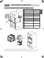
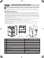
Cutout Dimensions (Flush)
I
H
M
G
L
DE
F
K
C
J
N
Cleat
(Spacer)
a
Conduit opening
b Circuit breaker
- Dimensions Single Oven
C Cutout width 30” (762 mm)
D Cleat (spacer) inset from front
of cabinet
1 3/8” (34.8mm)
E Cleat (spacer) width 3/16” (5 mm)
F Cleat (spacer) depth 1” (25.4 mm)
G Depth of open door 23” (584.2 mm)
H Bottom of cutout from floor 31” (787.4mm)
I Cutout depth 25” (635.0 mm)
J Cleat (spacer) height 29 5/8” (752.4 mm)
K Cutout height 28 9/16” (726 mm)
L Height of conduit opening from
floor of cutout
23 1/2” (596.9 mm)
M Distance of conduit opening
from side of cabinet
5” (127mm)
N Bottom of bottom decorative
trim to vent opening
3/4” (19 mm)
Cover Bracket
4X22
Tapping Screw
•The provided cover brackets are only used for flush cabinet installations.
•Remove one screw from the left and right sides as shown. These screw holes will be used to mount the cover
brackets. Install the cover brackets on the sides of the oven with the provided self-tapping screws.

- 6 -
Part 2 INSTALLATION REQUIREMENTS
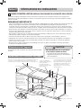
2INSTALLATION DRAWINGS
(SKSSV3001S, FOR 30" SINGLE BUILT-IN OVEN UNDERCOUNTER)
The first step of the installation is to measure the current cutout dimensions and compare them to the cutout
dimensions shown below. Little or no cabinet work may be necessary.
IMPORTANT NOTE
•The cabinet base platform must be able to support 190lbs (86kg). If the cabinet does not have a solid bottom,
two braces or runners must be installed level with the bottom of the cutout to support the weight of the oven.
Make sure the base is level and the front of the cabinet is square. If the cabinet base is not level, the oven racks
will tend to slide out when opening the door.
•If marks, blemishes or the cutout opening are visible above the installed oven, it may be necessary to add wood
shims under the runners and front trim until the marks or opening are covered.
•If the cabinet does not have a front frame and the sides are less than 3/4” (1.9 cm) thick, shim both sides
equally to establish the cutout width.
•The junction box must be flush with the rear wall of the cabinet as shown below.
•This oven is only approved to be installed under the specific models as labeled on this unit.
•Kitchen cabinets in contact with the oven must be heat resistant up to 194°F (90°C), and fronts of nearby units
up to at least 158°F (70°C).
•Do not remove the gliding racks from the base packing. Gliding racks are attached separately to the top and
bottom of the oven.
Product Dimensions
Dimensions are the same as the single built-in oven.
Cutout Dimensions
Gas and electrical connections for
30” (762 mm) gas cooktop must be located
in an adjacent accessible location to the
right. For a 36” (914 mm) gas cooktop, the
connections may be made to the left.
Gas or electric cooktops may be installed over this oven.
See cooktop installation instructions for cutout size.
See label on top of oven for approved cooktop models. 240 V / 208 V
Junction box location 3"ø
hole required (Junction box
may be in adjacent cabinet)
Cabinet
5”
25” (635 mm)
29 1/8” (740 mm) Min.
29 3/16” (741.4 mm) Max.
Allow 11/16” (17 mm)
overlap top of oven,
1
1/16” (17 mm) overlap
side edges of cutout
Top and/or side fillers
may be necessary if
unit is positioned
between existing
cabinets. Be sure they
are attached securely
since, they will anchor
the oven in the cabinet.
36” (914 mm)
Typical
Countertop
Height
23 1/2” (596.9 mm)
from the cutout
base
24” (610 mm)
2
3/4
”(70 mm) ~ 4”(102 mm)
28 1/2” (723.9 mm) Min.
28 5/8” (727 mm) Max.
•DO NOT block the oven air exhaust
located at the bottom of the oven.
−Blocking the exhaust may cause cabinet
damage and product malfunction.
CAUTION

- 7 -
ENGLISH
Part 2 INSTALLATION REQUIREMENTS
Cutout Dimensions (Flush)
Gas and electrical connections for
30” (762 mm) gas cooktop must be located
in an adjacent accessible location to the
right. For a 36” (914 mm) gas cooktop, the
connections may be made to the left.
Gas or electric cooktops may be installed over this oven.
See cooktop installation instructions for cutout size.
See label on top of oven for approved cooktop models. 240 V / 208 V
Junction box location
3"ø hole required
(Junction box may be
in adjacent cabinet)
Cabinet
5”
29 5/8” (752.4 mm) Allow 11/16” (17 mm)
overlap top of oven
Top and/or side fillers
may be necessary if
unit is positioned
between existing
cabinets. Be sure they
are attached securely
since, they will anchor
the oven in the cabinet.
36” (914 mm)
Typical
Countertop
Height
23 1/2” (596.9mm)
from the cutout
base
25”
(635 mm)
2
3/4
”(70 mm) ~ 4”(102 mm)
30” (762 mm)
3/4" (1.9 cm) bottom of
bottom decorative trim
to vent opening
1 3/8" (3.5 cm) cleat
(spacer) inset from
front of cabinet

- 8 -
Part 2 INSTALLATION REQUIREMENTS
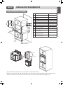
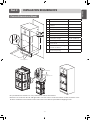
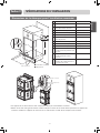
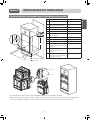
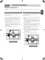
3INSTALLATION DRAWINGS
(SKSDV3002S, FOR 30” DOUBLE BUILT-IN OVEN)
The first step of the installation is to measure the current cutout dimensions and compare them to the cutout
dimensions shown below. Little or no cabinet work may be necessary.
IMPORTANT NOTE
•The cabinet base platform must be able to support 325lbs (147kg). If the cabinet does not have a solid bottom,
two braces or runners must be installed level with the bottom of the cutout to support the weight of the oven.
Make sure the base is level and the front of the cabinet is square. If the cabinet base is not level, the oven racks
will tend to slide out when opening the door.
•If marks, blemishes or the cutout opening are visible above the installed oven, it may be necessary to add wood
shims under the runners and front trim until the marks or opening are covered.
•If the cabinet does not have a front frame and the sides are less than 3/4” (1.9 cm) thick, shim both sides
equally to establish the cutout width.
•The junction box must be flush with the rear wall of the cabinet as shown below.
•Allow at least a 23” clearance for the door depth when it is open.
•Kitchen cabinets in contact with the oven must be heat resistant up to 194°F (90°C), and fronts of nearby units
up to at least 158°F (70°C).
•Do not remove the gliding racks from the base packing. Gliding racks are attached separately to the top and
bottom of the oven.
H
G
Q
LN
P
M
JI
K
O
F
D
E
A
BCa
Conduit opening
b Circuit breaker
-Dimensions Double Oven
A Height 52 1/16" (1323 mm)
B Width 29 3/4” (755 mm)
C Depth 23 3/8” (593 mm)
D Height (standard installation) 51 9/16” (1310 mm)
E Height (power cord) 50 5/16" (1277.2 mm)
F Length (power cord) 60” (1524 mm)
G Width (back) 27 3/8” (695.3 mm)
H Width (standard installation) 28 3/7” (722 mm)
I Cabinet width 30” (762 mm)
J Overlap of oven 1” (25.4 mm)
K Cutout width 28 1/2” Min. (723.9 mm), 28 5/8” Max. (727 mm)
L Depth of open door 23” (584.2 mm)
M Cutout height 51 13/16” Min. (1316 mm), 51 15/16” Max. (1319.2 mm)
N Cutout depth 24” Min. (610 mm)
O Cutout location from floor 12” (304.8 mm)
P Height of conduit opening from floor of cutout 47” (1193.8 mm)
Q Distance of conduit opening from side of cabinet 5” (127 mm)

- 9 -
ENGLISH
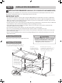
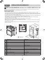
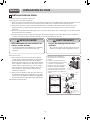
Part 2 INSTALLATION REQUIREMENTS
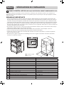
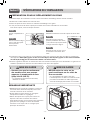
Cutout Dimensions (Flush)
M
G
H
I
L
J
D
F
C
E
K
N
Cleat (Spacer)
- Dimensions Double Oven
C Cutout width 30” (762 mm)
D Cleat (spacer) inset from front
of cabinet
1 3/8” (34.8 mm)
E Cleat (spacer) width 3/16” (5 mm)
F Cleat (spacer) depth 1” (25.4 mm)
G Depth of open door 23” (584.2 mm)
H Bottom of cutout from floor 12” (304.8mm)
I Cutout depth 25” (635.0 mm)
J Cleat (spacer) height 52 5/16" (1329 mm)
K Cutout height 51 9/32” (1303 mm)
L Height of conduit opening from
floor of cutout
47” (1193.8 mm)
M Distance of conduit opening
from side of cabinet
5” (127 mm)
N Bottom of bottom decorative
trim to vent opening
3/4” (19 mm)
Cover Bracket
4X22
Tapping Screw
•The provided cover brackets are only used for flush cabinet installations.
•Remove one screw from the left and right sides as shown. These screw holes will be used to mount the cover
brackets. Install the cover brackets on the sides of the oven with the provided self-tapping screws.

- 10 -
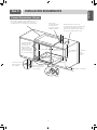
Part 2 INSTALLATION REQUIREMENTS
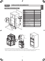
4INSTALLATION DRAWINGS
(SKSCV3002S, FOR 30” MICROWAVE COMBINATION WALL OVEN)
The first step of the installation is to measure the current cutout dimensions and compare them to the cutout
dimensions shown below. Little or no cabinet work may be necessary.
IMPORTANT NOTE
•The cabinet base platform must be able to support 202 lbs (91.65 kg). If the cabinet does not have a solid
bottom, two braces or runners must be installed level with the bottom of the cutout to support the weight of the
oven. Make sure the base is level and the front of the cabinet is square. If the cabinet base is not level, the oven
racks will tend to slide out when opening the door.
•If marks, blemishes or the cutout opening are visible above the installed oven, it may be necessary to add wood
shims under the runners and front trim until the marks or opening are covered.
•If the cabinet does not have a front frame and the sides are less than 3/4” (1.9 cm) thick, shim both sides
equally to establish the cutout width.
•The junction box must be flush with the rear wall of the cabinet as shown below.
•Allow at least a 23” clearance for the door depth when it is open.
•Kitchen cabinets in contact with the oven must be heat resistant up to 194°F (90°C), and fronts of nearby units
up to at least 158°F (70°C).
•Do not remove the gliding racks from the base packing. Gliding racks are attached separately to the top and
bottom of the oven.
F
H
G
Q
L
O
N
P
M
JI
K
E
D
A
C
B
a
Conduit opening
b Circuit breaker
-Dimensions Single Oven
A Height 43 13/16" (1113 mm)
B Width 29 3/4" (755 mm)
C Depth 23 3/8" (593 mm)
D Height (standard installation) 43 3/16” (1097 mm)
E Height (power cord) 27 3/16" (690 mm)
F Length (power cord) 60” (1524 mm)
G Width (back) 27 3/8” (695.3 mm)
H Width (standard installation) 28 3/7” (722 mm)
I Cabinet width 30” (762 mm)
J Overlap of oven 1” (25.4 mm)
K Cutout width 28 1/2” Min. (723.9 mm), 28 5/8” Max. (727 mm)
L Depth of open door 23”(584.2 mm)
M Cutout height 43 7/16” Min. (1103 mm), 43 1/2” Max. (1106 mm)
N Cutout depth 24” Min. (610 mm)
O Cutout location from floor 12” (304.8 mm)
P Height of conduit opening from floor of cutout 39 7/8” (1012.8 mm)
Q Distance of conduit opening from side of cabinet 5” (127mm)

- 11 -
ENGLISH
Part 2 INSTALLATION REQUIREMENTS
Cutout Dimensions (Flush)
M
G
H
I
L
J
D
F
C
E
K
N
Cleat (Spacer)
- Dimensions Combi Oven
C Cutout width 30” (762 mm)
D Cleat (spacer) inset from front
of cabinet
1 3/8” (34.8mm)
E Cleat (spacer) width 13/64” (5 mm)
F Cleat (spacer) depth 1” (25.4 mm)
G Depth of open door 23” (584.2 mm)
H Bottom of cutout from floor 12” (304.8 mm)
I Cutout depth 25” (635.0 mm)
J Cleat (spacer) height 44” (1118 mm)
K Cutout height 43 13/16” (1113 mm)
L Height of conduit opening from
floor of cutout
39 7/8” (1012.8 mm)
M Distance of conduit opening
from side of cabinet
5” (127mm)
N Bottom of bottom decorative
trim to vent opening
3/4” (19 mm)
Cover Bracket
4X22
Tapping Screw
•The provided cover brackets are only used for flush cabinet installations.
•Remove one screw from the left and right sides as shown. These screw holes will be used to mount the cover
brackets. Install the cover brackets on the sides of the oven with the provided self-tapping screws.

- 12 -
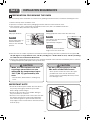
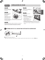
Part 2 INSTALLATION REQUIREMENTS
4. Place the oven on a table or platform even with the cutout opening. (The table or platform must support 190
lbs [86 Kg] for a single built-in oven, 325 lbs [147 Kg] for a double built-in oven, 202 lbs [91.65 kg]
for a Microwave Combination Wall Oven.)
5. Remove the metal bottom trim from the oven. It will be installed at the end of the installation process. The trim
is wrapped separately and taped to the top of the unit.
Step. 1
Fully open the door.
Hinge
lock
Slot
Lock
Unlock
Step. 2
Pull the hinge locks up
towards the door's
frame, to the unlocked
position.
Step. 3
Firmly grasp both sides of the door at the top.
Step. 4 about 5
Close door to the door removal
position, which is
approximately 5 degrees.
Step. 5
Lift door up and out until the
hinge arm is clear of the slot.
IMPORTANT NOTE
•Do not lift the door by the handle. The oven door is
very heavy. Firmly grasp the door by the sides
before lifting it off the hinges.
•Do not lay the oven door on its handle. Doing so
may cause dents or scratches.
•Use two or more people to lift or move the oven into
the cabinet opening. Use caution when lifting the
oven and wear gloves to protect hands from any
sharp edges. Failure to follow these instructions may
result in injury.
Spacer
5PREPARATION FOR MOVING THE OVEN
The second step of the installation is to remove any packing material from the oven before installing the oven.
1. Remove all tape from around the oven.
2. Open the oven door and remove packaging materials and oven racks inside the oven.
3. Door removal is not a requirement for installation of the oven, but is an added convenience.
To remove the door, follow the steps below.
•Make sure the cabinets and wall
coverings around the oven can
withstand the temperature (up to
194 °F [90 °C]) generated by the
oven.
−Discoloration, delamination or melting may
occur.
CAUTION
•DO NOT remove spacers on the
side walls of the built-in oven.
−These spacers center the oven in the space
provided. The oven must be centered to
prevent excess heat buildup that may result in
heat damage or fire.
CAUTION

- 13 -
ENGLISH
Part 3 ELECTRICAL CONNECTIONS
1ELECTRICAL CONNECTION REQUIREMENTS
The third step of the installation is to follow the electrical connection requirements below.
Ensure that dedicated circuit protection is prepared as recommended and that the oven is grounded properly.
IMPORTANT NOTE
Be sure the wall oven is installed and grounded properly by a qualified installer or service technician.
•This wall oven must be electrically grounded in accordance with local codes or, in their absence, with the
National Electrical Code ANSI/NFPA No.70- latest edition in United States, or with CSA Standard C22.1-1982 and
C22.2 No.01982 (or latest edition), Canadian Electrical Code, Part1, and all local codes and ordinances.
•This wall oven must be supplied with the proper voltage and frequency, and connected to an individual,
properly grounded branch circuit, protected by a circuit breaker or fuse. To know the circuit breaker or fuse
required by this model, see the rating plate to find the wattage consumption and refer to the table below to get
the circuit breaker or fuse amperage.
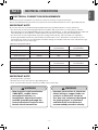
[Appliance rating Watts 240 V]
Category Power Consumption Protection circuit
recommended
Wire gauge
recommended
Single wall oven 6100 W 40 A 12 AWG
Double wall oven 10200 W 50 A 8 AWG
Combi wall oven 7800 W 40 A 10 AWG
[Appliance rating Watts 208 V]
Category Power Consumption Protection circuit
recommended
Wire gauge
recommended
Single wall oven 4600 W 30 A 12 AWG
Double wall oven 7700 W 50 A 8 AWG
Combi wall oven 6200 W 40 A 10 AWG
IMPORTANT NOTE
•Do Not ground to a gas pipe.
•Do Not have a fuse in the neutral or grounding circuit.
•A U.L.-listed conduit connector must be provided at the junction box.
•New branch-circuit installations
(1996 NEC), mobile homes,
recreational vehicles, or
installations where local codes
prohibit grounding through the
neutral conductor require 4-wire
branch-circuit connection.
WARNING
•Improper connection of aluminum
house wiring to copper leads can
result in an electrical hazard or
fire. Use only connectors designed
for joining copper to aluminum
and follow the manufacturer’s
recommended procedure closely.
WARNING

- 14 -
Part 3 ELECTRICAL CONNECTIONS
2ELECTRICAL CONNECTION
The fourth step of the installation is to prepare the electrical connection as follows:
1. Turn off the circuit breaker or remove fuses to the oven branch circuit.
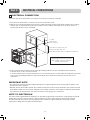
2. With the oven positioned directly in front of the cabinet opening, connect the flexible conduit to the electrical
junction box as shown below. Position the conduit in such a manner that it will lie on top of the oven in a
natural loop when the oven is installed.
Conduit
opening 3"ø
hole required
23 1/2” Min for single wall oven
42” Min for double wall oven
39 7/8” Min for Microwave Combination Wall Oven
Junction Box must be recessed
and conduit connector must be
used at Junction Box.
5” Min
3. If local codes permit connection of the frame grounding conductor to the neutral(white) wire, follow the
instructions for a 3-wire circuit connection.
If used in mobile homes or new construction, or a recreational vehicle, or local codes do not permit connection
of the frame grounding conductor to the neutral (white) wire, follow the instructions for a 4-wire circuit
connection.
IMPORTANT NOTE
•The wall ovens must be hard wired (direct wired) into an approved junction box. A plug and receptacle is not
permitted on these products.
• DO NOT shorten the flexible conduit. The conduit connector must be securely attached to the junction box and
the flexible conduit must be securely attached to the conduit connector. If the flexible conduit will not fit within
the connector, do not install the oven until a connector of the proper size is obtained.
NOTE TO ELECTRICIAN
The power leads supplied with the appliance are UL, CSA recognized for connection to larger gauge household
wiring. The insulation of these leads is rated at temperatures much higher than the temperature rating of
household wiring. The current carrying capacity of the conductor is governed by the wire gauge and the
temperature rating of the insulation around the wire.

- 15 -
ENGLISH
Part 3 ELECTRICAL CONNECTIONS
IMPORTANT NOTE
•You will need to purchase an appropriate conduit connector to complete the connection of the conduit to the
junction box.
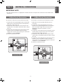
To connect to a three-wire circuit, follow these steps:
1. Connect the oven’s ground (green) wire and neutral
(white) wire to the branch circuit’s neutral (white or
gray) wire, using a wire nut.
2. Connect the oven’s red wire to the branch circuit’s
red (L2) wire in accordance with local codes, using a
wire nut.
3. Connect the oven’s black wire to the branch circuit’s
black (L1) wire in accordance with local codes,
using a wire nut. If the house wiring uses aluminum
conductors, see the WARNING.
4. Install the junction box cover.
Junction Box
White Green
Black
Red
Neutral
Wire nut
To connect to a four-wire circuit, follow these steps:
1. Separate the oven’s ground and white wires if
necessary.
2. Connect the oven’s ground (green) wire to the
branch circuit’s ground (green) wire in accordance
with local codes, using a wire nut. If the house
wiring uses aluminum conductors, see the
WARNING.
3. Connect the oven’s white wire to the branch circuit’s
neutral (white or gray in color) wire in accordance
with local codes, using a wire nut.
4. Connect the oven’s red wire to the branch circuit’s
red (L2) wire in accordance with local codes, using a
wire nut.
5. Connect the oven’s black wire to the branch circuit’s
black (L1) wire in accordance with local codes,
using a wire nut. If the house wiring uses aluminum
conductors, see the WARNING.
6. Install the junction box cover.
Junction Box
White
Green
Black
Red
Neutral
Wire nut
3-Wire Circuit Connection 4-Wire Circuit Connection

- 16 -
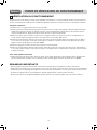
Part 4 INSTALL THE OVEN
1CABINET INSTALLATION
Install the oven into the cabinet as follows :
1. Sliding the oven into the opening.
a. Loop (do not tie) a 36” (91 cm) string around the conduit before the oven is slid into place. Lay the string
over the top of the oven and use it to keep the conduit from falling behind the oven.
b. Lift oven into cabinet cutout using the oven opening as a grip. Carefully push against the oven front frame.
Do not push against outside edges.
c. While sliding the oven back, pull the string so that the conduit lies on the top of the oven in a natural loop.
d. When you are sure the conduit is out of the way, slide the oven 3/4 of the way back into the opening.
Remove the string by pulling on one end of the loop.
•DO NOT block the oven air exhaust
located at the bottom of the oven.
−Blocking the exhaust may cause cabinet
damage and product malfunction.
CAUTION
•Mounting screws must be used.
−Failure to do so can result in the oven falling
out of the cabinet causing serious injury.
WARNING
2. Securing the oven.
a. Using the mounting holes on the oven side trim
as a guide, drill pilot holes for screws provided
(For securing the double wall oven, use a
minimum of 4 screws, one on each side in both
the upper and lower ovens. For securing the
single wall oven, use a minimum of 2 screws,
one on each side. For securing the Combi Oven,
use a minimum of 4 screws, one on each side in
both the upper and lower ovens.)
b. Secure the oven to the cabinet with screws
provided.
If the cabinet is particle board, you must use 3/4”
particle board screws. These may be purchased
at any hardware store.
3. Reinstall the oven door.
Mounting
Hole
Locations
Trim Screws Side Trim
Side Trim
Lower base
Metal Trim:
Correct
position
Metal Trim:
Wrong position
Metal
bottom
trim
1 4/9”
(1.1 cm)
- Ensure that the metal bottom
trim is correctly installed.
- When you install the oven door,
be carefull not to bump the
metal bottom trim.
- Keep oven vents unobstructed.
Replace the bottom trim if it
becomes bent or deformed.
Never block the vent with plastic
or heat-sensitive items.
Metal bottom
trim (Vent)
Mounting
Hole
Locations

- 17 -
ENGLISH
Part 4 INSTALL THE OVEN
Step. 1
Firmly grasp both sides
of the door at the top.
Step. 2
With the door at the
same angle as the
removal position, seat
the indentation of the
hinge arm into the
bottom edge of the
hinge slot. The notch
in the hinge arm must
be fully seated into the
bottom of the slot.
Step. 3
Fully open the door. If the door will not fully open, the
indentation is not seated correctly in the bottom edge
of the slot.
Step. 4
Push the hinge locks up
against the front frame of the
oven cavity to the locked
position.
Step. 5
Close the oven door.
NOTE
When you install the oven
door, be careful not to bump
the bottom vent trim.
Keep oven vents
unobstructed. Replace the
bottom vent trim if it
becomes bent or deformed. Never block the vent with
plastic or heat-sensitive items.
Hinge arm
Bottom
edge of
slot
Indentation
Hinge arm
Hinge lock
Bottom
vent trim
2ASSEMBLING THE BOTTOM DECORATIVE TRIM
a
Bottom decorative trim
•After installing the oven in the cabinet, assemble bottom decorative trim with 2 screws
b
(4X10).

- 18 -
OPERATION CHECKLISTPart 5
1CHECKING OPERATION
Each of the functions has been factory checked before shipping. However, it is suggested that you verify the
operation of the oven once more. Refer to the Owner’s Manual. Follow the instructions for the basic check.
Common
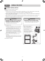
1. Turn on power supply. The initial signal sound will be heard.
2. Check the operation of the broil mode. When the oven is set to broil, the upper element in the oven should
become red. After a few minutes, partially open the oven door. You should feel heat from the oven. Adjust the
oven mode knob to OFF position.
3. Check the operation of the bake mode. After setting the oven to 350 °F / 177 °C for baking, the temperature of
the oven in the display should increase. Adjust the oven mode knob to OFF position.
4. Check the operation of the convection bake mode. After setting the oven to 350 °F / 177 °C for convection
baking, the fan inside the oven should come on with the door closed. Adjust the oven mode knob to OFF
position.
5. Turn on and off the oven light to check the lights are in normal condition.
6. Check the operation of the burner for each convection mode. After setting the oven to 350 °F / 177 °C for each
convection mode, the fan inside the oven should come on with door closed.
Combi Oven Only
1. Check the Microwave function. Place a glass bowl filled with water in upper oven. Turn the microwave on for 1
minute. The water should be hot. Adjust the oven mode knob to OFF
IMPORTANT NOTE
•A small amount of smoke and odor may be noticeable during the initial break-in period.
•If the oven does not operate properly or an F-, followed by a number, appears in the display, see the Owner’s
Manual for the troubleshooting list. The list includes common occurrences that are not the result of defective
workmanship or materials in this product. If the problem occurs continuously, contact the dealer.
•Refer to the warranty in the Owner’s Manual for the LG toll-free service number and address.

FOUR MURAL COMBINÉ
FOUR À CONVECTION ÉLECTRIQUE
ENCASTRÉ
MFL51224811_01
www.signaturekitchensuite.ca
SKSSV3001S
SKSDV3002S
SKSCV3002S
FRANÇAIS
Copyright © 2021 - 2022 Signature Kitchen Suite. Tous droits réservés.

- 2 -
SÉCURITÉ
Section 1
1ANTES DE COMENZAR
Retirez tous les rubans adhésifs et emballages avant d’utiliser le four. Jetez les sacs plastiques après avoir
déballé le four.
Ne laissez jamais les enfants jouer avec les emballages.
Vous pouvez télécharger le manuel d’installation au www.signaturekitchensuite.ca
IMPORTANTES CONSIGNES DE SÉCURITÉ
Lisez et suivez toutes les directives avant d’utiliser votre four afin d’éviter tout risque d’incendie, de choc
électrique, de blessure ou de dommage lors de l’utilisation du four. Ce manuel ne couvre pas tous les
risques pouvant survenir. Pour plus d’assistance, contactez votre agent de service ou le fabricant.
Ce symbole représente une alerte de sécurité. Ce symbole vous avise de dangers possibles pouvant causer
la mort, des blessures ou autres. Tous les messages de sécurité seront précédés du symbole d’alerte de
sécurité ainsi que des mots «AVERTISSEMENT» ou «MISE EN GARDE». Ces mots signifient :
AVERTISSEMENT
Ce symbole vous avertit des risques ou des pratiques dangereuses qui
pourraient causer de graves blessures, voire la mort.
MISE EN GARDE
Ce symbole vous avertit des risques ou des pratiques dangereuses qui
pourraient causer de graves blessures ou des dommages à la propriété.
• Les informations contenues dans ce manuel doivent être suivies à la lettre.
- Il pourrait en résulter un incendie ou un choc électrique pouvant causer des dommages à la propriété, des
blessures ou la mort.
• Ne JAMAIS appuyer sur la porte du four. Ne laisser personne grimper, s’asseoir, se mettre
debout ou se suspendre à la porte du four.
- Le four pourrait basculer causant des blessures par le déversement d’aliments ou par le four lui-même.
• L’appareil doit être hors tension lors des connections électriques.
- Le non-respect de ces règles peut entraîner de graves blessures corporelles, la mort ou un choc électrique.
• Il est nécessaire d’utiliser un câble à 4 conducteurs pour les nouvelles installations avec
alimentation par un circuit secondaire (NEC 1996) dans les résidences mobiles et les véhicules
récréatifs ou pour les installations où les codes locaux interdisent la mise à la terre par
l’intermédiaire d’un conducteur neutre.
• Une connexion incorrecte du câblage en aluminium à des fils en cuivre peut causer un risque
électrique ou un incendie. Utilisez seulement des connecteurs permettant de connecter le
cuivre à l’aluminium et suivez, avec soin, la procédure recommandée par le fabricant.
• Les vis de montage doivent être utilisées.
- En cas de non-respect de cette règle, le four peut tomber du meuble causant de graves blessures.
AVERTISSEMENT
• Assurez-vous que les revêtements des meubles et du mur peuvent supporter la température
du four (jusqu’à 90°C (194°F)).
- Les revêtements pourraient être décolorés, délaminés ou fondus.
• NE PAS retirer les cales sur les parois extérieures sur les côtés du four encastrable.
- Ces cales permettent de centrer le four dans l’ouverture prévue à son effet. Le four doit être centré pour
éviter l’accumulation de chaleur qui pourrait causer des dommages par la chaleur ou un incendie.
• NE PAS bloquer les évacuations d’air situées au bas du four.
- Le meuble pourrait être endommagé ou l’appareil mal fonctionner si les évacuations d’air sont bloquées.
MISE EN GARDE
La page est en cours de chargement...
La page est en cours de chargement...
La page est en cours de chargement...
La page est en cours de chargement...
La page est en cours de chargement...
La page est en cours de chargement...
La page est en cours de chargement...
La page est en cours de chargement...
La page est en cours de chargement...
La page est en cours de chargement...
La page est en cours de chargement...
La page est en cours de chargement...
La page est en cours de chargement...
La page est en cours de chargement...
La page est en cours de chargement...
La page est en cours de chargement...
La page est en cours de chargement...
La page est en cours de chargement...
La page est en cours de chargement...
La page est en cours de chargement...
-
 1
1
-
 2
2
-
 3
3
-
 4
4
-
 5
5
-
 6
6
-
 7
7
-
 8
8
-
 9
9
-
 10
10
-
 11
11
-
 12
12
-
 13
13
-
 14
14
-
 15
15
-
 16
16
-
 17
17
-
 18
18
-
 19
19
-
 20
20
-
 21
21
-
 22
22
-
 23
23
-
 24
24
-
 25
25
-
 26
26
-
 27
27
-
 28
28
-
 29
29
-
 30
30
-
 31
31
-
 32
32
-
 33
33
-
 34
34
-
 35
35
-
 36
36
-
 37
37
-
 38
38
-
 39
39
-
 40
40


Signature Kitchen Suite SKSDV3002S Guide d'installation
- Taper
- Guide d'installation
dans d''autres langues
Autres documents
-
LG LWS3081ST Manuel utilisateur
-
LG LWS3081ST Mode d'emploi
-
JennAir JJW2427LL Le manuel du propriétaire
-
KitchenAid KODC304ESS Manuel utilisateur
-
Whirlpool WOS52ES4MB Built In 24 Inch Single and Double Oven Manuel utilisateur
-
Whirlpool WOD52ES4MB Manuel utilisateur
-
KitchenAid KOSE900HBS Le manuel du propriétaire
-
Monogram ZEP30FRSS Manuel utilisateur
-
JennAir JMC6224HM Guide d'installation