Electrolux EFLS517SIW Guide d'installation
- Catégorie
- Sèche-linge électriques
- Taper
- Guide d'installation

EN FRONT LOAD WASHER
FR LAVEUSE Á CHARGEMENT FRONTAL
ES LAVADORA DE CARGA FRONTAL
INSTALLATION INSTRUCTIONS
INSTRUCTIONS D’INSTALLATION
INSTRUCCIONES DE INSTALACIÓN
A04615101A August 2015

2
2
Important Safety Instructions
©2015 Electrolux Major Appliances All rights reserved.
Recognize safety symbols, words
and labels
Safety items throughout this manual are
labeled with a WARNING or CAUTION
based on the risk type as described:
• Destroy the carton and plastic bags after the dryer is unpacked. Children might use them for play.
Cartons covered with rugs, bedspreads, or plastic sheets can become airtight chambers causing
suff ocation. Place all materials in a garbage container or make materials inaccessible to children.
• For your safety the information in this manual must be followed to minimize the risk of fi re or explo-
sion or to prevent property damage, personal injury or loss of life. Do not store or use gasoline or
other fl ammable vapors and liquids in the vicinity of this or any other appliance.
• Install the washer according to the manufacturer’s instructions and local codes.
• The electrical service to the washer must conform with local codes and ordinances and the latest
edition of the National Electrical Code, ANSI/NFPA 70, or in Canada, the Canadian electrical
code C22.1 part 1.
• To avoid back or other injury, have more than one person move or lift the washer.
• Do not stack a dryer on top of washer already installed on pedestal. Do not stack washer on top
of dryer. Do not stack washer on top of another washer.
• The instructions in this manual and all other literature included with this dryer are not meant to
cover every possible condition and situation that may occur. Good safe practice and caution
MUST be applied when installing, operating and maintaining any appliance.
Save these instructions for future reference.
Table of contents
WARNING
For your safety the information in this manual must be followed to minimize the risk of fi re or
explosion or to prevent property damage, personal injury or loss of life. Do not store or use
gasoline or other fl ammable vapors and liquids in the vicinity of this or any other appliance.
Important Safety Instructions .....................................2
Installation Requirements ........................................ 3-6
Unpacking Washer ......................................................7-8
Installation Instructions ...........................................9-10
Reversing Door ...........................................................11-14
Options .............................................................................. 15
WARNING
RISK OF FIRE - Read all of the following instructions before installing and using this appliance:
This symbol alerts you to situations that may
cause bodily injury or property damage.
This symbol alerts you to situations that may
cause serious body harm, death or property
damage.

3
NOTE
Hoses are not included with washer purchase.
See “Accessories” section for various inlet hose
kits to fi t your specifi c installation.
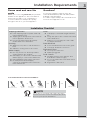
Installation Requirements
Tools and materials needed for installation:
Adjustable
pliers
Adjustable
wrench
3/8” or 10 mm
box wrench
OR OR OR AND AND
Ratchet and
socket set
Carpenter’s level
Optional
universal wrench
Please read and save this
guide
Thank you for choosing Electrolux, the premium
brand in home appliances. These Installation
Instructions are part of our commitment to
customer satisfaction and product quality
throughout the life of your new appliance.
Questions?
Installation Checklist
Drain
Stand pipe or wall drain height minimum
24”
Verify anti-siphon disc is attached toward
end of drain hose
Drain hose secured in place with cable
tie (shipped in drum)
Door Reversal
Follow detailed instructions in this guide
Test hinge and latch for function
Electrical Power
House power turned on
Washer plugged in
Final Checks
Installation Instructions and Use and
Care Guide read thoroughly
Door locks and water enters drum when
cycle starts
Registration card sent in
Shipping Hardware
Foam shipping support (under wash tub)
removed and stored
Shipping bolts and spacers removed from
rear of appliance and stored
Hole plugs (shipped in bag in drum)
installed in holes in backsheet
Leveling
Washer is level, side-to-side and front-to-
back
Cabinet is setting solid on all corners
Water Supply
Use only new hoses and verify rubber
sealing washers are installed
HOT supply is connected to HOT inlet and
COLD supply is connected to COLD inlet
HOT and COLD water supply turned on
No leaks present at water supply
connections or appliance inlet connections -
recheck in 24 hours
For toll-free telephone support in the U.S.:
1-877-4ELECTROLUX (1-877-435-3287) and in
Canada: 1-800-265-8352.
For online support and product information visit
www.electroluxappliances.com.
Inlet hose (x2)

4
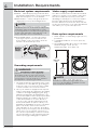
Installation Requirements
Electrical system requirements Water supply requirements
Grounding requirements
Drain system requirements
CIRCUIT - Individual, properly polarized and
grounded 15 amp. branch circuit fused with 15
amp. time delay fuse or circuit breaker.
POWER SUPPLY - 2 wire, with ground, 120 volt
single phase, 60 Hz, Alternating Current.
OUTLET RECEPTACLE - Properly grounded
3-prong receptacle to be located so the
power supply cord is accessible when the
washer is in an installed position.
type
type
Grounding
Grounding
receptacle
receptacle
wa
wa
ll
ll
Po
Po
wer cord
wer cord
with 3-prong
with 3-prong
gr
gr
ounded plug
ounded plug
Do not, under any circumstances,
Do not, under any circumstances,
cut, remove, or bypass the
cut, remove, or bypass the
grounding prong.
grounding prong.
1. The washer MUST be grounded. In the event
of malfunction or breakdown, grounding will
reduce the risk of electrical shock by a path
of least resistance for electrical current.
2. Since your washer is equipped with a power
supply cord having an equipment-grounding
conductor and a grounding plug, the plug
MUST be plugged into an appropriate, cop-
per wired receptacle that is properly installed
and grounded in accordance with all local
codes and ordinances or in the absence
of local codes, with the National Electrical
Codes, ANSI/NFPA 70 (latest edition), or in
Canada, the Canadian electrical code C22.1
part 1. If in doubt, call a licensed electri-
cian. DO NOT cut off or alter the grounding
prong on the power supply cord. In situations
where a two-slot receptacle is present, it is
the owner’s responsibility to have a licensed
electrician replace it with a properly ground-
ed three prong grounding type receptacle.
Hot and cold water faucets MUST be installed
within hose length of your washer’s water inlet.
The faucets MUST be 3/4 inch (1.9 cm) with
threading for laundry hose connection. Water
pressure MUST be between 30 and 120 psi.
Pressure diff erence between hot and cold can-
not be more than 10 psi. Your water department
can advise you of your water pressure.
1. Drain capable of eliminating 17 gals (64.3 L)
per minute.
2. A standpipe diameter of 1-1/4 in. (3.18 cm)
minimum.
3. The standpipe height above the fl oor should be:
Minimum height: 24 in. (61 cm)
Maximum height: 96 in. (244 cm)
96”
(244
cm)
max.
24”
(61
cm)
min.
NOTE
Because of potentially inconsistent voltage
capabilities, the use of this washer with power
created by gas powered generators, solar
powered generators, wind powered generators
or any other generator other than the local
utility company is not recommended.
NOTE
Drain hose length is 59 in. (150 cm). For
installations requiring a longer drain hose,
use hose P/N 137098000, available from an
authorized parts distributor.
WARNING
ELECTRICAL SHOCK HAZARD
Improper connection of the equipment
grounding conductor can result in a risk
of electrical shock. Check with a licensed
electrician if you are in doubt as to whether
the appliance is properly grounded.

5
Installation Requirements
MINIMUM INSTALLATION CLEARANCES - Inches (cm)
SIDES REAR TOP FRONT
Alcove 0” (0 cm) 0” (0 cm) 0” (0 cm) n/a
Under-
Counter
0” (0 cm) 0” (0 cm) 0” (0 cm) n/a
Closet 0” (0 cm) 0” (0 cm) 0” (0 cm) 1” (2.5 cm)
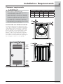
Clearance requirements
0”
(0
cm)
0”
(0
cm)
INSTALLATION IN A RECESS OR CLOSET
If washer and dryer are installed in the same
closet, door ventilation is required: A minimum
of 120 square inches (774.2 cm²) of opening,
equally divided at the top and bottom of the
door, is required. Louvered openings should
be located 3 inches (7.6 cm) from bottom
and top of door. Air openings are required to
be unobstructed when a door is installed. A
louvered door with equivalent air openings for
the full length of the door is acceptable.
60 sq. in.
(387.1cm²)
3”
(7.6cm)
60 sq. in.
(387.1cm²)
3”
(7.6cm)
closet door
IMPORTANT
DO NOT INSTALL YOUR WASHER:
1. ...in an area exposed to dripping water or
outside weather conditions.
2. ...in an area where gasoline or other fl am-
mables are kept or stored. If the washer is
installed in a garage, it must be a minimum
of 18 inches (45.7 cm) above the fl oor.
3. ...on carpet. Floor MUST be solid with a
maximum slope of 1 inch (2.5 cm). To mini-
mize vibration or movement, reinforcement
of the fl oor may be necessary.
1”
(2.5
cm)
0”
(0
cm)

6
Installation Requirements
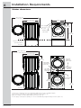
Washer dimensions
*Connection of water inlet hose on steam dryer adds 3/4 in. (2 cm) to installation depth.
1
Power supply cord length on washer approximately 60 inches (152.5 cm).
2
Drain hose length on washer approximately 59 inches (150 cm).
3
Power supply cord length on gas dryer or electric Canadian dryer approximately 60 inches (152.5 cm).
water supply
connection on
rear of unit
electrical
supply on
rear of unit
3
gas supply
pipe on rear
of gas unit
centerline
height for
rear vent
53.5” (136 cm)*
to clear open door
53.5” (136 cm)*
to clear open door
31.5” (79.5 cm)*
to front of closed door
31.5” (79.5 cm)*
to front of closed door
75.75”
(192.5 cm)
41.0”
(105 cm)
39.0”
(99 cm)
27.0”
(68.5 cm)
water supply
connection on
rear of unit
drain hose on
rear of unit
2
drain hose on
rear of unit
3
power cord on
rear of unit
1
power cord
on rear of
unit
1
fl oor line
fl oor line
fl oor line
freestand washer
on fl oor
washer mounted on
optional pedestal
38.0”
(96.5 cm)
53.25”
(135.5 cm)

7
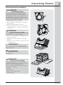
Unpacking Washer
Removing foam packaging
1. Temporarily remove door tape.
2. Open washer door and remove everything
from the drum.
3. Close door and reapply door tape.
4. Using a rug, blanket or piece of cardboard
to protect the fl oor, carefully lay the washer
on its back.
5. Remove styrofoam base and shipping plug
and set them aside.
6. Carefully return the washer to an upright
position.
7. Carefully move the washer to within 4 feet (1 m)
of its fi nal location.
WARNING
SUFFOCATION HAZARD
Destroy the carton and plastic bags after
the washer is unpacked. Children might use
them for play. Cartons covered with rugs,
bedspreads, or plastic sheets can become
airtight chambers causing suff ocation. Place
all materials in a garbage container or make
materials inaccessible to children.
CAUTION
EXCESSIVE WEIGHT HAZARD
To avoid back or other injury, have more than
one person move or lift the washer.
IMPORTANT
Save styrofoam base and shipping plug for
use to help prevent washer damage during
any future moves.
IMPORTANT
Do NOT tip washer upside down onto its top
for any reason.
WARNING
ELECTRICAL SHOCK HAZARD
Certain internal parts are intentionally not
grounded and may present a risk of electrical
shock if contacted during installation.
Do not contact the following parts while the
appliance is energized:
● Pump
● Drive motor
● Electrical control boards
● Water valves

8
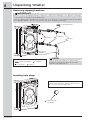
Unpacking Washer
Removing shipping hardware
Installing hole plugs
5 SPACERS
5 SPACERS
5 P CLAMPS
5 P CLAMPS
7 HOLE PLUGS
(IN BAG)
1 SHIPPING FORK
1 SHIPPING FORK
Remove all of the following:
Locate 7 hole plugs in the small bag supplied
with washer instruction guides. Insert them in
the holes in washer back panel.
UNIVERSAL
WRENCH
(IF INCLUDED)
5 BOLTS
5 BOLTS
NOTE
Rubber expansion material on spacers may
need time to relax before they can be easily
pulled through shipping hole.
IMPORTANT
Failure to remove shipping hardware completely could result in damage to the appliance, damage
to your home, or unexpected washing results.
Save all shipping bolts and spacers for future use. If the washer is to be transported at a later date,
the shipping hardware must be reinstalled to help prevent shipping damage.

9
RUBBER WASHERS
MUST BE PRESENT
USE ONLY
NEW HOSES
Leveling your washer
Excessive noise and vibration can be prevented by
properly leveling the washer.
1. For free standing installation and with the
washer within 4 feet (1 m) of its fi nal location,
place a level on top of the washer.
2. Use the universal wrench to adjust the leveling
legs so the washer is level front-to-rear and
side-to-side, and stable corner-to-corner.
3. Press down on alternate corners and sides
and feel for the slightest movement. Adjust the
appropriate leg(s) so the washer sits solidly on
the fl oor on ALL four legs. Keep the leveling leg
extension at a minimum for best performance
of the washer.
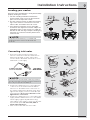
Connecting inlet water
1. Run some water from the hot and cold
faucets to fl ush the water lines and remove
particles that might clog the water valve
screens and to determine which faucet is hot
and which is cold supply.
2. Connect the HOT inlet hose to the HOT inlet
connection on the washer and the COLD
inlet hose to the COLD inlet connection on
the washer. Tighten by hand until snug. Then
tighten each supply connection another 2/3
turn with pliers. Do not cross thread or over-
tighten these connections.
3. Connect the HOT inlet hose to the HOT water
supply and the COLD inlet hose to the COLD
water supply. Tighten by hand until snug.
Then tighten each supply connection another
2/3 turn with pliers. Do not bend, kink or
pinch water inlet hoses.
4. Turn on the water and check for leaks.
raise
lower
a
b
cd
a
e
f
g
b
c
d
COLD
HOT
Installation Instructions
NOTE
For pedestal installations, see additional
installation instructions included with the
pedestal.
NOTE
Hoses are not included with washer purchase.
See “Accessories” section for various inlet hose
kits to fi t your specifi c installation.

10
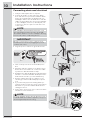
CABLE TIE
ANTI-SIPHON
DISC
1. Verify the anti-siphon disc is in place.
2. Form a “U” shape on the end of the drain
hose with the hose pointed toward the drain.
Place the formed end in a laundry tub or a
standpipe and secure the drain hose with the
cable tie (provided in the enclosure package)
to the standpipe, inlet hose, laundry tub, etc.
so the hose does not pull out from the force
of the water.
Connecting drain and electrical
3. Plug the power cord into a grounded outlet.
4. Turn on the power at a circuit breaker/fuse
box.
5. Carefully slide the washer to its fi nal position.
Recheck for level and rock corners for stabil-
ity. Remove and discard door tape.
6. Read the Use & Care Guide provided with the
washer. It contains valuable and helpful infor-
mation that will save you time and money.
7. Run the washer through a complete cycle,
checking for water leaks and proper opera-
tion.
8. If you have any questions during initial op-
eration, please review the “Service Prevention
Checklist” in your Use & Care Guide before
calling for service.
9. Place these instructions in a location near the
washer for future reference.
Installation Instructions
NOTE
A wiring diagram and technical data sheet are
located under the washer top panel, on top of
the detergent dispenser housing.
NOTE
The standpipe inside diameter must be 1-1/4”
(3.2 cm) minimum. There must be an air gap
around the drain hose in the standpipe. A snug
hose fi t can cause a siphoning action.
IMPORTANT
Check to ensure the power is off at a circuit
breaker/fuse box before plugging the power
cord into an outlet.
type
type
Grounding
Grounding
receptacle
receptacle
wa
wa
ll
ll
Po
Po
wer cord
wer cord
with 3-prong
with 3-prong
gr
gr
ounded plug
ounded plug
Do not, under any circumstances,
Do not, under any circumstances,
cut, remove, or bypass the
cut, remove, or bypass the
grounding prong.
grounding prong.

11
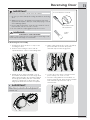
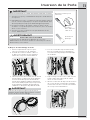
Reversing Door
IMPORTANT
Take care not to pull the door away from the
washer until you remove the wiring harness
terminal cap.
A) Removing Door Assembly
1. Completely open the door to expose all
four hinge screws.
2. Remove all four hinge screws with #2
square bit driver. Save for reinstalling later.
3. Grasp the door with both hands -one at
the handle area and one at the hinge area.
While supporting the door with the hand at
the hinge, press fi rmly with the other hand
until the locating pins on the back of the
hinge plate dislocate from the front panel.
4. While supporting the door with one hand,
pinch the tabs to release the plastic
terminal cap from the hinge plate.
x 4
5. Set the door face down on a fl at surface
protected by soft cloth or towel.
6. Release wiring harness from retainer on
plastic terminal cap. Then release terminal
from terminal cap. Save the cap to
reinstall later.
WARNING
ELECTRICAL SHOCK HAZARD
Failure to disconnect power source before servicing could
result in personal injury or even death.
IMPORTANT
BEFORE YOU REVERSE YOUR WASHER DOOR:
1. Be sure you have adequate swing area before reversing
door.
2. Gather your tools - including a screw driver with a #2
square bit and plastic knife (or small, fl at prying tool that
won’t damage paint).
3. Protect fl at work surface, such as top of washer or fl oor
near washer, with a soft cloth or towel.
4. Be sure washer is unplugged from power source!
Screwdriver with
#2 square bit
Tools needed for reversal:
Plastic
knife

12
Reversing Door
1
2
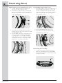
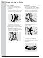
C) Reinstalling Lock and Hole Cover
1. Move the plastic cover to the other side of
the front panel. Position the cover so the
“hook” is at the bottom. Insert hook into
lower slot, slide the cover down, and press
upper retention tabs into opening until
they snap into place.
1
2
2. Insert wiring harness into door lock.
3. Insert door lock into front panel and
reinstall door lock screws.
D) Reversing Door Assembly
1. Locate nine screws on inner door ring.
Remove each and save for reinstallation
later. Remove inner door (with hinge) and
carefully set aside.
x 9
B) Removing Door Lock and Plastic Hole Cover
1. Locate and remove both screws from
door lock. Save screws for later.
2. Rotate the lock as you pull it out through
the front panel. Take care not to pull too
hard or too far as the lock is still attached
to the wiring harness.
1
2
3. Disconnect the wiring harness terminal
from the door lock. Set the door lock aside
for reinstallation later.
4. Pry upward the bottom of the plastic hole
cover to release it from the front panel.
You may have to use a nan-scratching
plastic knife if you are unable to release
it manually. Slide the cover down slightly
and remove it from the front panel.

13
Reversing Door
x 4
180
180
x 9
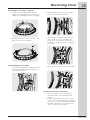
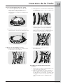
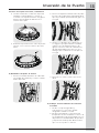
Reversing Door Assembly, continued
2. Lift door glass slightly and rotate 180
degrees, setting it back onto outer door.
Make sure the alignment tabs reengage.
3. Reinstall inner door onto outer door with
nine screws removed earlier.
E) Reinstalling Door Assembly
1. Insert the wiring harness terminal into the
terminal cap and wrap the harness into
the harness retainer.
E) Verify Reversed Door Operation
1. Test door for free, smooth swinging
operation and secure latching when
closed.
2. Plug in washer and close the door. Test
correct door lock operation by starting a
test cycle: lock should engage, and door
should not be able to be opened until
cycle is paused or canceled.
2. Slide terminal cap onto back of hinge
plate until tabs snap into place.
3. Insert hinge locating pins into the hole
that were previously covered by the
plastic hole cover. Press on the face of
the hinge to snap the other locating pins
into place.
4. Reinstall all four screws removed earlier.

14
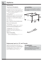
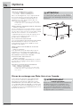
Options
Accessories
MATCHING STORAGE PEDESTAL*
White Pedestal - P/N EPWD157SIW
Titanium Pedestal - P/N EPWD157STT
A storage pedestal accessory, specifi cally
designed for this washer may be used to elevate
the washer for ease of use. This pedestal will
add about 15” (38 cm) to the height of your unit.
*Other colors may be available. Contact the source
where you purchased your washer.
DRYER STACKING KIT
P/N STACKIT7X
Depending on the model you purchased, a kit for
stacking a matching dryer on top of this washer
may have been included in the initial purchase
of your dryer. If your model did not include a
stacking kit or you desire another stacking kit, you
may order one.
INLET HOSE KITS
Please call 866-233-8353 (in Canada, 800-265-
8352) to explore hose kit options that will meet
your specifi c installation needs.
DRAIN HOSE EXTENSION KIT
P/N 137098000
In order to reach standpipe heights or distances
beyond the reach of the drain hose supplied,
order the DRAIN HOSE EXTENSION KIT.
UNIVERSAL APPLIANCE WRENCH
P/N 137019200
A UNIVERSAL APPLIANCE WRENCH is
available to aid in dryer/washer/pedestal feet
adjustment.
TOUCH UP PAINT PENS*
White - P/N 5304468812
Titanium - P/N 5304475700
*Other colors may be available. Contact the source
where you purchased your washer.
26.5”
26.5”
(67 cm)
(67 cm)
15”
15”
(38 cm)
(38 cm)
27”
27”
(68.5 cm)
(68.5 cm)
Replacement parts in U.S. and Canada:
If replacements parts are needed for your
washer, you can contact the source where you
purchased your washer, call 1-877-4ELECTROLUX
(1-877-435-3287) in the U.S. or 1-800-265-8352
in Canada, or visit our website, www.
electroluxappliances.com, for the Electrolux
Authorized Parts Distributor nearest you.
CAUTION
Failure to use accessories manufactured by (or
approved by) the manufacturer could result in
personal injury, property damage or damage
to the washer.
WARNING
ELECTRICAL HAZARD
Label all wires prior to disconnection when
servicing controls. Wiring errors can cause
improper and dangerous operation. Verify
proper operation after servicing.

EN FRONT LOAD WASHER
FR LAVEUSE Á CHARGEMENT FRONTAL
ES LAVADORA DE CARGA FRONTAL
INSTALLATION INSTRUCTIONS
INSTRUCTIONS D’INSTALLATION
INSTRUCCIONES DE INSTALACIÓN

2
Mesures de Sécurité Importantes
©2015 Electrolux Major Appliances Tous droits réservés.
• Détruisez le carton d’emballage et les sacs en plastique après avoir déballé l’appareil. Les enfants
pourraient les utiliser pour jouer. Le carton recouvert de tapis, les couvertures et les feuilles de plas-
tique peuvent être étanches à l’air et provoquer la suff ocation. Déposez tous les matériaux d’embal-
lage dans un conteneur à déchets ou faites en sorte que les enfants ne puissent y avoir accès.
• Pour votre sécurité, l’information contenue dans ces instructions doit être suivie afi n de réduire
les risques d’incendie ou d’explosion ou pour prévenir les dommages matériels, les blessures ou
la mort. Vous ne devez ni entreposer, ni utiliser d’essence ou d’autres vapeurs ou liquides infl am-
mables à proximité de cet appareil ou de tout autre appareil électroménager.
• Installez l’appareil conformément aux instructions du fabricant et aux codes locaux.
• L’installation électrique de la laveuse doit être conforme aux codes et aux règlements locaux ainsi
qu’à la toute dernière édition du National Electrical Code (ANSI/NFPA 70), ou au Canada, au
Code canadien de l’électricité (C22.1, article 1).
• Pour éviter les blessures au dos ou d’autres types de blessure, demandez l’aide d’autres personnes
pour déplacer ou soulever la laveuse.
• Ne superposez pas une sécheuse sur une laveuse déjà installée sur un socle. Ne superposez pas
une laveuse sur une sécheuse. Ne superposez pas une laveuse sur une autre laveuse.
• Les instructions comprises dans ce guide et toute autre documentation fournie avec cet appareil
ne sont pas conçues pour couvrir toutes les éventualités ou situations qui pourraient survenir. Vous
DEVEZ faire preuve de bon sens et de prudence durant l’installation, l’utilisation et l’entretien de
tout appareil ménager.
Conservez ces instructions pour vous y reporter ultérieurement.
Table des matières
Mesures de Sécurité Importantes .............................2
Exigences d’Installation ........................................... 3-6
Déballage de la Laveuse.........................................7-8
Instructions d’Installation........................................9-10
Inversion de la Porte ................................................11-14
Options .............................................................................. 15
AVERTISSEMENT
RISQUE D’INCENDIE - Lisez toutes les instructions de sécurité suivantes avant d’installer et
d’utiliser votre appareil :
Ce symbole vous avertit à propos des situations
pouvant causer des dommages matériels ou
des blessures.
Ce symbole vous avertit à propos des situations
pouvant causer des dommages matériels, des
blessures graves ou même la mort.
AVERTISSEMENT
ATTENTION
Sachez reconnaître les symboles, les
avertissements et les étiquettes de
sécurité.
Les mesures de sécurité présentées dans ce guide
sont identifi ées par le mot AVERTISSEMENT ou
ATTENTION selon le type de risque présenté.
AVERTISSEMENT
Pour votre sécurité, l’information contenue dans ces instructions doit être suivie afi n de réduire
les risques d’incendie ou d’explosion ou pour prévenir les dommages matériels, les blessures
ou la mort. Vous ne devez ni entreposer, ni utiliser d’essence ou d’autres vapeurs ou liquides
infl ammables à proximité de cet appareil ou de tout autre appareil électroménager.

3
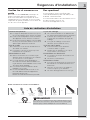
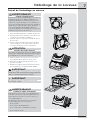
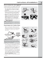
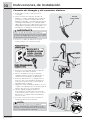
REMARQUE
Les tuyaux ne sont pas inclus avec l’achat laveuse. Voir
la section « Accessoires » pour divers trousse de tuyaux
d’entrée qui pourrait s’adapter à votre installation.
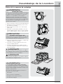
Exigences d’Installation
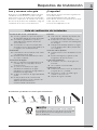
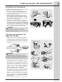
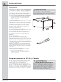
Outils et matériel nécessaires à l’installation :
Liste de vérifi cation d’installation
Tuyau de vidange
La colonne montante ou le drain de mur
est à une hauteur d’au moins 61 cm (24 po)
S’assurer que le disque anti-siphon
est bien fi xé à l’extrémité du tuyau de
vidange
Le tuyau de vidange est fi xé avec
l’attache (incluse dans la cuve)
Inversion de la porte
Suivez les instructions détaillées
contenues dans ce guide
Vérifi ez que la charnière et le loquet
fonctionnent correctement
Alimentation en électricité
Le système électrique de la maison est
sous tension
La laveuse est branchée
Vérifi cations fi nales
Vous avez lu entièrement les instructions
d’installation et le Guide d’utilisation et
d’entretien
La porte se verrouille et le tambour
tourne lorsqu’un cycle démarre
La carte d’enregistrement est envoyée
Matériel d’expédition
Le support d’expédition en mousse (sous
la cuve de lavage) a été enlevé et remisé
Les boulons d’expédition situés à l’arrière
de l’appareil ont été enlevés et remisés
Les bouchons (inclus dans le sac situé dans
la cuve) ont été insérés dans les trous situés
dans la paroi arrière de la laveuse
Mise à niveau
La laveuse est au niveau latéralement et
de l’avant vers l’arrière
Les quatre coins de la caisse reposent
fermement sur le plancher
Alimentation en eau
Utilisez seulement les nouveaux tuyau
d’entrée d’eau et vérifi er que les rondelles
en caoutchouc sont en place.
Le tuyau d’entrée d’eau CHAUDE est
raccordé au robinet d’eau CHAUDE et le
tuyau d’entrée d’eau FROIDE est raccordé
au robinet d’eau FROIDE
Les robinets d’eau CHAUDE et d’eau
FROIDE sont ouverts
Les raccords d’alimentation en eau ou les
raccords d’arrivée d’eau de l’appareil ne
présentent aucune fuite -
refaites une vérifi cation 24 heures plus tard
Veuillez lire et conserver ce
guide
Merci d’avoir choisi Electrolux, la marque de
qualité en matière d’électroménager. Ces
instructions d’installation font partie de notre
engagement à vous satisfaire et à vous fournir
un produit de qualité pendant toute la durée de
vie de votre nouvel appareil.
Des questions?
Pour rejoindre le service aux États-Unis :
1-877-4ELECTROLUX (1-877-435-3287) et au
Canada : 1-800-265-8352.
Pour obtenir de l’aide et de l’information sur les
produits en ligne, visitez le site
www.electroluxappliances.com.
OU OU OU ET ET
Pince
réglable
Clé à
molette
Clé polygonale
de 3/8 po
ou de 10 mm
Cliquet et
ensemble
de douilles
Niveau de charpentier
Clé universelle
optionnel
Tuyaux d’alimentation (x2)

4
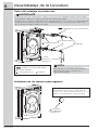
Exigences d’Installation
Exigences des systèmes élec-
triques
Exigences relatives à l’alimen-
tation en eau
Exigences relatives à la mise
à la terre
Exigences relatives au sys-
tème d’évacuation
CIRCUIT - Circuit indépendant de 15 ampères,
polarisé et mis à la terre, avec fusible
temporisé ou disjoncteur de 15 A.
ALIMENTATION ÉLECTRIQUE - Câble
monophasé à deux fi ls mis à la terre,
120 volts, 60 Hz; courant alternatif.
PRISE - Prise à trois alvéoles et mise à la terre
située à un endroit où il est possible de
raccorder le cordon d’alimentation de la laveuse
une fois que cette dernière est installée.
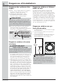
1. Cet appareil DOIT être mis à la terre. En cas
de mauvais fonctionnement ou de panne, la
mise à la terre diminue les risques de choc
électrique en fournissant au courant élec-
trique une trajectoire de moindre résistance.
2. Étant donné que votre laveuse est équipée d’un
cordon d’alimentation pourvu d’un conducteur de
mise à la terre et d’une fi che de mise à la terre, la
fi che DOIT être raccordée à une prise appropriée
(avec conducteurs en cuivre) correctement ins-
tallée et mise à la terre conformément aux codes
et règlements locaux ou, si aucun code local ne
régit ce type d’installation, à la plus récente édi-
tion du National Electrical Code (ANSI/NFPA 70).
En cas de doute, faites appel à un électricien
qualifi é. NE COUPEZ PAS et NE MODIFIEZ PAS
la broche de mise à la terre du cordon d’alimen-
tation. Si votre prise murale n’est pourvue que de
deux fentes, il incombe au propriétaire de faire
appel à un électricien qualifi é pour la remplacer
par une prise à trois alvéoles et mise à la terre de
façon adéquate.
Les robinets d’eau chaude et d’eau froide
DOIVENT être installés à une distance de
longueur de tuyau ou moins de l’arrivée d’eau
de votre laveuse. Les robinets DOIVENT être de
1,9 cm (3/4 po) et fi letés en fonction d’un rac-
cordement de tuyau de laveuse. La pression de
l’eau DOIT se situer entre 206,8 et 827,4 kPa (30
et 120 lb/po²). La diff érence de pression entre
l’eau chaude et l’eau froide ne doit pas dépas-
ser 68,9 kPa (10 lb/po²). Le service des eaux de
votre localité peut vous informer sur la pression
de votre alimentation en eau.
1. Le drain doit pouvoir évacuer 64,3 L (17 gal)
d’eau à la minute.
2. Tuyau d’évacuation d’au moins 3,18 cm (1-
1/4 po) de diamètre.
3. Le tuyau d’évacuation doit être situé entre une
hauteur minimale de 61 cm (24 po) et une
hauteur maximale de 244 cm (96 po)
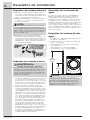
REMARQUE
Étant donné les variations de tension possibles,
l’utilisation de cette laveuse avec une source
d’alimentation produite par une génératrice à
essence, solaire ou éolienne ou par toute autre
source d’alimentation diff érente de celle fournie
par les services publics n’est pas recommandée.
REMARQUE
Le tuyau de vidange raccordé à la laveuse
peut convenir à un tuyau d’évacuation de
188 cm (74 po) de hauteur. Pour des tuyaux
d’évacuation plus hauts, utilisez le tuyau
portant le numéro de pièce 137098000 que
vous pouvez obtenir auprès d’un distributeur
de pièces autorisé.
AVERTISSEMENT
RISQUE DE CHOC ÉLECTRIQUE
Un raccordement inadéquat du conducteur de
terre de l’équipement peut accroître les risques
de choc électrique. En cas de doute quant à
la mise à la terre de l’appareil, consultez un
électricien qualifi é.
Prise murale
Prise murale
avec mise
avec mise
à la terre
à la terre
Ne coupez pas, n'enlevez pas et
Ne coupez pas, n'enlevez pas et
ne mettez pas hors circuit la broche
ne mettez pas hors circuit la broche
de mise à la terre de cette che.
de mise à la terre de cette che.
Cordon électrique muni
Cordon électrique muni
avec mise à la terre
avec mise à la terre
d’une che à trois broches
d’une che à trois broches
96”
(244
cm)
max.
24”
(61
cm)
min.

5
Exigences d’Installation
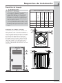
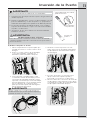
Exigences de dégagement
1”
(2.5
cm)
0”
(0
cm)
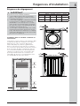
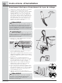
Installation dans un Endroit en Retrait ou
une Armoire
Si la laveuse et la sécheuse sont installées dans
le même placard, une ventilation est requise
dans la porte : Une ouverture d’au moins
774,2 cm2 (120 po2), divisée également au-
dessus et au-dessous de la porte, est requise.
Les ouvertures à persiennes doivent être situées
à 7,6 cm (3 po) du haut et du bas de la porte.
Les ouvertures d’aération ne doivent pas être
obstruées lorsqu’une porte est installée. Une
porte à persiennes dont les ouvertures sur
l’ensemble de la porte sont équivalentes aux
recommandations peut être utilisée.
60 sq. in.
(387.1cm²)
3”
(7.6cm)
60 sq. in.
(387.1cm²)
3”
(7.6cm)
porte de placard
IMPORTANT
N’INSTALLEZ PAS VOTRE LAVEUSE :
1. ...à un endroit exposé aux écoulements
d’eau ou aux aléas des conditions météo-
rologiques extérieures.
2. ...à un endroit (garage ou bâtiment similaire)
où de l’essence ou d’autres substances
infl ammables sont entreposées. Si la ma-
chine à laver est installée dans un garage,
elle doit être élevée à un minimum de 45,7
cm (18 po) au-dessus du sol.
3. ...sur un tapis. Le plancher DOIT être solide
et présenter une pente inférieure à 2,5 cm
(1 po). Afi n d’éviter les vibrations et le dépla-
cement de l’appareil, il peut être nécessaire
de renforcer le plancher.
DÉGAGEMENTS MINIMAUX - Centimètres (pouces)
CÔTÉS ARRIÈRE DESSUS AVANT
Alcôve 0 cm (0”) 0 cm (0”) 0 cm (0”) n/a
Sous le
comptoir
0 cm (0”) 0 cm (0”) 0 cm (0”) n/a
Placard 0 cm (0”) 0 cm (0”) 0 cm (0”) 2.5 cm (1”)
0”
(0
cm)
0”
(0
cm)

6
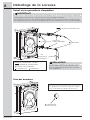
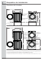
Exigences d’Installation
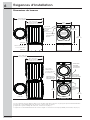
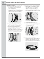
Dimensions de laveuse
*Le raccordement du tuyau d’arrivée d’eau sur les modèles à la vapeur ajoute 2 cm (3/4 po) à la profondeur d’installation.
1
Longueur du cordon d’alimentation de la laveuse, environ 152,5 cm (60 po).
2
Longueur du tuyau de vidange de la laveuse, environ 150 cm (59 po).
3
Longueur du cordon d’alimentation de la sécheuse à gaz ou la sécheuse électrique (Canada), environ 152,5 cm (60 po).
raccord de
l’alimentation
en eau à
l’arrière
de la laveuse
alimentation
électrique
à l’arrière de
la sécheuse
3
alimentation en
gaz à l’arrière de
l’appareil à gaz
hauteur de la
ligne centrale
de l’évent arrière
53.5” (136 cm)*
avec la porte grande ouverte
53.5” (136 cm)*
avec la porte grande ouverte
31.5” (79.5 cm)*
à partir de l’avant de la
porte lorsqu’elle est fermée
31.5” (79.5 cm)*
à partir de l’avant de la
porte lorsqu’elle est fermée
41.0”
(105 cm)
39.0”
(99 cm)
27.0”
(68.5 cm)
raccord de
l’alimentation
en eau à l’arrière
de la laveuse
Tuyau de
vidange
à l’arrière de
la laveuse
2
tuyau de vidange
à l’arrière de la
laveuse
3
cordon
d’alimentation
à l’arrière de la
laveuse
1
cordon
d’alimentation
à l’arrière de
la laveuse
1
plancher
plancher
plancher
laveuse autonome
sur le plancher
laveuse montée sur
le socle optionnel
38.0”
(96.5 cm)
53.25”
(135.5 cm)
La page est en cours de chargement...
La page est en cours de chargement...
La page est en cours de chargement...
La page est en cours de chargement...
La page est en cours de chargement...
La page est en cours de chargement...
La page est en cours de chargement...
La page est en cours de chargement...
La page est en cours de chargement...
La page est en cours de chargement...
La page est en cours de chargement...
La page est en cours de chargement...
La page est en cours de chargement...
La page est en cours de chargement...
La page est en cours de chargement...
La page est en cours de chargement...
La page est en cours de chargement...
La page est en cours de chargement...
La page est en cours de chargement...
La page est en cours de chargement...
La page est en cours de chargement...
La page est en cours de chargement...
La page est en cours de chargement...
La page est en cours de chargement...
-
 1
1
-
 2
2
-
 3
3
-
 4
4
-
 5
5
-
 6
6
-
 7
7
-
 8
8
-
 9
9
-
 10
10
-
 11
11
-
 12
12
-
 13
13
-
 14
14
-
 15
15
-
 16
16
-
 17
17
-
 18
18
-
 19
19
-
 20
20
-
 21
21
-
 22
22
-
 23
23
-
 24
24
-
 25
25
-
 26
26
-
 27
27
-
 28
28
-
 29
29
-
 30
30
-
 31
31
-
 32
32
-
 33
33
-
 34
34
-
 35
35
-
 36
36
-
 37
37
-
 38
38
-
 39
39
-
 40
40
-
 41
41
-
 42
42
-
 43
43
-
 44
44


Electrolux EFLS517SIW Guide d'installation
- Catégorie
- Sèche-linge électriques
- Taper
- Guide d'installation