
NOTE: THIS INSTRUCTION
BOOKLET CONTAINS IMPORTANT
SAFETY INFORMATION.
PLEASE READ AND KEEP FOR
FUTURE REFERENCE.
English pg 1-24
Français pg 25-28
Español pg 29-32
Lot # 386785 12/14/15
Purchased: __________________
Be sure to give us a ring before
making any returns. 1-800-523-3987
Computer Desk
Harbor View Collection | Model 401685
Need help? Visit Sauder.com to view video assembly tips or chat with a live rep.
Prefer the phone? Call 1-800-523-3987.
Share your journey!
sauder.com
Sit and surf.

Table of Contents Assembly Tools Required
2-3
4-5
6-24
25-28
29-32
33-34
35
Part Identifi cation
Hardware Identifi cation
Assembly Steps
Français
Español
Safety
Warranty
Hammer
Not actual size
No. 2 Phillips Screwdriver
Tip Shown Actual Size
Skip the power trip.
This time.
401685 www.sauder.com/servicesPage 2
Part Identifi cation
å While not all parts are labeled, some of the parts will have a label or an inked letter on the edge
to help distinguish similar parts from each other. Use this part identifi cation to help identify similar parts.
A2 RIGHT END (1)
B2 LEFT END (1)
C3 UPRIGHT (1)
D TOP (1)
D28 RIGHT DRAWER SIDE (1)
D29 LEFT DRAWER SIDE (1)
D30 RIGHT SMALL DRAWER SIDE (1)
D31 LEFT SMALL DRAWER SIDE (1)
D77 SMALL DRAWER BACK (1)
D78 DRAWER BACK (1)
D707 DRAWER BOTTOM (1)
D716 SMALL DRAWER BOTTOM (1)
E BOTTOM (1)
F SHELF (1)
G MODESTY PANEL (1)
H BACK (1)
I SMALL DRAWER FRONT (1)
M DRAWER FRONT (1)
R KEYBOARD SHELF (1)
SS KEYBOARD FRONT (1)
T KEYBOARD BACK (1)
U KEYBOARD SIDE (2)
V FRONT MOLDING (1)
W MOLDING (1)
X BASE (1)

Part Identifi cation
Now you know
our ABCs.
401685www.sauder.com/services
Page 3
A2
B2
C3
D
E
F
G
H
V
W
X
D716
D30
D31
D77
I
R
SS
T
U
U
D707
D28
D29
D78
M

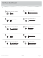
Hardware Identifi cation
å Screws are shown actual size. You may receive extra hardware with your unit.
401685 www.sauder.com/servicesPage 4
35GA
CABINET RIGHT - 1
35GB
CABINET LEFT - 1
35GC
DRAWER RIGHT - 1
35GD
DRAWER LEFT - 1
40CA
CABINET RIGHT - 1
40CB
CABINET LEFT - 1
40CC
DRAWER RIGHT - 1
40CD
DRAWER LEFT - 1
ANGLE
BRACKET - 5
27G
RAIL BRACKET - 2
33G
10A
SLIDE CAM - 4
METAL PIN - 3
1R87K
KNOB - 3
FILE GLIDE - 2
15B
29M
BUMPER
CARD - 1
HINGE - 2
12H
40AW
CABINET RIGHT - 1
40AX
CABINET LEFT - 1
40AY
DRAWER RIGHT - 1
40AZ
DRAWER LEFT - 1
HIDDEN CAM - 13
1F
CAM DOWEL - 13
2F
NAIL - 18
5N

Hardware Identifi cation
å Screws are shown actual size. You may receive extra hardware with your unit.
401685www.sauder.com/services
Page 5
BLACK 1-7/8" FLAT HEAD SCREW - 4
2S
BROWN 1-1/2" FLAT HEAD SCREW - 6
14S
BLACK 1-1/4" FLAT HEAD SCREW - 4
7S
SILVER 1-1/4" PAN HEAD SCREW - 2
45S
18S
BROWN 1" FLAT HEAD SCREW - 4
SILVER 5/8" FLAT HEAD SCREW - 4
23S
30S
BLACK 1-9/16" FLAT HEAD SCREW - 8
BLACK 9/16" LARGE HEAD SCREW - 16
1S
GOLD 5/16" FLAT HEAD SCREW - 20
3S
BLACK 1-1/2” PAN HEAD SCREW - 1
49S

Step 1
Look for this icon. It means a
video assembly tip is available at
www.sauder.com/services/tips
å
Assemble your unit on a carpeted fl oor or on the empty
carton to avoid scratching your unit or the fl oor.
å
Push thirteen HIDDEN CAMS (1F) into the ENDS (A2
and B2), UPRIGHT (C3), BOTTOM (E), SHELF (F), and
MODESTY PANEL (G). Then, insert a CAM DOWEL (2F)
into each HIDDEN CAM.
401685 www.sauder.com/servicesPage 6
Do not tighten the HIDDEN CAMS in this step.
(13 used)
Arrow
A2
B2
C3
E
F
G
Insert the metal end of the CAM
DOWEL into the HIDDEN CAM.
Arrow
1F
2F
Scan this QR code or go to this address:
http://qr.sauder.com/?ID=1598
to watch a video on how to assemble your unit.

å
Fasten the CABINET RIGHTS (35GA and 40CA) to the
UPRIGHT (C3) and the CABINET LEFTS (35GB and 40CB)
to the LEFT END (B2). Use eight GOLD 5/16" FLAT HEAD
SCREWS (3S) through holes #1 and #3.
Step 2
401685www.sauder.com/services
Page 7
B2
C3
1
2
3
1
2
3
1
2
3
4
1
2
3
4
Roller end
Roller end
Surface with
HIDDEN CAMS
Edge with
CAM DOWELS
Edge with
CAM DOWELS
Surface with
HIDDEN CAMS
Remember:
Righty tighty.
Lefty loosey.
GOLD 5/16" FLAT HEAD SCREW
(8 used in this step)
3S

Step 3
å
Fasten the RAIL BRACKETS (33G) to the RIGHT END (A2).
Use four BLACK 9/16" LARGE HEAD SCREWS (1S).
å
Fasten the CABINET LEFT (40AX) to the UPRIGHT (C3).
Use two GOLD 5/16" FLAT HEAD SCREWS (3S).
å
NOTE: The CABINET RIGHT will be attached in step 8.
401685 www.sauder.com/servicesPage 8
A2
C3
33G
Surface without
HIDDEN CAMS
Surface with
HIDDEN CAMS
Roller end
Roller end
GOLD 5/16" FLAT HEAD SCREW
(2 used for the RAIL)
3S
40AX
40AX
Notched edge
BLACK 9/16" LARGE HEAD SCREW
(4 used for the RAIL BRACKETS)
1S

å
Fasten the LEFT END (B2) and UPRIGHT (C3) to the
BOTTOM (E). Tighten four HIDDEN CAMS.
Step 4
401685www.sauder.com/services
Page 9
Start Tighten
Arrow
Minimum
190 degrees
Caution
Risk of damage or
injury. HIDDEN CAMS
must be completely
tightened. HIDDEN
CAMS that are not
completely tightened
may loosen, and parts
may separate. To
completely tighten:
Arrow
Maximum
210 degrees
C3
B2
E
Surface with
HIDDEN CAMS
Surface without
HIDDEN CAMS
These holes must be here.
Surface
with
HIDDEN
CAMS
Do not stand the unit upright without the
BACK fastened. The unit may collapse.
Caution

Step 5
å
Insert three METAL PINS (1R) into the MODESTY PANEL (G).
å
Fasten the MODESTY PANEL (G) to the UPRIGHT (C3). Use
two BLACK 1-7/8" FLAT HEAD SCREWS (2S).
401685 www.sauder.com/servicesPage 10
C3
1R
G
Surface with
HIDDEN CAMS
BLACK 1-7/8" FLAT HEAD SCREW
(2 used in this step)
2S
Curved edge

å
Push the SHELF (F) onto the METAL PINS in the
MODESTY PANEL (G).
å
Fasten the SHELF (F) to the UPRIGHT (C3). Use two
BLACK 1-7/8" FLAT HEAD SCREWS (2S).
å
Fasten the RIGHT END (A2) to the SHELF (F) and
MODESTY PANEL (G). Tighten three HIDDEN CAMS.
Step 6
401685www.sauder.com/services
Page 11
Arrow
Minimum
190 degrees
Maximum
210 degrees
G
F
BLACK 1-7/8" FLAT HEAD SCREW
(2 used in this step)
2S
C3
A2
Surface without
HIDDEN CAMS
Surface with
HIDDEN CAM
Notched edge
Finished edge

Step 7
å
Fasten the FRONT MOLDING (V) to the TOP (D). Use four
BLACK 1-1/4" FLAT HEAD SCREWS (7S).
å
NOTE: Do not overtighten the SCREWS.
401685 www.sauder.com/servicesPage 12
Flat edge
Rounded edge
Surface
with holes
V
D
BLACK 1-1/4" FLAT HEAD SCREW
(4 used in this step)
7S

å
Fasten the CABINET RIGHT (40AW) to the RAIL
BRACKETS on the RIGHT END (A2). Use two GOLD
5/16" FLAT HEAD SCREWS (3S).
å
Fasten the TOP (D) to the ENDS (A2 and B2) and
UPRIGHT (C3). Tighten six HIDDEN CAMS.
Step 8
401685www.sauder.com/services
Page 13
B2
A2
C3
Roller end
D
V
Surface
with holes
Arrow
Minimum
190 degrees
Maximum
210 degrees
GOLD 5/16" FLAT HEAD SCREW
(2 used for the RAIL)
3S
40AW
40AW

Step 9
401685 www.sauder.com/servicesPage 14
å
Slide the MOLDING (W) onto the notched edge of the
RIGHT END (A2).
å
*U.S. Patent No. 5,499,886
Notched edge
Slide the MOLDING (W)
onto the notched edge.
A2
W

å
Fasten four ANGLE BRACKETS (27G) to the LEFT END (B2),
UPRIGHT (C3), and BOTTOM (E). Use four BLACK 9/16"
LARGE HEAD SCREWS (1S).
å
NOTE: Be sure the ANGLE BRACKETS are even with the
edges of the END, UPRIGHT, and BOTTOM.
å
Fasten the BASE (X) to the LEFT END (B2), UPRIGHT (C3), and
BOTTOM (E). Use four BLACK 9/16" LARGE HEAD SCREWS (1S)
through the ANGLE BRACKETS and into the BASE.
Step 10
401685www.sauder.com/services
Page 15
B2
C3
E
27G
27G
27G
X
BLACK 9/16" LARGE HEAD SCREW
(8 used in this step)
Hey! It's starting to look
like something!
1S

Step 11
401685 www.sauder.com/servicesPage 16
å
Carefully turn your unit over onto its front edges. Lay the
BACK (H) over your unit.
å
Make equal margins along the top and side edges of the
BACK (H). Push on opposite corners of your unit if needed
to make it "square".
å
Fasten the BACK (H) to your unit using the NAILS (5N).
å
Fasten an ANGLE BRACKET (27G) to the RIGHT END
(A2) and MOLDING (W). Use two BLACK 9/16" LARGE
HEAD SCREWS (1S).
å
NOTE: There is no pre-drilled hole in the MOLDING. The
SCREW will tighten into the groove.
27G
A2
W
Finished surface
H
These holes must line up
over the BOTTOM (E).
Do not stand the unit upright without the
BACK fastened. The unit may collapse.
Caution
BLACK 9/16" LARGE HEAD SCREW
(2 used for the ANGLE BRACKET)
1S
NAIL
(18 used in this step)
5N

å
Fasten the KEYBOARD BACK (T) and KEYBOARD SIDES (U)
to the KEYBOARD SHELF (R). Use four BROWN 1-1/2" FLAT
HEAD SCREWS (14S).
å
Fasten the KEYBOARD BACK (T) to the KEYBOARD SIDES (U).
Use two BROWN 1-1/2" FLAT HEAD SCREWS (14S).
Step 12
401685www.sauder.com/services
Page 17
BROWN 1-1/2" FLAT HEAD SCREW
(6 used in this step)
14S
Ffi nished surface
R
U
T
U
Long fi nished edge
These surfaces should
be the same fi nish.

Step 13
401685 www.sauder.com/servicesPage 18
å
Fasten the HINGES (12H) to the KEYBOARD FRONT (SS). Use four
SILVER 5/8" FLAT HEAD SCREWS (23S)
å
Fasten the KEYBOARD HINGES (12H) to the KEYBOARD SHELF (R).
Use two BLACK 9/16" LARGE HEAD SCREWS (1S).
å
Peel a BUMPER from the BUMPER CARD (29M). Stick a BUMPER
on the KEYBOARD SIDES (U) where they come in contact with the
KEYBOARD FRONT (SS).
SILVER 5/8" FLAT HEAD SCREW
(4 used for KEYBOARD FRONT)
23S
SS
R
12H
U
U
29M
29M
BLACK 9/16" LARGE HEAD SCREW
(2 used in this step)
1S

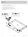
Step 14
401685www.sauder.com/services
Page 19
R
Roller end
Roller end
BROWN 1" FLAT HEAD SCREW
(4 used for the SLIDES)
18S
å
Fasten the DRAWER RIGHT (40AY) and DRAWER LEFT (40AZ)
to the KEYBOARD SHELF (R). Use four BROWN 1" FLAT HEAD
SCREWS (18S).
40AZ
40AZ
40AY
40AY

Step 15
401685 www.sauder.com/servicesPage 20
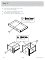
VIEW THE T-LOCK BOX VIDEO
å
Fasten the DRAWER BACK (D78) to the DRAWER SIDES (D28 and D29).
Use four BLACK 1-9/16" FLAT HEAD SCREWS (30S).
å
NOTE: Be sure the DRAWER BOTTOM (D707 ) inserts into the groove of
the DRAWER BACK (D78).
å
Repeat this step for the small drawer.
12
3
å
Insert the DRAWER SIDES (D28 and D29) at an angle
into the slot at each end of the DRAWER FRONT (M).
å
Slide the DRAWER BOTTOM (D707) into the grooves in the
DRAWER SIDES (D28 and D29) and DRAWER FRONT (M).
The tabs should insert freely
into the slots. Gently tilt the
DRAWER SIDES side to side
until the tabs slip into the slots.
Groove
Start each screw a few turns before
completely tightening any of them.
BLACK 1-9/16" FLAT HEAD SCREW
(8 used in this step)
30S
Be sure the DRAWER
BOTTOM inserts into the
DRAWER FRONT groove.
D28
D28
D28
D29
D29
D29
D707
D707
D78
M
M
Unfi nished
surface
With the palm of your
hand, tap the DRAWER
BOTTOM down into
the groove.
La page est en cours de chargement...
La page est en cours de chargement...
La page est en cours de chargement...
La page est en cours de chargement...
La page est en cours de chargement...
La page est en cours de chargement...
La page est en cours de chargement...
La page est en cours de chargement...
La page est en cours de chargement...
La page est en cours de chargement...
La page est en cours de chargement...
La page est en cours de chargement...
La page est en cours de chargement...
La page est en cours de chargement...
La page est en cours de chargement...
La page est en cours de chargement...
-
 1
1
-
 2
2
-
 3
3
-
 4
4
-
 5
5
-
 6
6
-
 7
7
-
 8
8
-
 9
9
-
 10
10
-
 11
11
-
 12
12
-
 13
13
-
 14
14
-
 15
15
-
 16
16
-
 17
17
-
 18
18
-
 19
19
-
 20
20
-
 21
21
-
 22
22
-
 23
23
-
 24
24
-
 25
25
-
 26
26
-
 27
27
-
 28
28
-
 29
29
-
 30
30
-
 31
31
-
 32
32
-
 33
33
-
 34
34
-
 35
35
-
 36
36


dans d''autres langues
Documents connexes
-
Sauder 412314 Assembly Instructions Manual
-
-
-
-
-
-
-
-
-