NEC 42XM5 PX-42XM5G Manuel utilisateur
- Catégorie
- Téléviseurs
- Taper
- Manuel utilisateur

PlasmaSync Plasma Monitor
(Enhanced split screen Model)
PlasmaSync 42XM5
PX-42XM5G
PlasmaSync 50XM6
PX-50XM6G
PlasmaSync 60XM5
PX-60XM5G
User’s Manual
Benutzerhandbuch
Manuel d’utilisation
Manual del Usuario
Manuale dell’utente
уководство пользователя
Bruksanvisning
Kullanım Kılavuzu
Εγειρίδι ρήσης
Downloaded From TV-Manual.com Manuals


En-2
Precautions
Please read this manual carefully before using your plasma monitor and
keep the manual handy for future reference.
CAUTION
RISK OF ELECTRIC SHOCK
DO NOT OPEN
CAUTION:
TO REDUCE THE RISK OF ELECTRIC SHOCK, DO
NOT REMOVE COVER. NO USER-SERVICEABLE
PARTS INSIDE.
REFER SERVICING TO QUALIFIED SERVICE
PERSONNEL.
This symbol warns the user that uninsulated voltage
within the unit may have sufficient magnitude to cause
electric shock. Therefore, it is dangerous to make any
kind of contact with any part inside of this unit.
This symbol alerts the user that important literature
concerning the operation and maintenance of this unit
has been included.
Therefore, it should be read carefully in order to avoid
any problems.
WARNING
TO PREVENT FIRE OR SHOCK HAZARDS, DO NOT EXPOSE THIS
UNIT TO RAIN OR MOISTURE. ALSO DO NOT USE THIS UNIT’S
POLARIZED PLUG WITH AN EXTENSION CORD RECEPTACLE OR
OTHER OUTLETS, UNLESS THE PRONGS CAN BE FULLY
INSERTED. REFRAIN FROM OPENING THE CABINET AS THERE
ARE HIGH-VOLTAGE COMPONENTS INSIDE. REFER SERVICING
TO QUALIFIED SERVICE PERSONNEL.
Warnings and Safety Precaution
This plasma monitor is designed and manufactured to provide
long, trouble-free service. No maintenance other than cleaning
is required. Please see the section “Plasma monitor cleaning
procedure”.
The plasma display panel consists of fine picture
elements (cells) with more than 99.99 percent active cells. There
may be some cells that do not produce light or remain lit.
For operating safety and to avoid damage to the unit, read
carefully and observe the following instructions.
To avoid shock and fire hazards:
1. Provide adequate space for ventilation to avoid internal heat build-
up. Do not cover rear vents or install the unit in a closed cabinet or
shelves.
If you install the unit in an enclosure, make sure there is adequate
space at the top of the unit to allow hot air to rise and escape. If the
monitor becomes too hot, the overheat protector will be activated and
the monitor will be turned off. If this happens, turn off the power to the
monitor and unplug the power cord. If the room where the monitor is
installed is particularly hot, move the monitor to a cooler location, and
wait for 60 minutes to cool the monitor. If the problem persists, contact
your dealer for service.
2. Do not use this unit’s polarized plug with extension cords or outlets
unless the prongs can be completely inserted.
3. Do not expose the unit to water or moisture.
4. Avoid damage to the power cord, and do not attempt to modify the
power cord.
5. Unplug the power cord during electrical storms or if the unit will
not be used over a long period.
6. Do not open the cabinet which has potentially dangerous high voltage
components inside. If the unit is damaged in this way the warranty will
be void. Moreover, there is a serious risk of electric shock.
7. Do not attempt to service or repair the unit. The manufacturer is not
liable for any bodily harm or damage caused if unqualified persons
attempt service or open the back cover. Refer all service to authorized
Service Centers.
8. This equipment shall be connected to a MAIN outlet with a protective
earth-ground connection.
9. The outlet shall be installed near the equipment and shall be easily
accessible.
Important Information
To avoid damage and prolong operating life:
1. Use only with 100 V to 240 V 50 Hz/60 Hz AC power supply. Continued
operation at line voltages greater than 100 V to 240 V AC will shorten
the life of the unit, and might even cause a fire hazard.
2. Handle the unit carefully when installing it and do not drop.
3. Set the unit away from heat, excessive dust, and direct sunlight.
4. Protect the inside of the unit from liquids and small metal objects. In
case of accident, unplug the power cord and have it serviced by an
authorized Service Center.
5. Do not hit or scratch the panel surface as this causes flaws on the surface
of the screen.
6. For correct installation and mounting it is strongly recommended to
use a trained, authorized dealer.
7. As is the case with any phosphor-based display (like a CRT monitor,
for example) light output will gradually decrease over the life of a Plasma
Display Panel.
8. To avoid sulfurization it is strongly recommended not to place the unit
in a dressing room in a public bath or hot spring bath.
9. Do not use in a moving vehicle, as the unit could drop or topple over
and cause injuries.
10. Do not place the unit on its side, upside-down or with the screen facing
up or down, to avoid combustion or electric shock.
11. To prevent a fire hazard, do not place near an open flame (such as a
lighted candle).
Plasma monitor cleaning procedure:
1. Use a soft dry cloth to clean the front panel and bezel area. Never use
solvents such as alcohol or thinner to clean these surfaces.
2. Clean plasma ventilation areas with a vacuum cleaner with a soft brush
nozzle attachment.
3. To ensure proper ventilation, cleaning of the ventilation areas must be
carried out monthly. More frequent cleaning may be necessary
depending on the environment in which the plasma monitor is installed.
Recommendations to avoid or minimize image retention:
Like all phosphor-based display devices and all other gas plasma displays,
plasma monitors can be susceptible to image retention under certain
circumstances. Certain operating conditions, such as the continuous
display of a static image over a prolonged period of time, can result in
image retention if proper precautions are not taken. To protect your
investment in this plasma monitor, please adhere to the following
guidelines and recommendations for minimizing the occurrence of image
retention:
* Always enable and use your computer’s screen saver function
during use with a computer input source.
* Display a moving image whenever possible.
* Change the position of the menu display from time to time.
* Always power down the monitor when you are finished using it.
If the plasma monitor is in long term use or continuous operation take the
following measures to reduce the likelihood of image retention:
* Lower the Brightness and Contrast levels as much as possible without
impairing image readability.
* Display an image with many colors and color gradations (i.e.
photographic or photo-realistic images).
* Create image content with minimal contrast between light and dark
areas, for example white characters on black backgrounds. Use
complementary or pastel color whenever possible.
* Avoid displaying images with few colors and distinct, sharply defined
borders between colors.
Plasma monitor driving sound
The panel of the Plasma monitor is composed of extremely fine pixels and
these pixels emit light according to received video signals. This principle
may cause you to hear a buzz or electrical hum coming from the Plasma
monitor. Also note that the rotation speed of the cooling fan motor increases
when the ambient temperature of the Plasma monitor becomes high. You
may hear the sound of the motor at that time.
Note:
The following items are not coverd by the warranty.
• Image retention
• Panel generated sound, examples: Fan motor noise, and electrical
circuit humming /glass panel buzzing.
Contact your dealer for other recommended procedures that will best
suit your particular application needs.
Downloaded From TV-Manual.com Manuals

En-3
CAUTION
When disposing of used batteries, please comply with
governmental regulations or environmental public
instruction’s rules that apply in your country/area.
Disposing of your used
product
EU-wide legislation as implemented in each
Member State requires that used electrical and
electronic products carrying the mark (left) must
be disposed of separately from normal household
waste. This includes plasma monitors and their
electrical accessories. When you dispose of such
products, please follow the guidance of your local
authority and/or ask the shop where you purchased
the product.
After collecting the used products, they are reused
and recycled in a proper way. This effort will help
us reduce the wastes as well as the negative impact
to the human health and the environment at the
minimum level.
The mark on the electrical and electronic products
only applies to the current European Union Member
States.
This product complies with the Low Voltage Directive
(73/23/EEC, amended by 93/68/EEC), EMC Directives
(89/336/EEC, amended by 92/31/EEC and 93/68/EEC).
NOTE:
When you use the power cable (supplied), use the supplied
ferrite cores. Set the ferrite cores (supplied) on both ends
of the power cable (supplied), and then use the bands
(supplied) to fasten the ferrite cores (supplied) to the power
cable (supplied). If you do not this, this monitor will not
conform to mandatory CE or C-Tick standards.
Po
w
e
r
cable
(
su
pp
lie
d
)
core
core
ba
n
d
ba
n
d
NOTE:
When you use a remote cable (not supplied), use the
supplied ferrite core. Wind the remote cable (not supplied)
around the ferrite core (supplied) once, and then fasten
the catch. If you do not this, this monitor will not conform
to mandatory CE or C-Tick standards.
NOTE:
When you use an RGB cable (not supplied), use an RGB
cable including the ferrite core (not supplied) on both ends
of the cable. If you do not this, this monitor will not
conform to mandatory CE or C-Tick standards.
WARNING
This product equipped with a three-wire grounding
(earthed) plug - a plug that has a third (grounding)
pin. This plug only fits a grounding-type power
outlet. If you are unable to insert the plug into an
outlet, contact a licensed electrician to replace the
outlet with a properly grounded one. Do not defeat
the safety purpose of the grounding plug.
Operating Environment
Operating environment temperature and humidity:
0 °C to +40 °C (+32 °F to +104 °F); less than 80
%RH (cooling vents not blocked)
Do not install this unit in a poorly ventilated area,
or in locations exposed to high humidity or direct
sunlight (or strong artificial light)
core
Remote cable (not supplied)
To plasma monitor
Downloaded From TV-Manual.com Manuals

En-4
Contents
Contents of the Package
䡺 Plasma monitor (⳯1)
䡺 Power cord (⳯1, 3 m/9.8 feet)
䡺 Remote control (⳯1)
䡺 AAA Batteries (⳯2, Manganese battery for remote
control)
䡺 Manuals (Start up Guide and CD-ROM)
䡺 Ferrite cores for power cord (⳯2), bands for power
cord (⳯2)
䡺 Ferrite core for remote cable (⳯2)
䡺 Cable clampers (⳯3), beads bands (⳯3)
Options
• Wall mount unit
• Ceiling mount unit
• Tilt mount unit
• Tabletop Stand
• Attachable speakers
Important Information .................................. En-2
Contents ...................................................... En-4
Contents of the Package ........................................ En-4
Options .............................................................. En-4
Installation .................................................. En-5
Ventilation Requirements for enclosure mounting ...... En-5
Creating a video wall ........................................... En-6
Cable Management.............................................. En-6
Caution when placing the plasma monitor in portrait mode .....
En-7
Using the remote control ....................................... En-7
Battery Installation and Replacement ..................... En-7
Using the wired remote control mode .................... En-7
Operating Range .................................................... En-7
Part Names and Function .............................. En-8
Front View .......................................................... En-8
Rear View/ Terminal Board ................................... En-9
Remote Control .................................................. En-12
Basic Operations ......................................... En-13
POWER ............................................................ En-13
To turn the unit ON and OFF: .............................. En-13
VOLUME .......................................................... En-13
To adjust the sound volume: ................................. En-13
MUTE ............................................................... En-13
To mute the audio: ............................................... En-13
DISPLAY ............................................................ En-13
To check the settings: ........................................... En-13
DIGITAL ZOOM ................................................. En-13
AUTO ADJUST .................................................. En-13
To adjust the size or quality of the picture automatically: ..
En-13
OFF TIMER ........................................................ En-13
To set the off timer: .............................................. En-13
To check the remaining time: ............................... En-13
To cancel the off timer: ........................................ En-13
WIDE Operations ......................................... En-14
Wide Screen Operation (manual) ........................ En-14
When viewing videos or digital video discs ......... En-14
Wide Screen Operation with Computer Signals ..... En-15
When “PICTURE SIZE” is set to “OFF” ............. En-15
SPLIT SCREEN Operations ............................. En-16
Showing a couple of pictures on the screen at the same time ..
En-16
Operations in the Side-by-side mode .................... En-16
Operations in the Picture-in-picture mode ............ En-17
Selecting the input signals to be displayed ........... En-17
Zooming in on a specific input ............................. En-17
Adjusting the OSM controls ................................. En-17
OSM(On Screen Menu) Controls .................... En-18
Menu Operations ............................................... En-18
Menu Tree ......................................................... En-19
Picture Settings Menu.......................................... En-21
Adjusting the picture ............................................ En-21
Setting the picture mode according to the brightness
of the room ........................................................ En-21
Reducing noise in the picture ............................... En-21
Setting the color temperature ............................... En-21
Adjusting the color to the desired level ................ En-22
Changing the Gamma Curve ................................ En-22
Making the Low Tone adjustments ...................... En-22
Adjusting the colors ............................................. En-22
Audio Settings Menu .......................................... En-23
Adjusting the treble, bass and left/right balance and
audio input select ............................................... En-23
Setting the allocation of the audio connectors ...... En-23
Image Adjust Settings Menu ................................ En-23
Adjusting the Position, Size, Fine Picture,
Picture Adj and Underscan ................................ En-23
Option1 Settings Menu ....................................... En-24
Setting the on-screen menu .................................. En-24
Setting the BNC input connector type .................. En-24
Setting the RGB1 connector ................................. En-24
Setting a computer image to the correct RGB select
screen ................................................................ En-25
Setting high definition images to the suitable screen size ..
En-25
Setting the Input Skip ........................................... En-25
Resetting to the default values .............................. En-25
Option2 Settings Menu ....................................... En-26
Setting the power management for computer images ...
En-26
POWER/STANDBY indicator ............................. En-26
Setting the picture to suit the movie ..................... En-26
Reducing image retention .................................... En-26
Setting the gray level for the sides of the screen ... En-28
Setting the screen size for S1/S2 video input ........ En-28
Setting the picture size for RGB input signals ...... En-29
Setting the signal and black level for DVI signal .. En-29
Setting the Protocol set ........................................ En-29
Option3 Settings Menu ....................................... En-29
Using the timer .................................................... En-29
Setting the power on mode ................................... En-31
Enabling/disabling the front panel controls .......... En-31
Enabling/disabling remote control wireless
transmission ...................................................... En-32
Loop Out setting .................................................. En-32
Remote ID setting ................................................ En-32
ID number setting ................................................ En-32
Video Wall setting ................................................ En-33
Option4 Settings Menu ....................................... En-35
Removing the sub screen area when there is no input
signal detected for the sub picture ...................... En-35
Displaying the entire image during DIGITAL ZOOM
operations .......................................................... En-35
Displaying still images in the sub screen .............. En-35
Switching the input source quickly ...................... En-36
Displaying the information as a text ..................... En-36
Advanced OSM Settings Menu ............................ En-37
Setting the menu mode ........................................ En-37
Language Settings Menu ..................................... En-37
Setting the language for the menus ....................... En-37
Color System Settings Menu ................................ En-37
Setting the video signal format ............................. En-37
Source Information Menu .................................... En-37
Checking the frequencies, polarities of input signals,
and resolution .................................................... En-37
External Control ......................................... En-38
Application ....................................................... En-38
Connections ...................................................... En-38
Type of connector: D-Sub 9-pin male .................. En-38
Communication Parameters ................................. En-38
External Control Codes (Reference) ...................... En-38
Pin Assignments ......................................... En-38
mini D-Sub 15-pin connector (Analog) ................. En-38
DVI-D 24-pin connector (Digital) .......................... En-38
1/8 Stereo Mini Jack (not supplied) for
REMOTE IN/OUT ........................................... En-39
Connection with STB .................................... En-39
Troubleshooting.......................................... En-40
Table of Signals Supported .......................... En-41
Specifications ............................................. En-45
Downloaded From TV-Manual.com Manuals

En-5
50 mm (2")
Wall
Wall
50 mm (2")
50 mm (2")
50 mm (2")
50 mm (2")
You can attach your optional mounts or stand to the plasma monitor in one of the following two ways:
* While it is upright. (See Drawing A)
* As it is laid down with the screen face down (See Drawing B). Lay the protective sheet, which was wrapped around the
monitor when it was packaged, beneath the screen surface so as not to scratch the screen face.
* Do not touch or hold the screen face when carrying the unit.
• This device cannot be installed on its own. Be sure to use a stand or original mounting unit. (Wall
mount unit, Stand, etc.)
• For correct installation and mounting it is strongly recommended to use a trained, authorized
dealer.
Failure to follow correct mounting procedures could result in damage to the equipment or injury
to the installer.
Product warranty does not cover damage caused by improper installation.
Drawing B
Drawing A
Ventilation Requirements for
enclosure mounting
To allow heat to disperse, leave space between surrounding
objects as shown on the diagram when installing.
Installation
* Use only a mounting kit or stand recommended by the manufacturer and listed as an accessory.
CAUTION
• Install the device following the installation manual of the optional accessory.
• Install the device in a stable and level environment that is strong enough to support the weight.
• Use the specified clasps for installing.
• After installation, take appropriate measures to prevent the plasma from tipping over or falling.
• Make sure to move or install the device with more than one person(s).
Downloaded From TV-Manual.com Manuals

En-6
Note:
1. The VIDEO1 and RGB1 terminals can be used for either INPUT or OUTPUT.
When LOOP OUT is ON, do not connect an OUTPUT signal from another unit as it may damage the other unit due to an
extraordinary load.
2. LOOP OUT can not be turned ON while signals are input to the RGB1 terminal.
3. LOOP OUT can be turned ON while signals are input to the RGB1 terminal if the POWER is switched ON.
Information
• To loop signals out to another plasma display, set the LOOP OUT to ON.
• To create a video wall, set the VIDEO WALL menu items properly.
• To connect monitors, please use a 1 m to 2 m (3.3 feet to 6.6 feet) BNC cable (any commercially available cable).
• If the image quality is poor, do not use the monitor’s out terminal. Use a distribution amplifier (any commercially
available distribution amplifier) to connect the split signals to the respective monitor INPUT terminals.
• Being used as a video wall function, maximaly 4-screen is rough-standard with lower than 1024⳯768, 60 Hz
signal.
• A distribution amplifier is particularly recommended when creating a 3⳯3 (or greater) video wall.
• When looping from plasma to plasma, a 1 m to 2 m (3.3 feet to 6.6 feet) 15 pin male D-Sub - 5BNC conversion
cable is required.
Creating a video wall
With built-in matrix display capability, you can create a (2⳯2, 3⳯3, 4⳯4, 5⳯5, 5⳯1, 1⳯5) video wall.
• Connect signal cables and remote cables as shown below.
Video signal RGB/DVD/HD signal
VIDEO
(IN/OUT)
(IN/OUT)
AUDIO
1
DVD
1
/ HD
1
R
1
3
2
(
MONO
)
L
YCb/PbCr/Pr
RGB
2
/ DVD
2
/ HD
2
RGB
1
VDHD
DVI
(
Digital RGB
)
R
L
AUDIO
2
(
MONO
)
R
L
AUDIO
3
(
MONO
)
R/Cr/Pr G/Y B/Cb/Pb
RGB
3
IN OUT
REMOTE
EXTERNAL CONTROL
IN
OUT
Remote
control
Remote
control
BNC connector
RCA phono plug
OUT
VIDEO Signal
IN
VIDEO Signal
VIDEO
(IN/OUT)
(IN/OUT)
AUDIO
1
DVD
1
/
HD
1
R
1
3
2
(
MONO
)
L
Y Cb/Pb Cr/Pr
RGB
2
/
DVD
2
/
HD
2
RGB
1
VDHD
DVI
(
Digital RGB
)
R
L
AUDIO
2
(
MONO
)
R
L
AUDIO
3
(
MONO
)
R/Cr/Pr G/Y B/Cb/ Pb
RGB
3
IN OUT
REMOTE
EXTERNAL CONTROL
BNC connector
RGB signal/
DVD/HD signal
IN
OUT
IN
OUT
Remote
control
RGB signal/
DVD/HD signal
Remote
control
Cable Management
Using the cable clampers and beads bands provided with the plasma display; Bundle the signal and audio cables at the
back of the unit to connect to the display.
42XM5 50XM6 60XM5
Back of the unit
mounting holes
Back of the unit
mounting holes
Back of the unit
mounting holes
To attach
Insert q into a mounting hole, then
snap w into the back of q to fix the
clamper.
Clampers are designed to be difficult
to undo once in place. Please attach
carefully. Cables can be routed to the
right or left.
To detach
Using pliers, twist the clamper 90° and
pull it outward. In some cases the
clamper may have deteriorated over
time and may get damaged when
removed.
Bunch separated cables together and
secure them with the provided beads
bands.
Do not allow excessive stress to be
placed on the ends of cables.
Downloaded From TV-Manual.com Manuals

En-7
IN
OUT
4
REMOTE
EXTERNAL CONTROL
Remote Control
Cable*
To Remote Jack
Approx.
7 m/23 ft
MENU/ENTER
INPUT SELECT
DOWN UP LEFT/
-
RIGHT/
+
/EXIT
VOLUME
MENU/ENTER
INPUT SELECT
DOWN UP LEFT/
-
RIGHT/
+
/EXIT
VOLUME
Top side
Bottom side
90°
: RGB
: RGB
: AUTO
: 1080B
: OFF
: OFF
1024ⴒ768
EXIT
SEL.
RETURN
MENU/ENTER
OK
OPTION1
OSM
BNC INPUT
D-SUB INPUT
RGB SELECT
HD SELECT
INPUT SKIP
ALL RESET
Using the remote control
Battery Installation and Replacement
Designated batteries:
Please use size AAA (R03) or AAA (LR03).
Insert the 2 “AAA” batteries, making sure to set them in
with the proper polarity.
1.Press and open the cover.
2.Align the batteries according to the and
indication inside the case.
3.Replace the cover.
* The 1/8 Stereo Mini cable must be purchased separately.
Operating Range
* Use the remote control within a distance of about 7 m/ 23
ft. from the front of the monitor’s remote control sensor
and at horizontal and vertical angles of up to approximately
30°.
* The remote control operation may not function if the
monitor’s remote control sensor is exposed to direct
sunlight or strong artificial light, or if there is an obstacle
between the sensor and the remote control.
Using the wired remote control mode
Connect the remote cable* to the remote control’s remote
jack and the “REMOTE IN” terminal on the monitor.
When the cable is connected, the mode automatically
switches to wired remote control. When the wired remote
control mode is used, the remote control can be operated
even if no batteries are loaded.
CAUTION
• Use only the specified batteries.
• Make sure to insert the batteries correctly according
to the indications of
and .
• Do not drop or mishandle the remote control.
• Do not get the remote control wet. If the remote
control gets wet, wipe it dry immediately.
• Avoid heat and humidity.
• When not using the remote control for a long period,
remove the batteries.
• Do not use new and old batteries together, or use
different types together.
• Do not take apart the batteries, heat them, or throw
them into a fire.
• When using the remote control in the wireless
condition, be sure to unplug the remote cable from
the REMOTE IN terminal on the monitor.
Caution when placing the plasma monitor in portrait mode
• Use the optional mount. Contact your store to purchase before installing.
• Rotate 90° clockwise as seen from the front when installing.
• After installing, make sure the NEC logo is located at the
left hand side of the screen when facing the plasma from
the front.
• Be sure to set “OSM ANGLE” to “V” when using.
* Failure to heed the above cautions may lead to malfunction.
Downloaded From TV-Manual.com Manuals

En-8
q Power
Turns the monitor’s power on and off.
w Remote sensor window
Receives the signals from the remote control.
e POWER/STANDBY indicator
When the power is on ............................. Lights green.
When the power is in the standby mode ... Lights red.
r INPUT SELECT / EXIT
Switches the input.
Functions as the EXIT buttons in the On-Screen Menu
(OSM) mode.
Front View
MENU/ENTER
INPUT SELECT
DOWN UP LEFT/
-
RIGHT/
+
/EXIT
VOLUME
MENU/ ENTER
INPUT SELECT
DOWN UP LEFT/
-
RIGHT/
+
/ EXIT
VOLUME
4
5
6
7
1
3
2
t LEFT/– and RIGHT/+
Functions as the CURSOR (
/
) buttons and used
to adjust the picture parameters in the On-Screen Menu
(OSM) mode.
y VOLUME DOWN and UP
Adjusts the volume.
Functions as the CURSOR (▲/▼) buttons in the On-
Screen Menu (OSM) mode.
u MENU/ENTER
Sets the On-Screen Menu (OSM) mode and displays
the main menu.
WARNING
The Power on/off switch does not completely
disconnect power from the display.
Part Names and Function
Note:
This plasma monitor has the capasity to display images when connected to European DVD players with a SCART
output signal, which is RGB with composite sync.
Your dealer can supply a special SCART cable, which will enable you to use the RGB with composite sync signal.
To obtain the special cable as well as for further information, please contact your dealer.
Downloaded From TV-Manual.com Manuals

En-9
A AC IN
Connect the included power cord here.
B EXT SPEAKER L and R
Connect speakers (optional) here. Maintain the correct
polarity. Connect the
(positive) speaker wire to the
EXT SPEAKER terminal and the (negative)
speaker wire to the
EXT SPEAKER terminal on
both LEFT and RIGHT channels.
Please refer to your speaker’s owner’s manual.
C VIDEO1, 2, 3 (BNC, RCA, S-Video)
Connect VCR’s, DVD’s or Video Cameras, etc. here.
VIDEO1 can be used for Input or Output.
D AUDIO1, AUDIO2, AUDIO3
These are audio input terminals.
The input is selectable. Set which video image
corresponds to the audio input from the audio menu
screen.
E DVD1 / HD1
Connect DVD’s, High Definition or Laser Discs, etc.
here.
F RGB2/ DVD2/ HD2
RGB2: You can connect an analog RGB signal
and the syncronization signal.
DVD2/ HD2: You can connect DVDs, High
Definition sources, Laser Discs, etc.
here.
This input can be set for use with an
RGB or component source.
G RGB1 (mini D-Sub 15pin)
Connect an analog RGB signal from a computer, etc.
here. This input can be used for Input or Output.
H RGB3 (DVI 24pin)
Connect a digital signal (TMDS) from a source with a
DVI output.
This input can be set for use with an RGB3.
I EXTERNAL CONTROL
This terminal is used when operating and controlling
the monitor externally with a control system (by RS-
232C).
J REMOTE IN
Connect the remote cable to the remote control’s
remote jack to obtain wired remote control.
K REMOTE OUT
Connect the remote cable to the REMOTE IN jack of
the other display monitor to obtain wired remote
control.
L Handles
Use when installing or carrying the plasma monitor.
Information
• For Y/Cb/Cr, connect to the DVD1 or DVD2
terminals.
• For SCART, this unit provides three ways to connect:
· SCART1: Connect R/G/B to the DVD2 terminals
and composite sync. to the HD terminal.
· SCART2: Connect R/G/B to the DVD2 terminals
and composite sync. to the VIDEO1 terminal.
· SCART3: Connect R/G/B + composite sync. to the
RGB1 terminal.
Rear View/ Terminal Board
42XM5
VIDEO
(IN/OUT)
(IN/OUT)
AUDIO
1
DVD
1
/ HD
1
R
1
3
2
(
MONO
)
L
Y Cb/Pb Cr/Pr
RGB
2
/ DVD
2
/ HD
2
RGB
1
VDHD
DVI
(
Digital RGB
)
R
L
AUDIO
2
(
MONO
)
R
L
AUDIO
3
(
MONO
)
R/Cr/Pr G /Y B /Cb/ Pb
RGB
3
IN OUT
REMOTE
EXTERNAL CONTROL
VIDEO
(IN/OUT)
AUDIO
1
DVD
1
/
HD
1
YL/R L/RCb/Pb Cr/Pr
RGB
2
/
DVD
2
/
HD
2
RGB
1
VD L/RHD
DVI
AUDIO
2
AUDIO
3
R/Cr/Pr G/Y B/Cb /Pb
RGB
3
EXTERNAL CONTROL
IN OUT
REMOTE
BA
L
D
CE F GHIJK
Downloaded From TV-Manual.com Manuals

En-10
A AC IN
Connect the included power cord here.
B EXT SPEAKER L and R
Connect speakers (optional) here. Maintain the correct
polarity. Connect the
(positive) speaker wire to the
EXT SPEAKER terminal and the (negative)
speaker wire to the
EXT SPEAKER terminal on
both LEFT and RIGHT channels.
Please refer to your speaker’s owner’s manual.
C VIDEO1, 2, 3 (BNC, RCA, S-Video)
Connect VCR’s, DVD’s or Video Cameras, etc. here.
VIDEO1 can be used for Input or Output.
D AUDIO1, AUDIO2, AUDIO3
These are audio input terminals.
The input is selectable. Set which video image
corresponds to the audio input from the audio menu
screen.
E DVD1 / HD1
Connect DVD’s, High Definition or Laser Discs, etc.
here.
F RGB2/ DVD2/ HD2
RGB2: You can connect an analog RGB signal
and the syncronization signal.
DVD2/ HD2: You can connect DVDs, High
Definition sources, Laser Discs, etc.
here.
This input can be set for use with an
RGB or component source.
G RGB1 (mini D-Sub 15pin)
Connect an analog RGB signal from a computer, etc.
here. This input can be used for Input or Output.
H RGB3 (DVI 24pin)
Connect a digital signal (TMDS) from a source with a
DVI output.
This input can be set for use with an RGB3.
I EXTERNAL CONTROL
This terminal is used when operating and controlling
the monitor externally with a control system (by RS-
232C).
J REMOTE IN
Connect the remote cable to the remote control’s
remote jack to obtain wired remote control.
K REMOTE OUT
Connect the remote cable to the REMOTE IN jack of
the other display monitor to obtain wired remote
control.
L Handles
Use when installing or carrying the plasma monitor.
Information
• For Y/Cb/Cr, connect to the DVD1 or DVD2
terminals.
• For SCART, this unit provides three ways to connect:
· SCART1: Connect R/G/B to the DVD2 terminals
and composite sync. to the HD terminal.
· SCART2: Connect R/G/B to the DVD2 terminals
and composite sync. to the VIDEO1 terminal.
· SCART3: Connect R/G/B + composite sync. to the
RGB1 terminal.
Rear View/ Terminal Board
50XM6
VIDEO
(IN/OUT)
(IN/OUT)
AUDIO
1
DVD
1
/ HD
1
R
1
3
2
(
MONO
)
L
Y Cb /Pb Cr/ Pr
RGB
2
/ DVD
2
/ HD
2
RGB
1
VDHD
DVI
(
Digital RGB
)
R
L
AUDIO
2
(
MONO
)
R
L
AUDIO
3
(
MONO
)
R/Cr/Pr G /Y B /Cb/Pb
RGB
3
IN OUT
REMOTE
EXTERNAL CONTROL
VIDEO
(IN/OUT)
AUDIO
1
DVD
1
/
HD
1
YL/R L/RCb/Pb Cr/Pr
RGB
2
/
DVD
2
/
HD
2
RGB
1
VD L/RHD
DVI
AUDIO
2
AUDIO
3
R/Cr/Pr G/Y B/Cb /Pb
RGB
3
EXTERNAL CONTROL
IN OUT
REMOTE
BA
L
D
CE F GHIJK
Downloaded From TV-Manual.com Manuals

En-11
VIDEO
(IN/OUT)
(IN/OUT)
AUDIO
1
DVD
1
/ HD
1
R
1
3
2
(
MONO
)
L
Y Cb /Pb Cr/ Pr
RGB
2
/ DVD
2
/ HD
2
RGB
1
VDHD
DVI
(
Digital RGB
)
R
L
AUDIO
2
(
MONO
)
R
L
AUDIO
3
(
MONO
)
R/Cr/Pr G /Y B /Cb/Pb
RGB
3
IN OUT
REMOTE
EXTERNAL CONTROL
VIDEO
(IN/OUT)
AUDIO
1
DVD
1
/
HD
1
YL/R L/RCb/Pb Cr/Pr
RGB
2
/
DVD
2
/
HD
2
RGB
1
VD L/RHD
DVI
AUDIO
2
AUDIO
3
R/Cr/Pr G/Y B/Cb /Pb
RGB
3
EXTERNAL CONTROL
IN OUT
REMOTE
BA
L
D
CE F GHIJK
A AC IN
Connect the included power cord here.
B EXT SPEAKER L and R
Connect speakers (optional) here. Maintain the correct
polarity. Connect the
(positive) speaker wire to the
EXT SPEAKER terminal and the (negative)
speaker wire to the
EXT SPEAKER terminal on
both LEFT and RIGHT channels.
Please refer to your speaker’s owner’s manual.
C VIDEO1, 2, 3 (BNC, RCA, S-Video)
Connect VCR’s, DVD’s or Video Cameras, etc. here.
VIDEO1 can be used for Input or Output.
D AUDIO1, AUDIO2, AUDIO3
These are audio input terminals.
The input is selectable. Set which video image
corresponds to the audio input from the audio menu
screen.
E DVD1 / HD1
Connect DVD’s, High Definition or Laser Discs, etc.
here.
F RGB2/ DVD2/ HD2
RGB2: You can connect an analog RGB signal
and the syncronization signal.
DVD2/ HD2: You can connect DVDs, High
Definition sources, Laser Discs, etc.
here.
This input can be set for use with an
RGB or component source.
G RGB1 (mini D-Sub 15pin)
Connect an analog RGB signal from a computer, etc.
here. This input can be used for Input or Output.
H RGB3 (DVI 24pin)
Connect a digital signal (TMDS) from a source with a
DVI output.
This input can be set for use with an RGB3.
I EXTERNAL CONTROL
This terminal is used when operating and controlling
the monitor externally with a control system (by RS-
232C).
J REMOTE IN
Connect the remote cable to the remote control’s
remote jack to obtain wired remote control.
K REMOTE OUT
Connect the remote cable to the REMOTE IN jack of
the other display monitor to obtain wired remote
control.
L Handles
Use when installing or carrying the plasma monitor.
Information
• For Y/Cb/Cr, connect to the DVD1 or DVD2
terminals.
• For SCART, this unit provides three ways to connect:
· SCART1: Connect R/G/B to the DVD2 terminals
and composite sync. to the HD terminal.
· SCART2: Connect R/G/B to the DVD2 terminals
and composite sync. to the VIDEO1 terminal.
· SCART3: Connect R/G/B + composite sync. to the
RGB1 terminal.
Rear View/ Terminal Board
60XM5
Downloaded From TV-Manual.com Manuals

En-12
q POWER ON/STANDBY
Switches the power on/standby.
(This does not operate when the POWER/STANDBY
indicator of the plasma is off.)
w RGB/PC
Press this button to select RGB/PC as the source.
RGB/PC can also be selected using the INPUT
SELECT button on the monitor.
e DVD / HD
Press this button to select DVD/HD as the source.
DVD/HD can also be selected using the INPUT
SELECT button on the monitor.
r VIDEO
Press this button to select VIDEO as the source.
VIDEO can also be selected using the INPUT SELECT
button on the monitor.
t MENU/ENTER
Press this button to access the OSM controls.
Press this button during the display of the main menu
to go to the sub menu.
y CURSOR (▲ / ▼ /
/
)
Use these buttons to select items or settings and to
adjust settings or switch the display patterns.
u EXIT
Press this button to exit the OSM controls in the main
menu. Press this button during the display of the sub
menu to return to the previous menu.
i POINTER
Press this button to display the pointer.
o ZOOM (+ /–)
Enlarges or reduces the image.
!0 VOLUME (+ /–)
Adjusts the audio volume.
!1 MUTE
Mutes the audio.
!2 WIDE
Press this button to select and switch the screen sizes.
WIDE button is not active for all signals.
!3 DISPLAY
Displays the source settings on the screen.
!4 OFF TIMER
Activates the off timer for the unit.
!5 SIDE BY SIDE
Press this button to show a couple of pictures in the
side-by-side mode.
!6 PICTURE IN PICTURE
Press this button to show a couple of pictures in the
picture-in-picture mode.
!7 SINGLE
Cancels the split screen mode.
!8 SELECT/FREEZE
Press this button to select the active picture in a split
screen mode.
When the PIC FREEZE function is operating, this
button can be used to display still images on the sub
screen.
!9 AUTO ADJUST
Press this button to adjust Fine Picture, Picture ADJ,
Position, and Contrast automatically. Press this button
in video mode and the Auto Adjust switches to ZOOM
mode automatically when a letter box image is
displayed.
@0 ID SELECT
Set the ID number in the remote control. The remote
control can then be used only for a display with the
same ID number. When several displays are used
together they can be controlled individually.
@1 CLEAR/SEAMLESS SW
Clears the number set by the ID SELECT button.
When the SEAMLESS SW function is operating, this
button can be used to switch the input source quickly.
@2 Remote control signal transmitter
Transmits the remote control signals.
@3 Remote Jack
Insert the plug of the remote cable (The 1/8 Stereo
Mini cable) here when using the supplied remote
control in the wired condition.
Remote Control
→ VIDEO1 → VIDEO2 → VIDEO3
Downloaded From TV-Manual.com Manuals

En-13
Basic Operations
POWER
To turn the unit ON and OFF:
1. Plug the power cord into an active AC power outlet.
2. Press the Power button (on the unit).
The monitor’s POWER/STANDBY indicator turns red
and the standby mode is set.
3. Press the POWER ON button (on the remote control) to
turn on the unit.
The monitor’s POWER/STANDBY indicator will light
up (green) when the unit is on.
4.
Press the POWER STANDBY button (on the remote control)
or the Power button (on the unit) to turn off the unit.
The monitor’s POWER/STANDBY indicator turns red
and the standby mode is set (only when turning off the
unit with the remote control).
VOLUME
To adjust the sound volume:
1. Press and hold the VOLUME button (on the remote
control or the unit) to increase to the desired level.
2. Press and hold the VOLUME
button (on the remote
control or the unit) to decrease to the desired level.
MUTE
To mute the audio:
Press the MUTE button on the remote control to mute the
audio; press again to restore.
DISPLAY
To check the settings:
1. Press the DISPLAY button to display the display mode.
2. If the button is not pressed for approximately three seconds,
the menu turns off.
DIGITAL ZOOM
Digital zoom specifies the picture position and enlarges
the picture.
1. (Be sure ZOOM NAV is off.)
Press the POINTER button to display the pointer. (
)
To change the size of the picture:
Press the ZOOM+ button and enlarge the picture.
The pointer will change to resemble a magnifying glass.
(
)
A press of the ZOOM- button will reduce the picture
and return it to its original size.
To change the picture position:
Select the position with the ▲▼
buttons.
2. Press the POINTER button to delete the pointer.
AUTO ADJUST
To adjust the size or quality of the picture
automatically:
Press the AUTO ADJUST button.
Information
AUTO ADJUST ON setting
When RGB (still picture) input is selected:
Fine Picture, Picture ADJ, Position, and Contrast will
be adjusted automatically.
When RGB (motion picture), VIDEO, or Y/Pb/Pr
(component) input is selected:
The screen size switches to ZOOM mode automatically
when a letter box image is displayed.
OFF TIMER
To set the off timer:
The off timer can be set to turn the power off after 30, 60,
90 or 120 minutes.
1. Press the OFF TIMER button to start the timer at 30
minutes.
2. Press the OFF TIMER button to the desired time.
3. The timer starts when the menu turns off.
→ 30 → 60 → 90 → 120 → 0
OFF TIMER 30
To check the remaining time:
1. Once the off timer has been set, press the OFF TIMER
button once.
2. The remaining time is displayed, then turns off after a few
seconds.
3. When five minutes remain the remaining time appears
until it reaches zero.
OFF TIMER 28
To cancel the off timer:
1. Press the OFF TIMER button twice in a row.
2. The off timer is canceled.
OFF TIMER 0
Note:
After the power is turned off with the off timer ...
A slight current is still supplied to the monitor. When you
are leaving the room or do not plan to use the system for a
long period of time, turn off the power to the monitor.
Downloaded From TV-Manual.com Manuals

En-14
WIDE Operations
Wide Screen Operation
(manual)
With this function, you can select one of seven screen sizes.
When viewing videos or digital video discs
1. Press the WIDE button on the remote control.
2. Within 3 seconds ...
Press the WIDE button again.
The screen size switches as follows:
→ NORMAL → FULL → STADIUM → ZOOM → 2.35:1 → 14:9 → UNDERSCAN
When a 720P or 1080I signal is input:
FULL ↔ 2.35:1
When displaying enhanced split screen:
NORMAL ↔ FULL
NORMAL size screen (4:3)
The normal size screen is displayed.
* The picture has the same size as video pictures with a 4 : 3
aspect ratio.
FULL size screen
The image is expanded in the horizontal direction.
* Images compressed in the horizontal direction (“squeezed
images”) are expanded in the horizontal direction and
displayed on the entire screen with correct linearity.
(Normal images are expanded in the horizontal direction.)
STADIUM size screen
The picture is expanded in the horizontal and vertical
directions at different ratios.
* Use this for watching normal video programs (4:3) with a
wide screen.
ZOOM size screen
The picture is expanded in the horizontal and vertical
direction, maintaining the original proportions.
* Use this for theater size (wide) movies, etc.
2.35:1 size screen
The squeezed film image is expanded to fulfill the entire
screen at a ratio of 2.35:1. Black bands do not appear at
the top and bottom but information is lost on the left and
right margins.
• This feature is available when the input signal is video,
component (480I, 480P, 576I, 576P, 720P, 1080I) or RGB
(525P or 625P signal from a scan converter).
* If black bands appear on the top and bottom in the full size
screen, select the 2.35:1 size screen to fill the screen and
avoid image retention.
14:9 size screen
The image is displayed at a 14:9 aspect ratio.
* This feature is available when the input signal is video,
component (480I, 480P, 576I, 576P) or RGB (525P or 625P
signal from a scan converter).
UNDERSCAN size screen
Set “UNDERSCAN” to “ON” in the “IMAGE ADJUST”.
Typical televisions crop the image (i.e., overscan). In order
to restore the entire image, select UNDERSCAN.
* Picture noise or black border may appear near the edge of
screen depending on the connected component.
* The continuous display in this screen size over a prolonged
period of time may result in image retention.
* When Macrovision signal is input, the brightness may
change.
Note:
Do not allow 4:3 content to be displayed for extended
periods of time without using gray bars. This can cause
image retention.
Information is lost on both sides.
Original image
Overscan
Underscan
Downloaded From TV-Manual.com Manuals

En-15
FULL size screen
The image is expanded in the horizontal and vertical
direction.
ZOOM size screen
When wide signals are input.
TRUE
The image is true resolution.
FULL
Information
Supported resolution
See page En-41 for details on the display output of the
various VESA signal standards supported by the
monitor.
“PICTURE SIZE” setting
When the setting of “PICTURE SIZE” is OFF, the size
of RGB-input pictures will be TRUE in place of
NORMAL.
When 852 (848) dot 480 line wide VGA*
signals with a vertical frequency of 60 Hz and
horizontal frequency of 31.7 (31.0) kHz are
input
Select an appropriate setting for RGB SELECT mode
referring to the“Table of Signals Supported” on page
En-41.
* “VGA”, “SVGA” and “SXGA” are registered
trademarks of IBM, Inc. of the United States.
Note:
Do not allow 4:3 content to be displayed for extended
periods of time without using gray bars. This can cause
image retention.
Wide Screen Operation with
Computer Signals
Switch to the wide screen mode to expand the 4 : 3 image
to fill the entire screen.
1. Press the WIDE button on the remote control.
2. Within 3 seconds ...
Press the WIDE button again.
The screen size switches as follows:
→ NORMAL → FULL → ZOOM
When displaying enhanced split screen:
NORMAL ↔ FULL
NORMAL size screen (4:3 or SXGA 5:4)
The picture has the same size as the normal computer image.
FULL size screen
The image is expanded in the horizontal direction.
ZOOM size screen
When wide signals are input.
FULL size screen
When “PICTURE SIZE” is set to “OFF”
* This cannot be set in some models. “TRUE” size will not
be displayed in such cases.
The screen size switches as follows:
→ TRUE → FULL → ZOOM
TRUE size screen (VGA, SVGA 4:3)
The image is true resolution.
Downloaded From TV-Manual.com Manuals

En-16
Showing a couple of pictures on the
screen at the same time
* There may be some RGB-input signals that may not be
displayed as not all signals are supported.
1. Press the button to select a screen mode from among single
mode, side-by-side, and picture-in-picture.
Note:
Picture A and B on the above screen are not always of the
same height.
Information
Split screen operations may not function depending on
the combination of input signals. In the table below,
“” means Yes, “” means No.
Split screen operations may not function
depending on the frequency of the RGB
signals.
Operations in the Side-by-side mode
To change the picture size, press the cursor
or
button.
To swap the picture on the right and the left, press the
cursor
button.
VIDEO1 RGB1
AB
VIDEO1RGB1
BA
To make the desired picture active, press the SELECT/
FREEZE button.
VIDEO1 RGB1
AB
VIDEO1 RGB1
AB
VIDEO1 RGB2
A
B
VIDEO1 RGB2
AB
VIDEO1 RGB2
B
A
VIDEO1 RGB2
A
B
VIDEO1 RGB2
AB
VIDEO1 RGB2
B
A
Side-by-Side2-R
Side-by-Side1 Side-by-Side2-L
Side-by-Side4-R
Side-by-Side3 Side-by-Side4-L
button
button
button
button
button
button
button
button
button
button
button
button
button
button
button
SPLIT SCREEN Operations
SELECT/FREEZE
button
VIDEO1
Sub
screen
Main screen
RGB1
A
VIDEO1
VIDEO1 RGB1
AB
SIDE BY SIDE
button
PICTURE IN PICTURE
button
SINGLE
button
PICTURE IN
PICTURE
button
SINGLE
button
SIDE BY SIDE
button
VIDEO1
VIDEO2
VIDEO3
DVD/HD1
DVD/HD2
SCART1
SCART2
SCART3
RGB1
RGB2
RGB3
VIDEO1
VIDEO2
VIDEO3
DVD/HD1
DVD/HD2
RGB1
RGB2
Pictures
displayed on
the left/sub
screen
(Select2)
Pictures displayed on the right/main screen (Select1)
RGB3
SCART1
SCART2
SCART3
Downloaded From TV-Manual.com Manuals

En-17
Operations in the Picture-in-picture mode
To move the position of the sub screen, press the cursor
or
button.
To change the size of the sub screen, press the
button.
VIDEO1 RGB1
A
B
VIDEO1 RGB1
A
B
VIDEO1 RGB1
A
B
VIDEO1 RGB1
A
B
button
button
button
button
To make the desired picture active, press the SELECT/
FREEZE button.
Selecting the input signals to be displayed
1. Press the SELECT/FREEZE button to make the desired
picture active.
2. Press the RGB/PC, VIDEO, or DVD/HD button.
Each press of the button changes the selection of the input
signal.
The INPUT SELECT button on the monitor can also be
used to change the selection.
Zooming in on a specific input
1. Press the SELECT/FREEZE button to make the desired
picture active.
2. Use the POINTER button and the ZOOM/ button to
enlage the picture.
For details, see “DIGITAL ZOOM” on page En-13.
Adjusting the OSM controls
1. Press the SELECT/FREEZE button to make the desired
picture active.
2. Press the MENU/ENTER button to display the MAIN
MENU.
3. Adjust the setting to your preference.
For details, see “OSM (On Screen Menu) Controls” on
page En-18.
Note:
During enhanced split screen, some functions of OSM
controls are not available.
VIDEO1 RGB1
A
B
VIDEO1 RGB1
A
B
SELECT/
FREEZE
button
VIDEO1 RGB2
A
B
VIDEO1 RGB2
A
B
RGB2
A
B
VIDEO1
A
B
VIDEO1
RGB2
Bottom Left Bottom Right
button
button
button
button
Top Right
button
button
button
button
Top Left
Downloaded From TV-Manual.com Manuals

En-18
Menu Operations
The OSM window is displayed with respect to the
screen as shown on the diagram.
* Depending on the screen’s mode, the OSM may be
displayed differently.
In the explanation, the OSM section is shown close up.
SEL.
MAIN MENU 1 / 2
PICTURE
AUDIO
IMAGE ADJUST
OPTION1
ADVANCED OSM
NEXT PAGE
: OFF
EXIT
MENU/ENTER
OK
EXIT
The following describes how to use the menus and the
selected items.
1. Press the MENU/ENTER button on the remote control to
display the MAIN MENU.
SEL.
MAIN MENU 1 / 2
PICTURE
AUDIO
IMAGE ADJUST
OPTION 1
ADVANCED OSM
NEXT PAGE
: OFF
EXIT
MENU/ENTER
OK
EXIT
SEL.
MAIN MENU 2 / 2
PREVIOUS PAGE
LANGUAGE
COLOR SYSTEM
SOURCE INFORMATION
EXIT
MENU/ENTER
OK
EXIT
2. Press the cursor buttons ▲ ▼ on the remote control to
highlight the menu you wish to enter.
3. Press the MENU/ENTER button on the remote control to
select a sub menu or item.
SEL. ADJ. RETURN
PICTURE 1 / 2
CONTRAST
BRIGHTNESS
SHARPNESS
COLOR
TINT
PICTURE MODE
NR
NEXT PAGE
: NORMAL
: OFF
: 52
: 32
: 16
: 32
: 32
GR
EXIT
4. Adjust the level or change the setting of the selected item
by using the cursor buttons
on the remote control.
5. The adjustments or settings are then stored in memory.
The change is stored until another change is made.
6. Repeat steps 2 – 5 to adjust an additional item, or press
the EXIT button on the remote control to return to the
main menu.
* When adjusting using the bar at the bottom of the screen,
press the
or
button within 5 seconds. If not, the
current setting is stored and the previous screen appears.
Note:
The main menu disappears by pressing the EXIT
button.
Information
Advanced menu mode
When “ADVANCED OSM” is set to “ON” in the main
menu (1/2), full menu items will be shown.
SEL.
MAIN MENU 1 / 2
PICTURE
AUDIO
IMAGE ADJUST
OPTION1
OPTION2
OPTION3
OPTION4
ADVANCED OSM
NEXT PAGE
: ON
EXIT
MENU/ENTER
OK
EXIT
* The actual screen may be different from the ones in
this manual.
OSM(On Screen Menu) Controls
Downloaded From TV-Manual.com Manuals

En-19
Main menu Sub menu Sub menu 2 Sub menu 3 Sub menu 4 RESET OSM ANGLE “V” REFERENCE
PICTURE CONTRAST ←→ 0←52→72 YES YES En-21
BRIGHTNESS ←→ 0←32→64 YES YES En-21
SHARPNESS ←→ 0←16→32 YES YES En-21
COLOR ←→ 0←32→64 YES YES En-21
TINT R←→G 0←32→64 YES YES En-21
PICTURE MODE BRIGHT/NORMAL/THEAT.1/THEAT.2/DEFAULT YES YES En-21
NR OFF/NR-1/NR-2/NR-3 YES YES En-21
COLOR TEMP. LOW/MID LOW/MID/HIGH YES YES En-21
WHITE BALANCE GAIN RED ←→ 0←40→70 YES NO En-22
GAIN GREEN ←→ 0←40→70 YES NO En-22
GAIN BLUE ←→ 0←40→70 YES NO En-22
BIAS RED ←→ 0←40→70 YES NO En-22
BIAS GREEN ←→ 0←40→70 YES NO En-22
BIAS BLUE ←→ 0←40→70 YES NO En-22
RESET OFF←→ON YES NO En-22
GAMMA 1←→2←
…
→4 YES NO En-22
LOW TONE *
4
MODE1←→MODE2 YES NO En-22
COLOR TUNE RED Y←→M0←32→64 YES NO En-22
GREEN C←→Y0←32→64 YES NO En-22
BLUE M←→C0←32→64 YES NO En-22
YELLOW G←→R0←32→64 YES NO En-22
MAGENTA R←→B0←32→64 YES NO En-22
CYAN B←→G0←32→64 YES NO En-22
RESET OFF←→ON YES NO En-22
Main menu Sub menu Sub menu 2 Sub menu 3 Sub menu 4 RESET OSM ANGLE “V” REFERENCE
AUDIO BASS ←→ 0←13→26 YES YES En-23
TREBLE ←→ 0←13→26 YES YES En-23
BALANCE L←→R -22←0→+22 YES YES En-23
AUDIO INPUT1 VIDEO 1-3 / DVD/HD 1-2 / RGB 1-3 YES YES En-23
AUDIO INPUT2 VIDEO 1-3 / DVD/HD 1-2 / RGB 1-3 YES YES En-23
AUDIO INPUT3 VIDEO 1-3 / DVD/HD 1-2 / RGB 1-3 YES YES En-23
Main menu Sub menu Sub menu 2 Sub menu 3 Sub menu 4 RESET OSM ANGLE “V” REFERENCE
IMAGE ADJUST ASPECT MODE NORMAL/FULL/STADIUM/ZOOM/2.35:1/14:9/UNDERSCAN/TRUE*
3
— YES En-23
V-POSITION ←→ -64←0→+64 YES YES En-23
H-POSITION ←→ -128←0→+127 YES YES En-23
V-HEIGHT ←→ 0←→64 YES YES En-23
H-WIDTH ←→ 0←→64 YES YES En-23
AUTO PICTURE OFF←→ON*
2
NO YES En-23
FINE PICTURE*
1
←→*
2
0←→64 YES YES En-23
PICTURE ADJ.*
1
←→*
2
0←→64 YES YES En-23
UNDERSCAN OFF←→ON YES NO En-23
Main menu Sub menu Sub menu 2 Sub menu 3 Sub menu 4 RESET OSM ANGLE “V” REFERENCE
OPTION1 OSM DISPLAY OSM OFF←→ON YES YES En-24
OSM ADJ. 1←
…
→6 YES YES En-24
OSM ANGLE H←→V YES YES En-24
OSM ORBITER OFF←→ON YES YES En-24
OSM CONTRAST LOW←→NORMAL YES YES En-24
BNC INPUT RGB←→COMP.←→SCART1←→SCART2 YES YES En-24
D-SUB INPUT RGB←→SCART3 — YES En-24
RGB SELECT AUTO YES YES En-25
HD SELECT 1080B/1035I/1080A NO YES En-25
INPUT SKIP OFF←→ON YES YES En-25
ALL RESET OFF←→ON — YES En-25
:Shaded areas indicate the default value.
←→
: Press the
or
button to adjust.
:Menu items in a ruled box are available when the ADVANCED OSM is set to ON.
Menu Tree
Downloaded From TV-Manual.com Manuals
La page est en cours de chargement...
La page est en cours de chargement...
La page est en cours de chargement...
La page est en cours de chargement...
La page est en cours de chargement...
La page est en cours de chargement...
La page est en cours de chargement...
La page est en cours de chargement...
La page est en cours de chargement...
La page est en cours de chargement...
La page est en cours de chargement...
La page est en cours de chargement...
La page est en cours de chargement...
La page est en cours de chargement...
La page est en cours de chargement...
La page est en cours de chargement...
La page est en cours de chargement...
La page est en cours de chargement...
La page est en cours de chargement...
La page est en cours de chargement...
La page est en cours de chargement...
La page est en cours de chargement...
La page est en cours de chargement...
La page est en cours de chargement...
La page est en cours de chargement...
La page est en cours de chargement...
La page est en cours de chargement...
La page est en cours de chargement...
La page est en cours de chargement...
La page est en cours de chargement...
La page est en cours de chargement...
La page est en cours de chargement...
La page est en cours de chargement...
La page est en cours de chargement...
La page est en cours de chargement...
La page est en cours de chargement...
La page est en cours de chargement...
La page est en cours de chargement...
La page est en cours de chargement...
La page est en cours de chargement...
La page est en cours de chargement...
La page est en cours de chargement...
La page est en cours de chargement...
La page est en cours de chargement...
La page est en cours de chargement...
La page est en cours de chargement...
La page est en cours de chargement...
La page est en cours de chargement...
La page est en cours de chargement...
La page est en cours de chargement...
La page est en cours de chargement...
La page est en cours de chargement...
La page est en cours de chargement...
La page est en cours de chargement...
La page est en cours de chargement...
La page est en cours de chargement...
La page est en cours de chargement...
La page est en cours de chargement...
La page est en cours de chargement...
La page est en cours de chargement...
La page est en cours de chargement...
La page est en cours de chargement...
La page est en cours de chargement...
La page est en cours de chargement...
La page est en cours de chargement...
La page est en cours de chargement...
La page est en cours de chargement...
La page est en cours de chargement...
La page est en cours de chargement...
La page est en cours de chargement...
La page est en cours de chargement...
La page est en cours de chargement...
La page est en cours de chargement...
La page est en cours de chargement...
La page est en cours de chargement...
La page est en cours de chargement...
La page est en cours de chargement...
La page est en cours de chargement...
La page est en cours de chargement...
La page est en cours de chargement...
La page est en cours de chargement...
La page est en cours de chargement...
La page est en cours de chargement...
La page est en cours de chargement...
La page est en cours de chargement...
La page est en cours de chargement...
La page est en cours de chargement...
La page est en cours de chargement...
La page est en cours de chargement...
La page est en cours de chargement...
La page est en cours de chargement...
La page est en cours de chargement...
La page est en cours de chargement...
La page est en cours de chargement...
La page est en cours de chargement...
La page est en cours de chargement...
La page est en cours de chargement...
La page est en cours de chargement...
La page est en cours de chargement...
La page est en cours de chargement...
La page est en cours de chargement...
La page est en cours de chargement...
La page est en cours de chargement...
La page est en cours de chargement...
La page est en cours de chargement...
La page est en cours de chargement...
La page est en cours de chargement...
La page est en cours de chargement...
La page est en cours de chargement...
La page est en cours de chargement...
La page est en cours de chargement...
La page est en cours de chargement...
La page est en cours de chargement...
La page est en cours de chargement...
La page est en cours de chargement...
La page est en cours de chargement...
La page est en cours de chargement...
La page est en cours de chargement...
La page est en cours de chargement...
La page est en cours de chargement...
La page est en cours de chargement...
La page est en cours de chargement...
La page est en cours de chargement...
La page est en cours de chargement...
La page est en cours de chargement...
La page est en cours de chargement...
La page est en cours de chargement...
La page est en cours de chargement...
La page est en cours de chargement...
La page est en cours de chargement...
La page est en cours de chargement...
La page est en cours de chargement...
La page est en cours de chargement...
La page est en cours de chargement...
La page est en cours de chargement...
La page est en cours de chargement...
La page est en cours de chargement...
La page est en cours de chargement...
La page est en cours de chargement...
La page est en cours de chargement...
La page est en cours de chargement...
La page est en cours de chargement...
La page est en cours de chargement...
La page est en cours de chargement...
La page est en cours de chargement...
La page est en cours de chargement...
La page est en cours de chargement...
La page est en cours de chargement...
La page est en cours de chargement...
La page est en cours de chargement...
La page est en cours de chargement...
La page est en cours de chargement...
La page est en cours de chargement...
La page est en cours de chargement...
La page est en cours de chargement...
La page est en cours de chargement...
La page est en cours de chargement...
La page est en cours de chargement...
La page est en cours de chargement...
La page est en cours de chargement...
La page est en cours de chargement...
La page est en cours de chargement...
La page est en cours de chargement...
La page est en cours de chargement...
La page est en cours de chargement...
La page est en cours de chargement...
La page est en cours de chargement...
La page est en cours de chargement...
La page est en cours de chargement...
La page est en cours de chargement...
La page est en cours de chargement...
La page est en cours de chargement...
La page est en cours de chargement...
La page est en cours de chargement...
La page est en cours de chargement...
La page est en cours de chargement...
La page est en cours de chargement...
La page est en cours de chargement...
La page est en cours de chargement...
La page est en cours de chargement...
La page est en cours de chargement...
La page est en cours de chargement...
La page est en cours de chargement...
La page est en cours de chargement...
La page est en cours de chargement...
La page est en cours de chargement...
La page est en cours de chargement...
La page est en cours de chargement...
La page est en cours de chargement...
La page est en cours de chargement...
La page est en cours de chargement...
La page est en cours de chargement...
La page est en cours de chargement...
La page est en cours de chargement...
La page est en cours de chargement...
La page est en cours de chargement...
La page est en cours de chargement...
La page est en cours de chargement...
La page est en cours de chargement...
La page est en cours de chargement...
La page est en cours de chargement...
La page est en cours de chargement...
La page est en cours de chargement...
La page est en cours de chargement...
La page est en cours de chargement...
La page est en cours de chargement...
La page est en cours de chargement...
La page est en cours de chargement...
La page est en cours de chargement...
La page est en cours de chargement...
La page est en cours de chargement...
La page est en cours de chargement...
La page est en cours de chargement...
La page est en cours de chargement...
La page est en cours de chargement...
La page est en cours de chargement...
La page est en cours de chargement...
La page est en cours de chargement...
La page est en cours de chargement...
La page est en cours de chargement...
La page est en cours de chargement...
La page est en cours de chargement...
La page est en cours de chargement...
La page est en cours de chargement...
La page est en cours de chargement...
La page est en cours de chargement...
La page est en cours de chargement...
La page est en cours de chargement...
La page est en cours de chargement...
La page est en cours de chargement...
La page est en cours de chargement...
La page est en cours de chargement...
La page est en cours de chargement...
La page est en cours de chargement...
La page est en cours de chargement...
La page est en cours de chargement...
La page est en cours de chargement...
La page est en cours de chargement...
La page est en cours de chargement...
La page est en cours de chargement...
La page est en cours de chargement...
La page est en cours de chargement...
La page est en cours de chargement...
La page est en cours de chargement...
La page est en cours de chargement...
La page est en cours de chargement...
La page est en cours de chargement...
La page est en cours de chargement...
La page est en cours de chargement...
La page est en cours de chargement...
La page est en cours de chargement...
La page est en cours de chargement...
La page est en cours de chargement...
La page est en cours de chargement...
La page est en cours de chargement...
La page est en cours de chargement...
La page est en cours de chargement...
La page est en cours de chargement...
La page est en cours de chargement...
La page est en cours de chargement...
La page est en cours de chargement...
La page est en cours de chargement...
La page est en cours de chargement...
La page est en cours de chargement...
La page est en cours de chargement...
La page est en cours de chargement...
La page est en cours de chargement...
La page est en cours de chargement...
La page est en cours de chargement...
La page est en cours de chargement...
La page est en cours de chargement...
La page est en cours de chargement...
La page est en cours de chargement...
La page est en cours de chargement...
La page est en cours de chargement...
La page est en cours de chargement...
La page est en cours de chargement...
La page est en cours de chargement...
La page est en cours de chargement...
La page est en cours de chargement...
La page est en cours de chargement...
La page est en cours de chargement...
La page est en cours de chargement...
La page est en cours de chargement...
La page est en cours de chargement...
La page est en cours de chargement...
La page est en cours de chargement...
La page est en cours de chargement...
La page est en cours de chargement...
La page est en cours de chargement...
La page est en cours de chargement...
La page est en cours de chargement...
La page est en cours de chargement...
La page est en cours de chargement...
La page est en cours de chargement...
La page est en cours de chargement...
La page est en cours de chargement...
La page est en cours de chargement...
La page est en cours de chargement...
La page est en cours de chargement...
La page est en cours de chargement...
La page est en cours de chargement...
La page est en cours de chargement...
La page est en cours de chargement...
La page est en cours de chargement...
La page est en cours de chargement...
La page est en cours de chargement...
La page est en cours de chargement...
La page est en cours de chargement...
La page est en cours de chargement...
La page est en cours de chargement...
La page est en cours de chargement...
La page est en cours de chargement...
La page est en cours de chargement...
La page est en cours de chargement...
La page est en cours de chargement...
La page est en cours de chargement...
La page est en cours de chargement...
La page est en cours de chargement...
La page est en cours de chargement...
La page est en cours de chargement...
La page est en cours de chargement...
La page est en cours de chargement...
La page est en cours de chargement...
La page est en cours de chargement...
La page est en cours de chargement...
La page est en cours de chargement...
La page est en cours de chargement...
La page est en cours de chargement...
La page est en cours de chargement...
La page est en cours de chargement...
La page est en cours de chargement...
La page est en cours de chargement...
La page est en cours de chargement...
La page est en cours de chargement...
La page est en cours de chargement...
La page est en cours de chargement...
La page est en cours de chargement...
La page est en cours de chargement...
La page est en cours de chargement...
La page est en cours de chargement...
La page est en cours de chargement...
La page est en cours de chargement...
La page est en cours de chargement...
La page est en cours de chargement...
La page est en cours de chargement...
La page est en cours de chargement...
La page est en cours de chargement...
La page est en cours de chargement...
La page est en cours de chargement...
La page est en cours de chargement...
La page est en cours de chargement...
La page est en cours de chargement...
La page est en cours de chargement...
La page est en cours de chargement...
La page est en cours de chargement...
La page est en cours de chargement...
La page est en cours de chargement...
La page est en cours de chargement...
La page est en cours de chargement...
La page est en cours de chargement...
La page est en cours de chargement...
La page est en cours de chargement...
La page est en cours de chargement...
La page est en cours de chargement...
La page est en cours de chargement...
La page est en cours de chargement...
La page est en cours de chargement...
La page est en cours de chargement...
La page est en cours de chargement...
La page est en cours de chargement...
La page est en cours de chargement...
La page est en cours de chargement...
La page est en cours de chargement...
La page est en cours de chargement...
La page est en cours de chargement...
La page est en cours de chargement...
La page est en cours de chargement...
La page est en cours de chargement...
La page est en cours de chargement...
La page est en cours de chargement...
La page est en cours de chargement...
La page est en cours de chargement...
La page est en cours de chargement...
La page est en cours de chargement...
La page est en cours de chargement...
La page est en cours de chargement...
La page est en cours de chargement...
La page est en cours de chargement...
La page est en cours de chargement...
La page est en cours de chargement...
La page est en cours de chargement...
La page est en cours de chargement...
La page est en cours de chargement...
La page est en cours de chargement...
La page est en cours de chargement...
La page est en cours de chargement...
La page est en cours de chargement...
La page est en cours de chargement...
La page est en cours de chargement...
La page est en cours de chargement...
La page est en cours de chargement...
La page est en cours de chargement...
La page est en cours de chargement...
La page est en cours de chargement...
La page est en cours de chargement...
La page est en cours de chargement...
La page est en cours de chargement...
La page est en cours de chargement...
La page est en cours de chargement...
La page est en cours de chargement...
La page est en cours de chargement...
La page est en cours de chargement...
La page est en cours de chargement...
La page est en cours de chargement...
La page est en cours de chargement...
La page est en cours de chargement...
-
 1
1
-
 2
2
-
 3
3
-
 4
4
-
 5
5
-
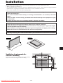 6
6
-
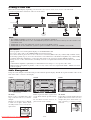 7
7
-
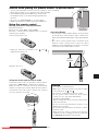 8
8
-
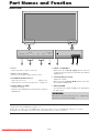 9
9
-
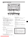 10
10
-
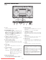 11
11
-
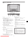 12
12
-
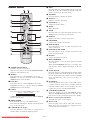 13
13
-
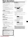 14
14
-
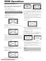 15
15
-
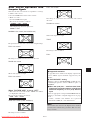 16
16
-
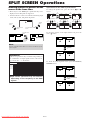 17
17
-
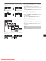 18
18
-
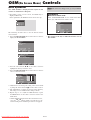 19
19
-
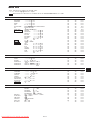 20
20
-
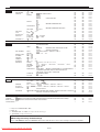 21
21
-
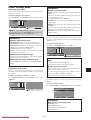 22
22
-
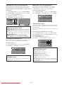 23
23
-
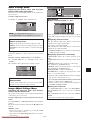 24
24
-
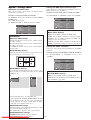 25
25
-
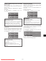 26
26
-
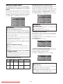 27
27
-
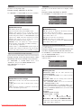 28
28
-
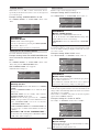 29
29
-
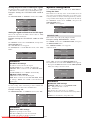 30
30
-
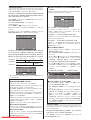 31
31
-
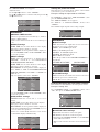 32
32
-
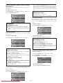 33
33
-
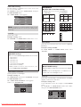 34
34
-
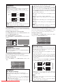 35
35
-
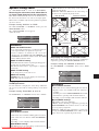 36
36
-
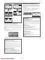 37
37
-
 38
38
-
 39
39
-
 40
40
-
 41
41
-
 42
42
-
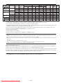 43
43
-
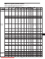 44
44
-
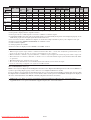 45
45
-
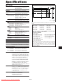 46
46
-
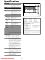 47
47
-
 48
48
-
 49
49
-
 50
50
-
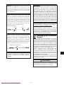 51
51
-
 52
52
-
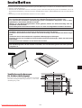 53
53
-
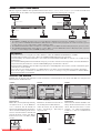 54
54
-
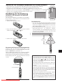 55
55
-
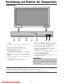 56
56
-
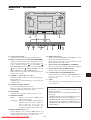 57
57
-
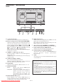 58
58
-
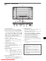 59
59
-
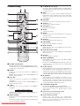 60
60
-
 61
61
-
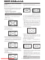 62
62
-
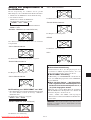 63
63
-
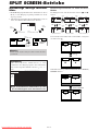 64
64
-
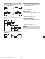 65
65
-
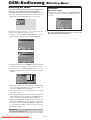 66
66
-
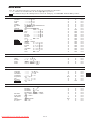 67
67
-
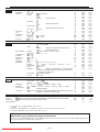 68
68
-
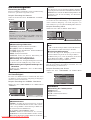 69
69
-
 70
70
-
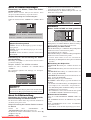 71
71
-
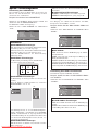 72
72
-
 73
73
-
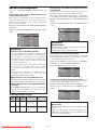 74
74
-
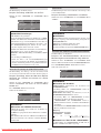 75
75
-
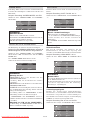 76
76
-
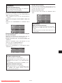 77
77
-
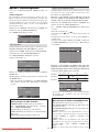 78
78
-
 79
79
-
 80
80
-
 81
81
-
 82
82
-
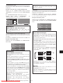 83
83
-
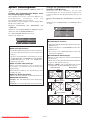 84
84
-
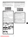 85
85
-
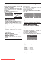 86
86
-
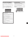 87
87
-
 88
88
-
 89
89
-
 90
90
-
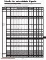 91
91
-
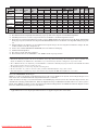 92
92
-
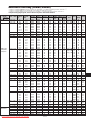 93
93
-
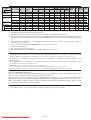 94
94
-
 95
95
-
 96
96
-
 97
97
-
 98
98
-
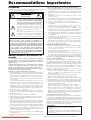 99
99
-
 100
100
-
 101
101
-
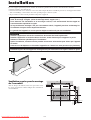 102
102
-
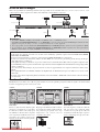 103
103
-
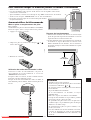 104
104
-
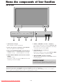 105
105
-
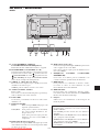 106
106
-
 107
107
-
 108
108
-
 109
109
-
 110
110
-
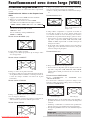 111
111
-
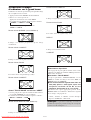 112
112
-
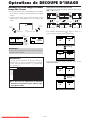 113
113
-
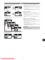 114
114
-
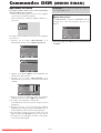 115
115
-
 116
116
-
 117
117
-
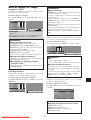 118
118
-
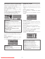 119
119
-
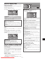 120
120
-
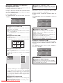 121
121
-
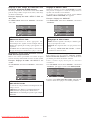 122
122
-
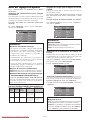 123
123
-
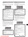 124
124
-
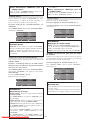 125
125
-
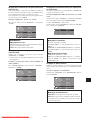 126
126
-
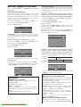 127
127
-
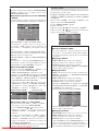 128
128
-
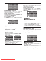 129
129
-
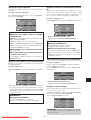 130
130
-
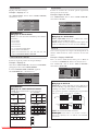 131
131
-
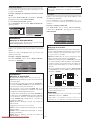 132
132
-
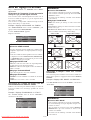 133
133
-
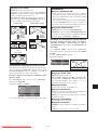 134
134
-
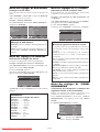 135
135
-
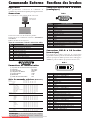 136
136
-
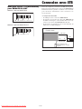 137
137
-
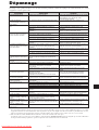 138
138
-
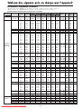 139
139
-
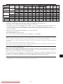 140
140
-
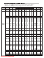 141
141
-
 142
142
-
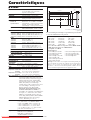 143
143
-
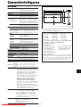 144
144
-
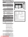 145
145
-
 146
146
-
 147
147
-
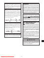 148
148
-
 149
149
-
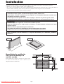 150
150
-
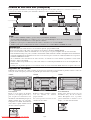 151
151
-
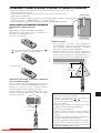 152
152
-
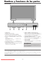 153
153
-
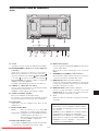 154
154
-
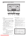 155
155
-
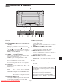 156
156
-
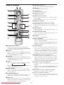 157
157
-
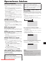 158
158
-
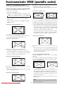 159
159
-
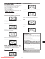 160
160
-
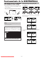 161
161
-
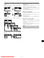 162
162
-
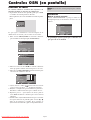 163
163
-
 164
164
-
 165
165
-
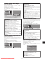 166
166
-
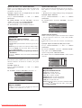 167
167
-
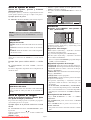 168
168
-
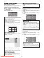 169
169
-
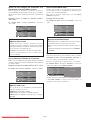 170
170
-
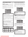 171
171
-
 172
172
-
 173
173
-
 174
174
-
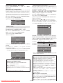 175
175
-
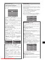 176
176
-
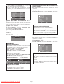 177
177
-
 178
178
-
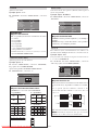 179
179
-
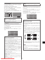 180
180
-
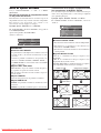 181
181
-
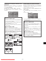 182
182
-
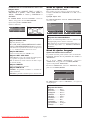 183
183
-
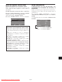 184
184
-
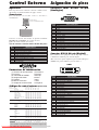 185
185
-
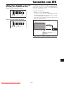 186
186
-
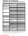 187
187
-
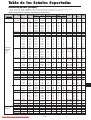 188
188
-
 189
189
-
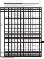 190
190
-
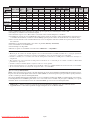 191
191
-
 192
192
-
 193
193
-
 194
194
-
 195
195
-
 196
196
-
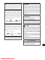 197
197
-
 198
198
-
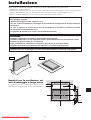 199
199
-
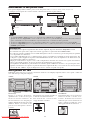 200
200
-
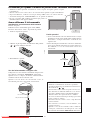 201
201
-
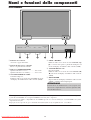 202
202
-
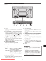 203
203
-
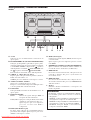 204
204
-
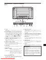 205
205
-
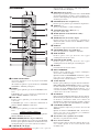 206
206
-
 207
207
-
 208
208
-
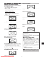 209
209
-
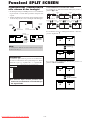 210
210
-
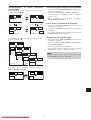 211
211
-
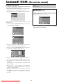 212
212
-
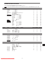 213
213
-
 214
214
-
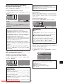 215
215
-
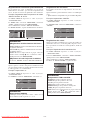 216
216
-
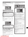 217
217
-
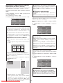 218
218
-
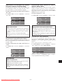 219
219
-
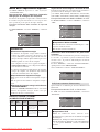 220
220
-
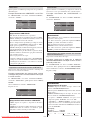 221
221
-
 222
222
-
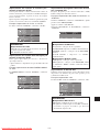 223
223
-
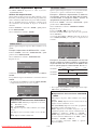 224
224
-
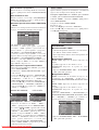 225
225
-
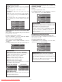 226
226
-
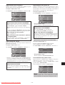 227
227
-
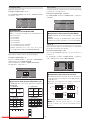 228
228
-
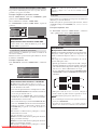 229
229
-
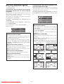 230
230
-
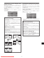 231
231
-
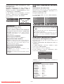 232
232
-
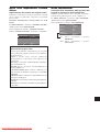 233
233
-
 234
234
-
 235
235
-
 236
236
-
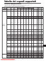 237
237
-
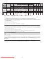 238
238
-
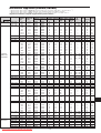 239
239
-
 240
240
-
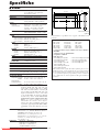 241
241
-
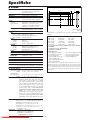 242
242
-
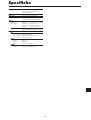 243
243
-
 244
244
-
 245
245
-
 246
246
-
 247
247
-
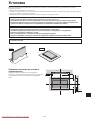 248
248
-
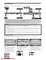 249
249
-
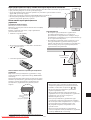 250
250
-
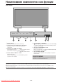 251
251
-
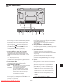 252
252
-
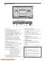 253
253
-
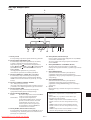 254
254
-
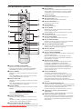 255
255
-
 256
256
-
 257
257
-
 258
258
-
 259
259
-
 260
260
-
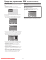 261
261
-
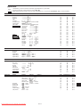 262
262
-
 263
263
-
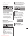 264
264
-
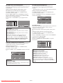 265
265
-
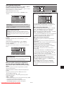 266
266
-
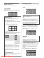 267
267
-
 268
268
-
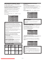 269
269
-
 270
270
-
 271
271
-
 272
272
-
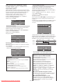 273
273
-
 274
274
-
 275
275
-
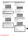 276
276
-
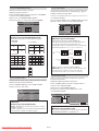 277
277
-
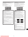 278
278
-
 279
279
-
 280
280
-
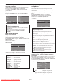 281
281
-
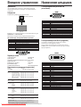 282
282
-
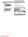 283
283
-
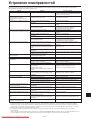 284
284
-
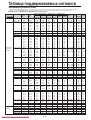 285
285
-
 286
286
-
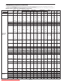 287
287
-
 288
288
-
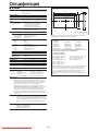 289
289
-
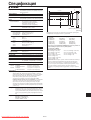 290
290
-
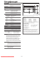 291
291
-
 292
292
-
 293
293
-
 294
294
-
 295
295
-
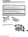 296
296
-
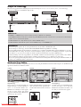 297
297
-
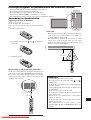 298
298
-
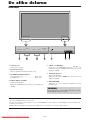 299
299
-
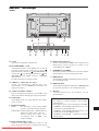 300
300
-
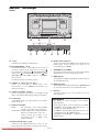 301
301
-
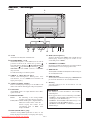 302
302
-
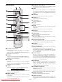 303
303
-
 304
304
-
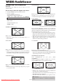 305
305
-
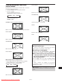 306
306
-
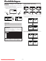 307
307
-
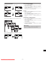 308
308
-
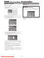 309
309
-
 310
310
-
 311
311
-
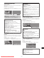 312
312
-
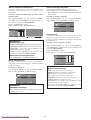 313
313
-
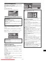 314
314
-
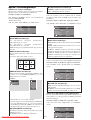 315
315
-
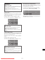 316
316
-
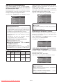 317
317
-
 318
318
-
 319
319
-
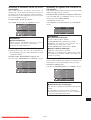 320
320
-
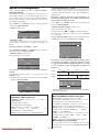 321
321
-
 322
322
-
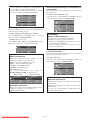 323
323
-
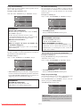 324
324
-
 325
325
-
 326
326
-
 327
327
-
 328
328
-
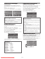 329
329
-
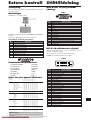 330
330
-
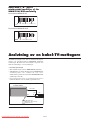 331
331
-
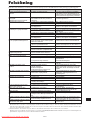 332
332
-
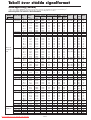 333
333
-
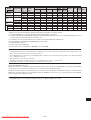 334
334
-
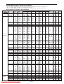 335
335
-
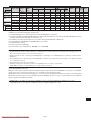 336
336
-
 337
337
-
 338
338
-
 339
339
-
 340
340
-
 341
341
-
 342
342
-
 343
343
-
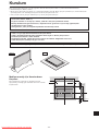 344
344
-
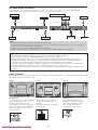 345
345
-
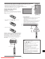 346
346
-
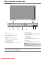 347
347
-
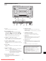 348
348
-
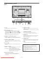 349
349
-
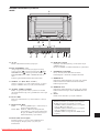 350
350
-
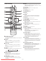 351
351
-
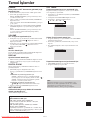 352
352
-
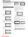 353
353
-
 354
354
-
 355
355
-
 356
356
-
 357
357
-
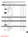 358
358
-
 359
359
-
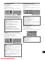 360
360
-
 361
361
-
 362
362
-
 363
363
-
 364
364
-
 365
365
-
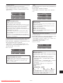 366
366
-
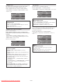 367
367
-
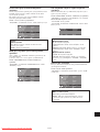 368
368
-
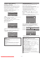 369
369
-
 370
370
-
 371
371
-
 372
372
-
 373
373
-
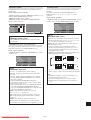 374
374
-
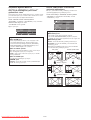 375
375
-
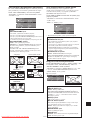 376
376
-
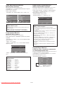 377
377
-
 378
378
-
 379
379
-
 380
380
-
 381
381
-
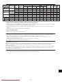 382
382
-
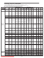 383
383
-
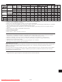 384
384
-
 385
385
-
 386
386
-
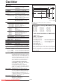 387
387
-
 388
388
-
 389
389
-
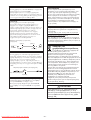 390
390
-
 391
391
-
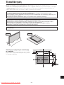 392
392
-
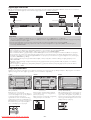 393
393
-
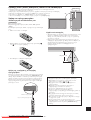 394
394
-
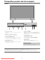 395
395
-
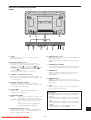 396
396
-
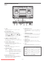 397
397
-
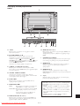 398
398
-
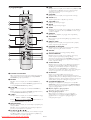 399
399
-
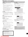 400
400
-
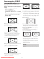 401
401
-
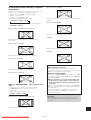 402
402
-
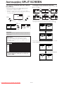 403
403
-
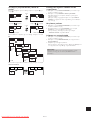 404
404
-
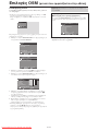 405
405
-
 406
406
-
 407
407
-
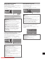 408
408
-
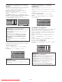 409
409
-
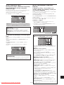 410
410
-
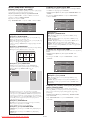 411
411
-
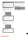 412
412
-
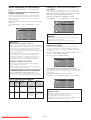 413
413
-
 414
414
-
 415
415
-
 416
416
-
 417
417
-
 418
418
-
 419
419
-
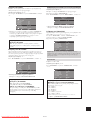 420
420
-
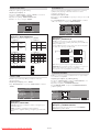 421
421
-
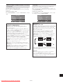 422
422
-
 423
423
-
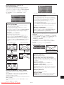 424
424
-
 425
425
-
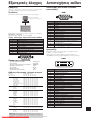 426
426
-
 427
427
-
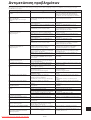 428
428
-
 429
429
-
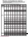 430
430
-
 431
431
-
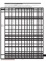 432
432
-
 433
433
-
 434
434
-
 435
435
-
 436
436
-
 437
437


NEC 42XM5 PX-42XM5G Manuel utilisateur
- Catégorie
- Téléviseurs
- Taper
- Manuel utilisateur
dans d''autres langues
- italiano: NEC 42XM5 PX-42XM5G Manuale utente
- Türkçe: NEC 42XM5 PX-42XM5G Kullanım kılavuzu
Documents connexes
-
NEC PlasmaSync® 50XM6 Le manuel du propriétaire
-
NEC plasmasync 60xm5, px-60xm5a Manuel utilisateur
-
-
-
NEC PX-50XM5A Manuel utilisateur
-
-
-
-
-
Autres documents
-
Integra Computer Monitor PLA-50V1 Manuel utilisateur
-
Marantz Flat Panel Television PD4220V Manuel utilisateur
-
-
Panasonic TY42TM4D Mode d'emploi
-
JVC LCT1652-001A Manuel utilisateur
-
-
Dell E2009WFP Mode d'emploi
-
 Keene Electronics APTUS 1 Mode d'emploi
